Week 11- Assembly Workbench
AIM-
In this week’s assignment, you will have to create 2 assemblies according to the content covered in the course videos. You will be provided with 2D diagrams of the components and you will have to first create the individual part files and then create a complete assembly of those part files in the assembly workbench. After creating the assembly make use of the drafting tools to create a 2D drawing similar to the one given in the assignment folder.
INPUT
SOFTWARE USE-CATIA V5
PROCEDURES:
initially we creating a solid models by using given inputs( part dimensions).
Once we get it, and we go to assembly design workbench.
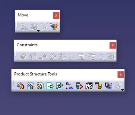
Assembly design tool commands
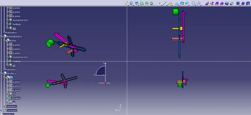
QUICK RETURN MECH.
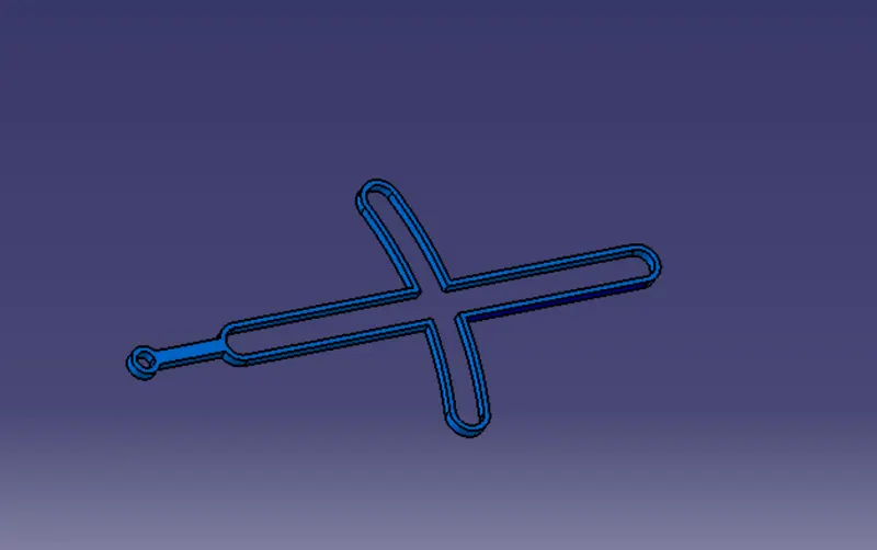
BODY1( FOUR BAR)
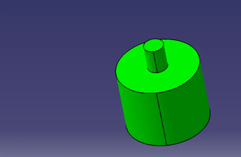
BODY 2(PIN FOR GUIDE)
BODY3(RECTANGULAR ROD)
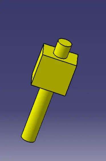
BODY4(KEY)
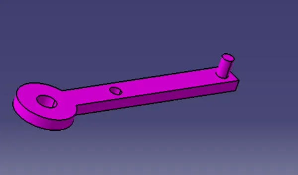
PIN BODY5
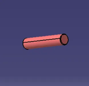
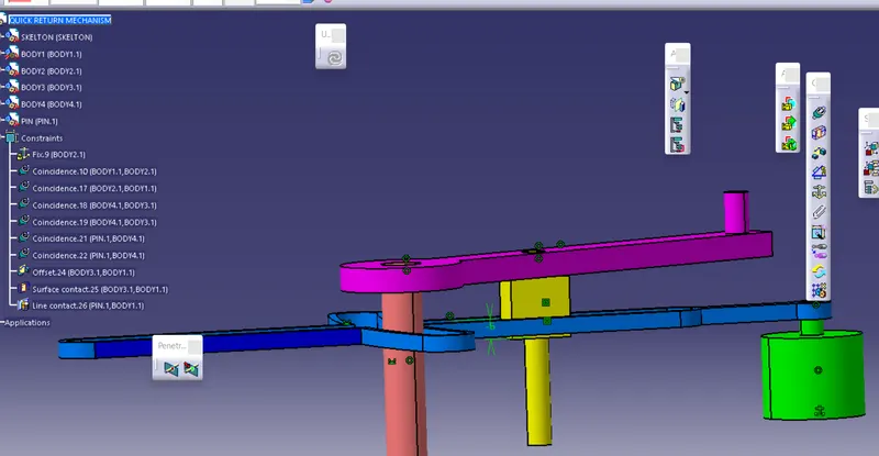
CV JOINT
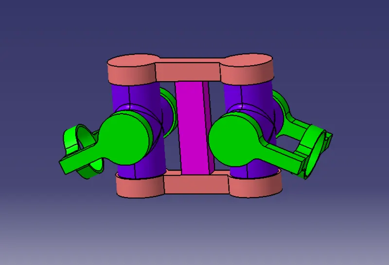
BODY1
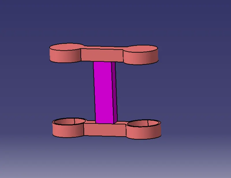
BPDY3
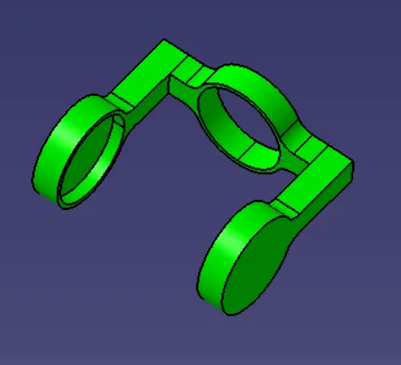
BODY2
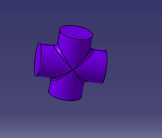
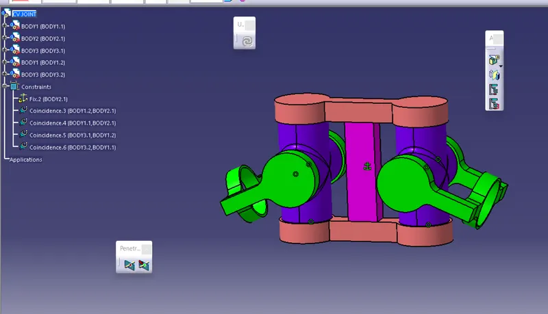
RESULTS:
created 2 assemblies according to the content covered in the course videos. You will be provided with 2D diagrams of the components and you will have to first create the individual part files and then create a complete assembly of those part files in the assembly workbench After creating the assembly make use of the drafting tools to create a 2D drawing similar to the one given in the assignment folder hence it is proved...