Week 10 - Simulating Combustion of Natural Gas.
OBJECTIVE:
To simulate the combustion of methane and air and analyze the species and temperature plots, also understanding the variation in species concentration of pollutants like NOx and device detrimental compounds like soot for better design prospects of combustion systems.
THEORY:
Combustion reactions are there everywhere in our life, from industrial, domestic, consumer applications these reactions are fundamental for everyday systems. They are a set of reactions where a fuel reacting with an oxidizer produces products and heat (exothermic). It is this heat or energy generation which makes these sets of reactions a center of study as the energy liberated can be transformed and utilized for various purposes.
Combustion reactions are mainly of two types, flame mode where there is a thin zone of intense chemical reaction called the "flame", the other being non-flame mode where there is volumetric combustion.
The main purpose of doing a combustion simulation is:
1. We can understand the flow fields and mixing regions
2. We can gauge the species concentration.
3. Temperature fields can be gauged.
4. Concentration of pollutants can be figured out.
5. Computation of diffusion rates and parametric changes of enthalpy and mixture density.
It is a common misconception that combustion reactions are one-step reactions, this notion of combustion can never lead to the precise understanding of chemistry and production of energy through these reactions.
To understand combustion better we need to delve into chemical kinetics, where we study rates of reactions and the path of product and energy formation. Chemical kinetics relates the species concentration and the rates of forwarding and backward reactions, ignition delay, rate of work done, and emission formations.
All combustion reactions have intermediary reactions which govern the time, rate, and path characteristics.
These are coupled differential equations of concentration that can be fed to the computer so that they can be solved. All chemical kinetics solver has a certain algorithm of feeding the data which is the matrix form. The product and reactant matrices are fed to the system and the net reaction rates are calculated. Elementary reactions are of three types biomolecular, unimolecular and thermolecular, biomolecular being the most common one.
The fuel and airflow used for this simulation are going to be turbulent and the mixture material is methane-air-2-step, it contains the following information:
1. List of constituent species
2. All the mixing laws
3. Diffusion coefficients of species.
4. Absorption and scattering coefficients.
Turbulence is a key factor in determining the overall rate of the reaction as it governs mixing. In non-premixed flames, the fuel and oxidizer are mixed through turbulence, converting them into reaction zones, the mixing of hot and cool regions is also better facilitated by turbulence. Since our case is a non-premixed flame, we use the eddy dissipation model where reaction rates are directly proportional to turbulent mixing times defined by kinetic energy and dissipation rates.
The formation of NOx and Soot is because of incomplete combustion, both processes temperature-dependent. The NOx is formed through mechanisms in the premixed and diffusion burning. There are various pathways that govern the NOx formation namely Thermal, Prompt Fuel, and Intermediate. Thermal NOx depends on the temperature and chemical reactions.
Soot production is a side effect of the combustion process, where carbon nanoparticles are formed due to high temperature and fuel-rich mixtures. The prediction of soot characteristics becomes difficult because of complex gas chemistry, numerous mechanisms, and radiative heat transfers.
Mechanisms like inception, coagulation, surface growth, and oxidation all affect the final concentration. Soot formation in methane begins with acetylene, which grows into polyaromatic hydrocarbons which grow into soot. Other fuels like kerosene have certain aromatics which accelerate the growth of soot.
Many models are implemented for soot modeling, but the Moss-Brooke-Hall model shows the most promising formation process.
SETUP:
We first begin with the geometry setup and clean up from the file.
It is a 3D geometry having three elements, which cannot be simulated in whole hence a 2D section is taken assuming axisymmetric flow. The clean-up can be done by using the split plane option as shown.
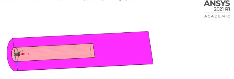
The quarter cut
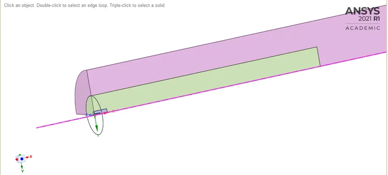
The final 2D section is to be used. The small slit is the separator between the fuel and air inlets.
We can measure the dimensions after splitting the model, then using those dimensions we can create a new 2D design.

MESH:
The meshing for the problem is relatively simple
1. Element size- 2mm
2. Capture proximity- Yes, (3 elements)
Set smoothing to high and generate mesh, the element type is quadrilateral
The mesh around the inlet spacing
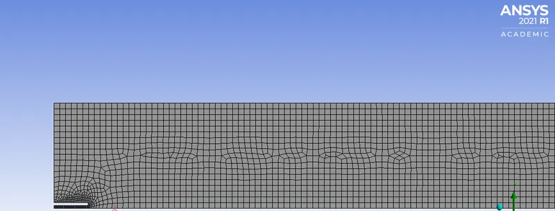 .
.
Elements-4517, Nodes-14117
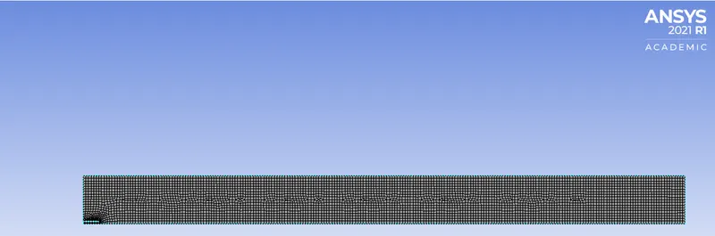
The named selections have to be done carefully:
1. The fuel inlet is the smallest edge below the slit.
2. The larger edge above the slit is the air inlet.
3. The bottom edge of the 2D geometry is the axis, and the top edge is the wall.
4. The last edge is named the outlet.
FLUENT SETUP:
The fluent setup is done in the following way:
1. Pressure-based steady-state flow, axisymmetric with absolute velocity formulation. Gravity enabled in the negative Y direction 9.8m/s^2.
2. Turbulence model is k-epsilon with standard wall functions.
3. Turn the energy equation on.
4. Select the species tab to enable the species transport>volumetric reaction>inlet & diffusion energy source>methane-air-2 step>eddy dissipation.
5. For individual species in the NOx model enable thermal NOx pathway, and for Soot enable one-step method.
6. In the boundary conditions for air inlet the velocity is set for 0.5m/s, with O2 mass fraction as 0.23, with N2 as 0.77
7. For fuel inlet the velocity is 80m/s with CH4 mass fraction and water mass fraction specified as follows:
a. Part-1 (CH4-1, H20-0) This is where no water is added also specified as PART-1
b. For 5% water (CH4-0.95, H20-0.05) In our reference CASE-1
c. For 15% water (CH4-0.85, H20-0.15) In our reference CASE-2
d. For 20% water (CH4-0.80, H20-0.20) In our reference CASE-3
e. For 30% water (CH4-0.70, H20-0.30) In our reference CASE-4
8. Hybrid initialization for every different case setup.
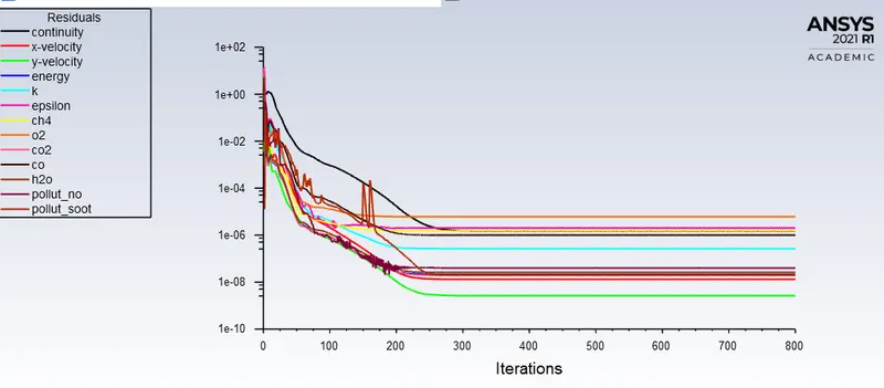
9. Uncheck all convergence criteria in monitor settings.
10. Run for 800-1000 iterations.
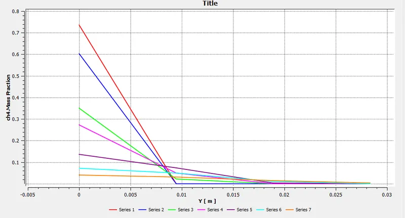
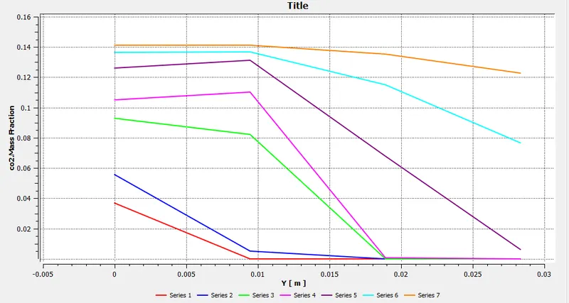
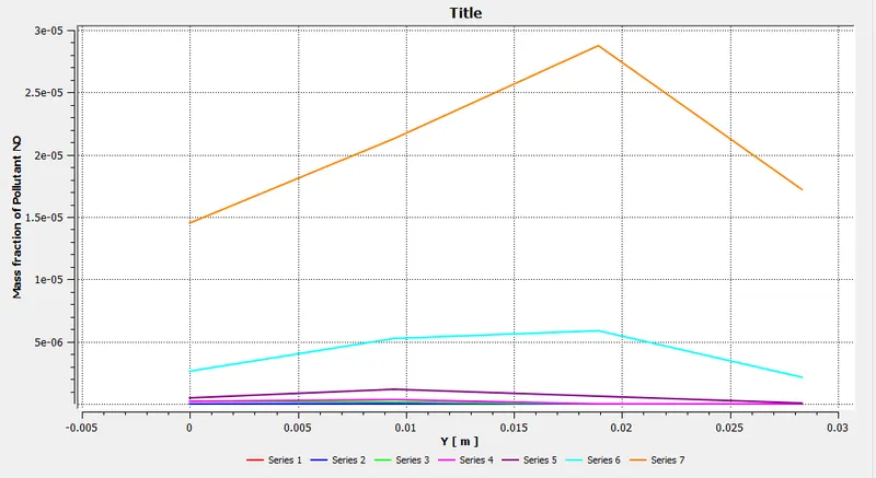
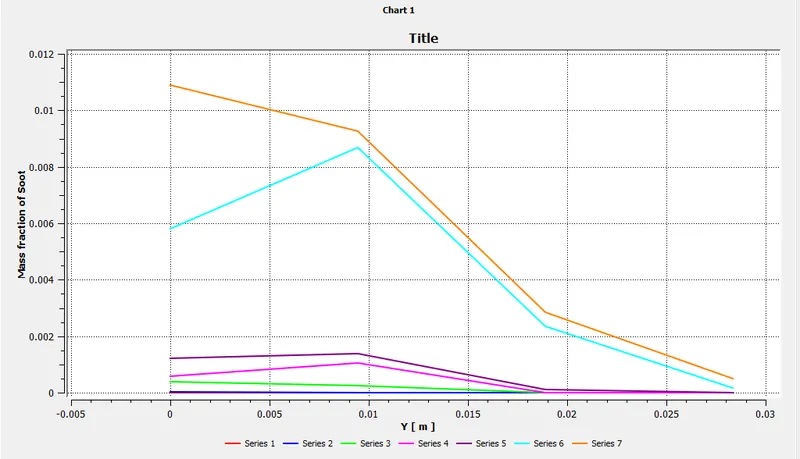
11. For the species concentration we duplicate lines, specify the series and graph settings in the chart option of ANSYS post-processing.
RESULTS AND OBSERVATIONS:
For Part-1
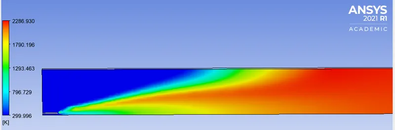
Temperature contour
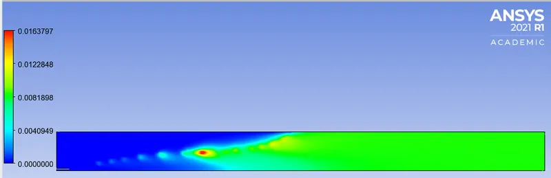
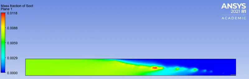
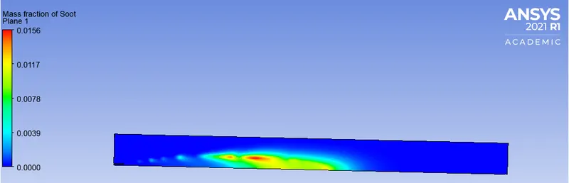
Soot contours
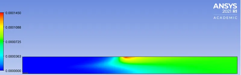
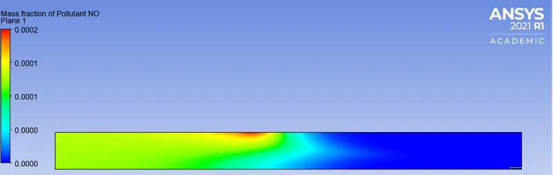
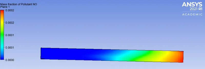
NO contours
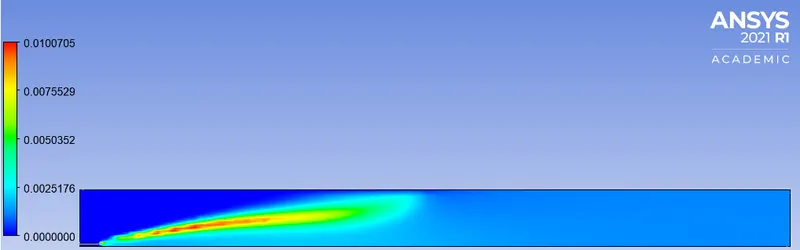
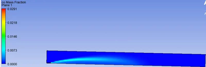
CO contour
CO2 contour
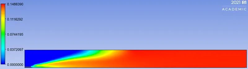
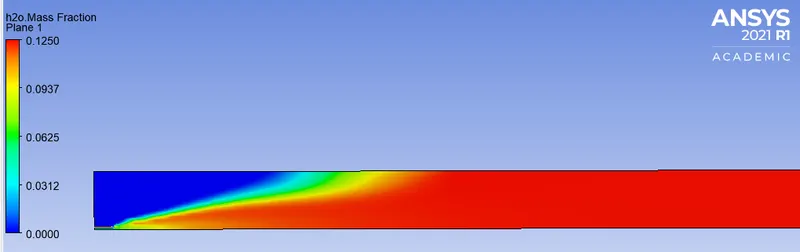
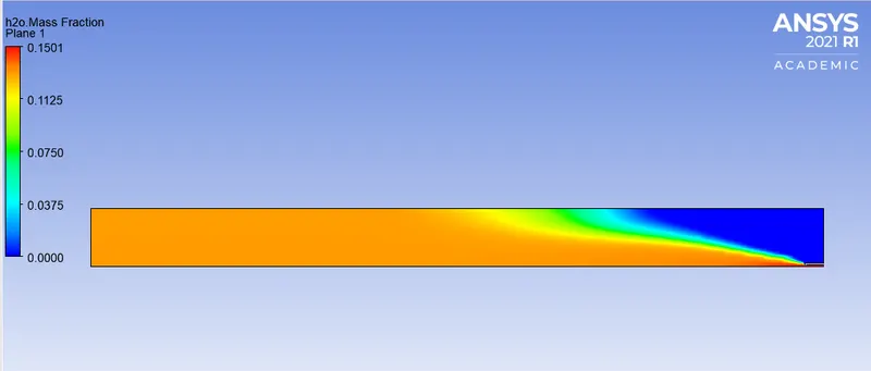
H20 contour
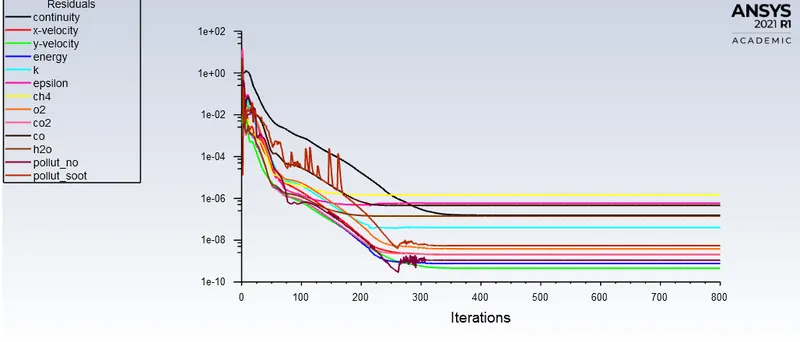
Residuals
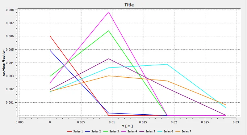
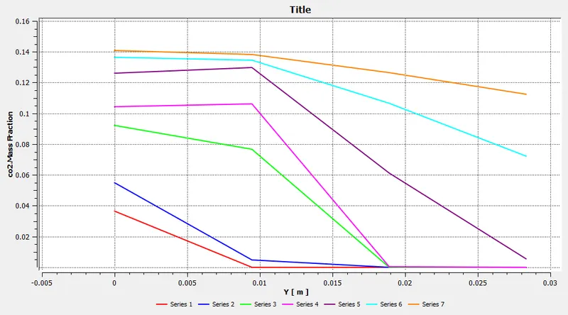
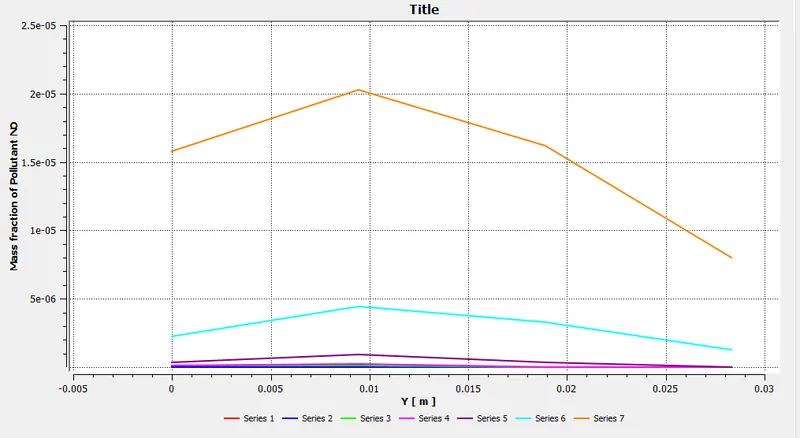
Species concentration plots w.r.t Y-axis
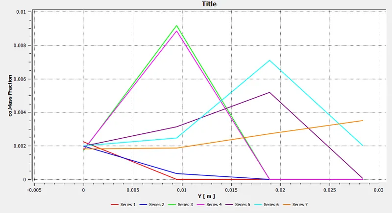
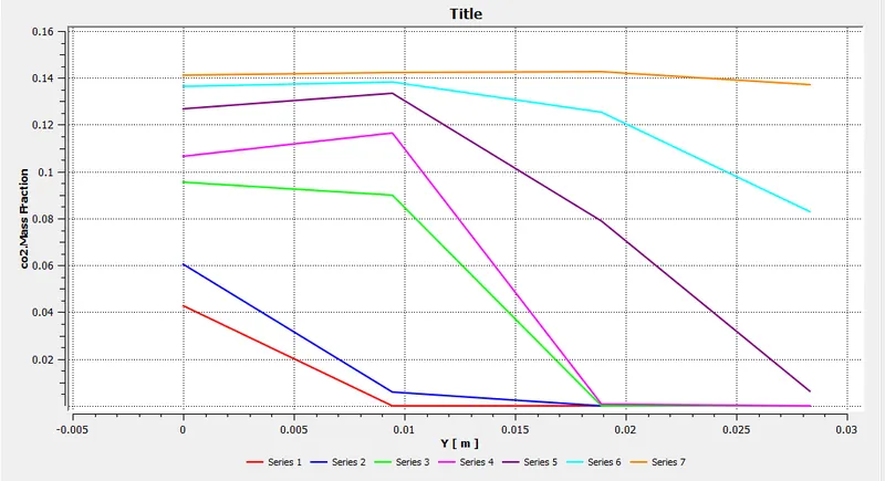
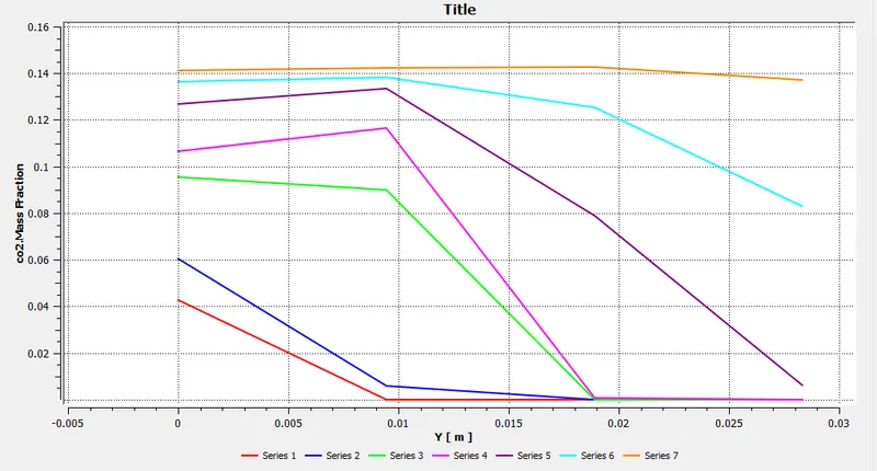
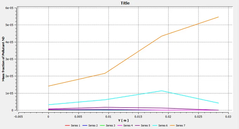
CASE-1
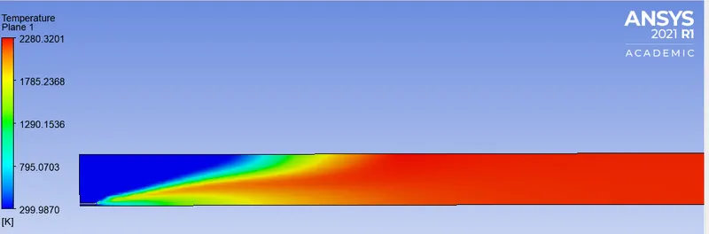
Temperature contour
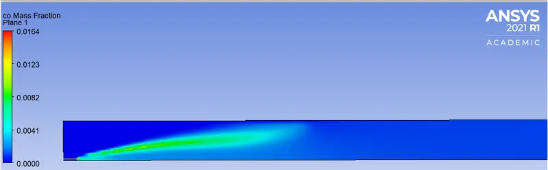
CO contour
CO2 contour

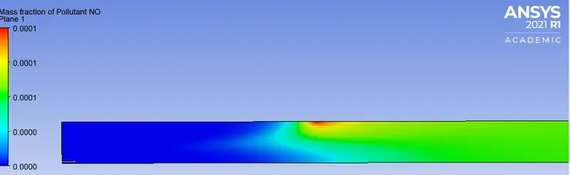
NO contour
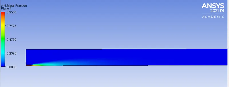
CH4 contour
Soot contour
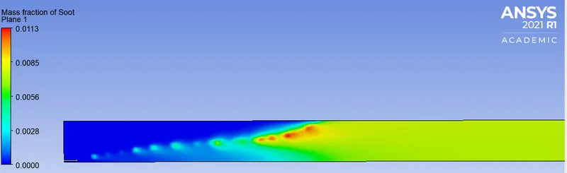
PLOTS FOR CASE 1
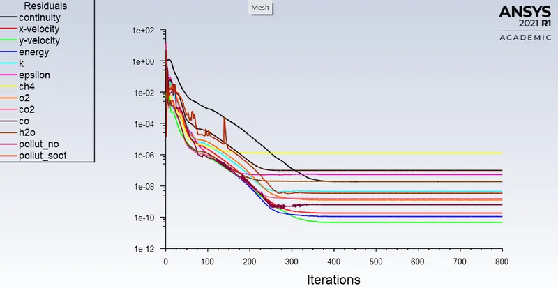
Residuals:
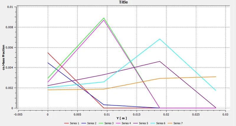
CO mass fraction
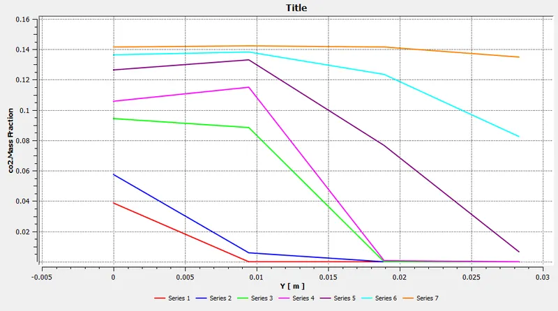
CO2 mass fraction
CASE-2
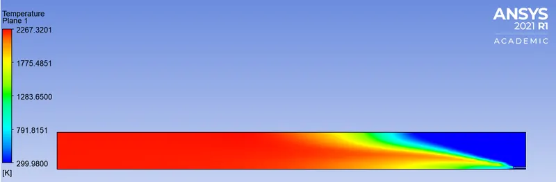
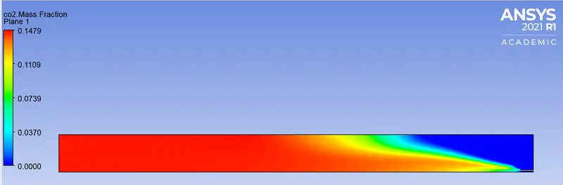
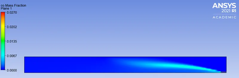
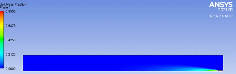
PLOTS FOR CASE-2
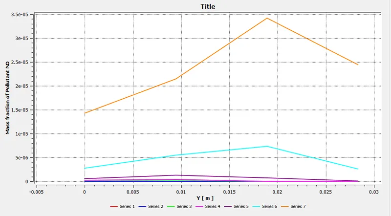
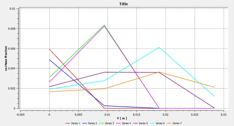
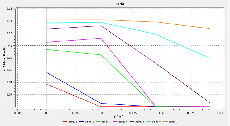
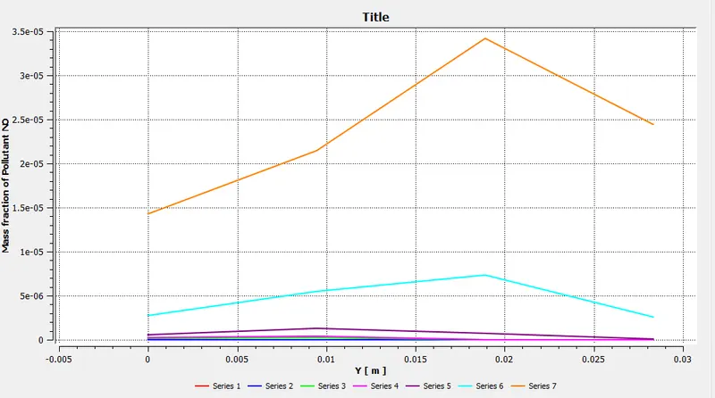
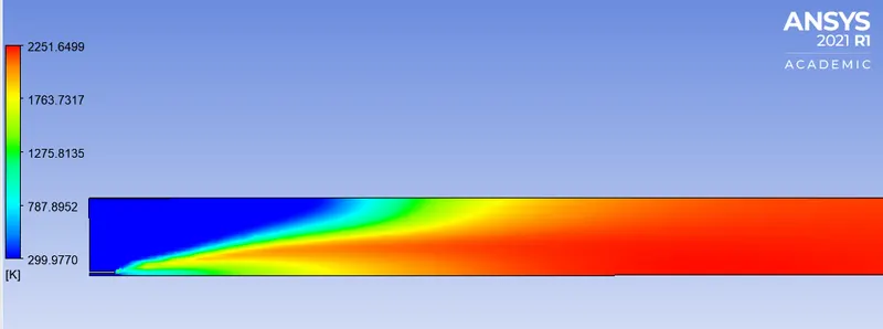
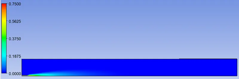
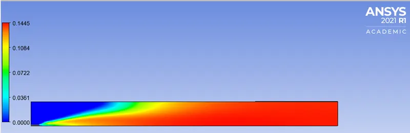
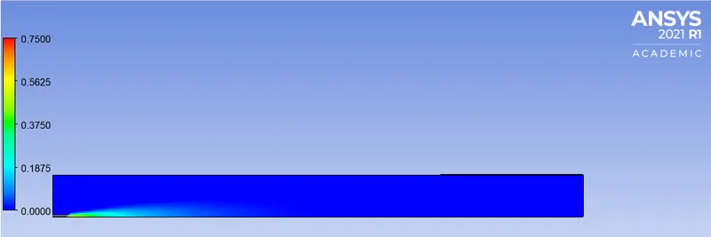
CASE-3 CONTOURS
Temperature
CO mass fraction
CO2 mass fraction
CH4 mass fraction
NO mass fraction
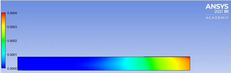
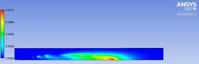
Soot mass fraction
PLOTS
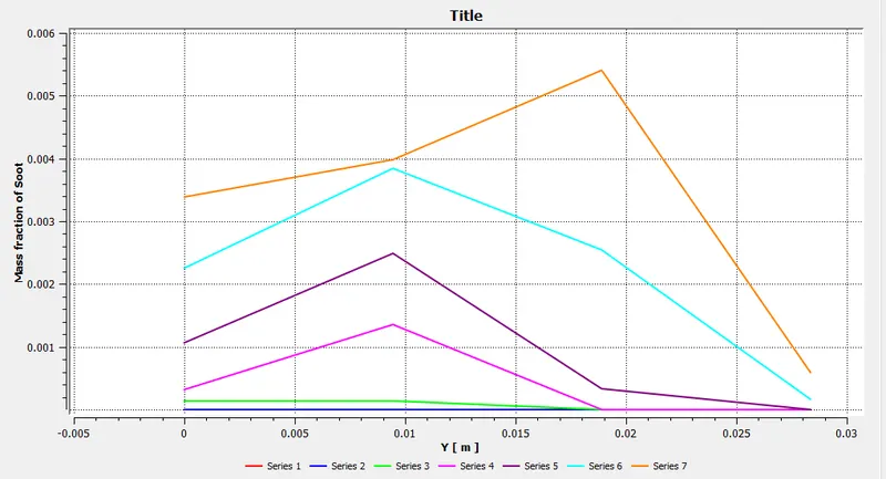
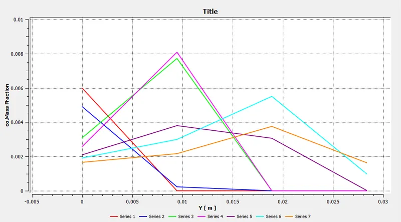
CASE-4
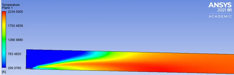
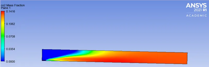
PLOTS
OBSERVATION:
Here the pollutants like NOx and Soot are mainly mentioned in the table, other reactants like N2 and H20 are not mentioned as we are more interested in studying the effect of water on emission concentration.
| CASE'S/MASS FRACTION | C0 | CO2 | NO | SOOT |
| PART-1 | 0.0100705 | 0.1488 | 0.00016568 | 0.0163797 |
| CASE-1 (5%) | 0.0163739 | 0.1485 | 0.00014332 | 0.0112758 |
| CASE-2 (15%) | 0.0269882 | 0.1478 | 0.000135688 | 0.0117841 |
| CASE-3 (20%) | 0.0273422 | 0.14448 | 0.000122409 | 0.0111874 |
| CASE-4 (30%) | 0.02912 | 0.141584 | 0.000116008 | 0.0106085 |
CONCLUSION:
1. The maximum amount of CO2, NO, and Soot emissions are when there is CH4 of mass fraction 1, i.e no water, the maximum average temperature is 2300K.
2. By adding water to the fuel inlet we can reduce the NOx emissions the least are seen in 30% water.
3. The mass fraction of CO2 also decreases with an increase in water content, least seen in 30% water. The concentration of N2 remains constant, meaning the flame instability of the burner is almost constant, for all cases of combustion.
4. Soot mass fraction initially decreases, but between CASE-2 & 3 there is a slight spike in Soot but in 30% water it significantly reduces.
5. We can reduce the emission concentration of pollutants by adding water.