Week 10 - Simulating Combustion of Natural Gas.
Aim: -
Part I
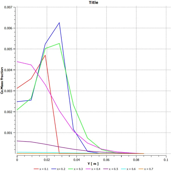
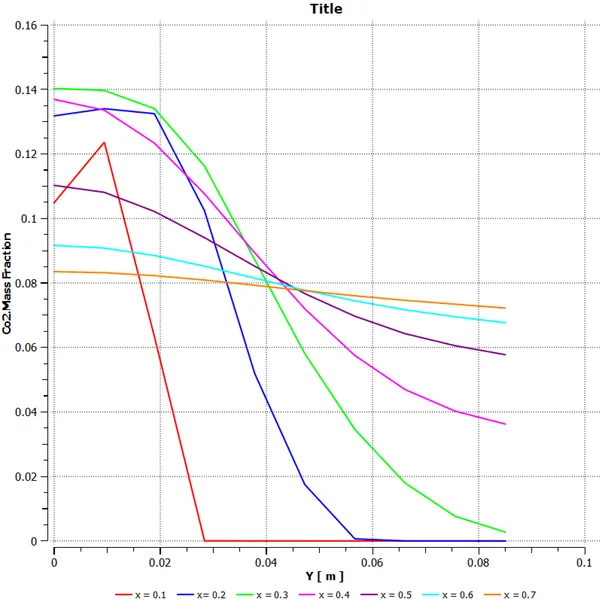
Perform a combustion simulation on the combustor model and plot the variation of the mass fraction of the different species’ in the simulation using line probes at different locations of the combustor. You need to plot for CO2, H2O, CH4, N2, O2, NOx emissions & Soot formation.
Part II
Add the water content in the fuel from 5% to 30% by mole and observe the effect of it on the results. It is necessary to provide line plots and contours.
INTRODUCTION TO COMBUSTION
Combustion is a high-temperature exothermic redox chemical reaction between a fuel (the reductant) and an oxidant, usually atmospheric oxygen, that produces oxidized, often gaseous products, in a mixture termed as smoke. Combustion is often a complicated sequence of elementary radical reactions. Solid fuels, such as wood and coal, first undergo endothermic pyrolysis to produce gaseous fuels whose combustion then supplies the heat required to produce more of them. A simple example can be seen in the combustion of hydrogen and oxygen into water vapor, a reaction commonly used to fuel rocket engines. This reaction releases 242 kJ/mol of heat and reduces the enthalpy accordingly. Comprehensive combustion modeling and simulation is an essential and integral part of modem design/optimization of low-emissions, high-performance combustors.
Various combustion simulations that can be performed are: -
Based on mixing
1) Premixed combustion – in premixed combustion the fuel and the oxidizer are mixed at molecular level prior to the occurrence of any significant chemical reaction. Combustion occurs as a flame front propagating into the unburnt reactants. Examples of premixed combustion include aspirated internal combustion engines, lean premixed gas turbine combustors, and gas-leak explosions. Premixed combustion is much more difficult to model than non-premixed combustion.
2) Non premixed combustion - In non-premixed combustion, fuel and oxidizer enter the reaction zone in distinct streams. This is in contrast to premixed systems, in which reactants are mixed at the molecular level before burning. Examples of non-premixed combustion include pulverized coal furnaces, diesel internal-combustion engines and pool fires. Under certain assumptions, the thermochemistry can be reduced to a single parameter:the mixture fractions
3) partially premixed combustion – it is a modern combustion process intended to be used in internal combustion engines. In this method engine injects and premixes a charge during compression stroke. Thus, premixed charge is too lean to ignite during the compression stroke, the charge ignites after the last fuel injection near the TDC. Its high specific power, high fuel efficiency and low exhaust pollution makes it a promising technology.
GEOMETRY
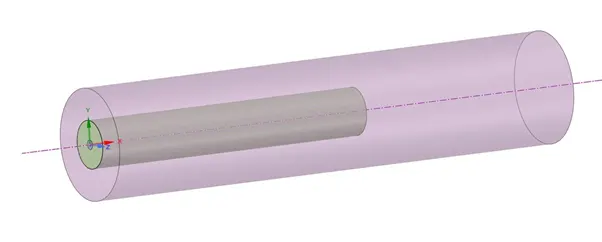
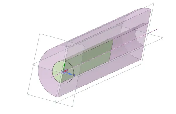
A Simple 3d combustor model has been designed using CAD software. We need not use the full model for analysis as 2D simulation gives pretty accurate results. Split body tool has been used to split the model in half.
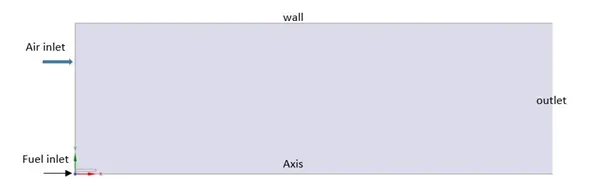
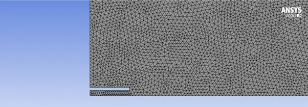
2d computational domain is shown below.
MESHING
Triangle method has been used to mesh the computational domain. As the geometry is pretty simple tri-mesh serves the purpose. The details of mesh has been provided below.
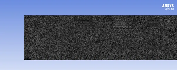
Mesh size = 1mm
Capture proximity – on
No. of gap cells = 3
CASE SETUP
The simulation has been performed using pressure-based solver. Part 1 shows the combustion simulation has been performed correctly and part 2 shows the effect of water in the formation of pollutant No and soot. The pictures below shows the steps to setup the case in fluent.
1) axisymmetric flow has been turned on, as it helps in modelling only a portion of the domain and results can be calculated for the whole body.
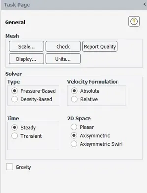
2) solver used – pressure based
Time – steady state
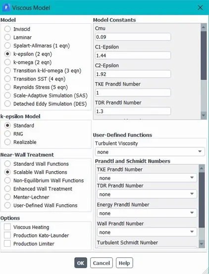
3) energy option in turned on for the calculation of flame temperature.
Viscous model – K – epsilon turbulence model
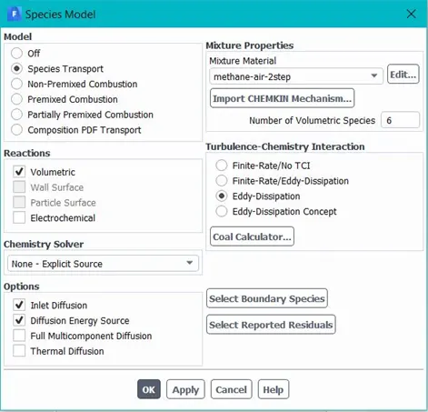
4) species model – species transport
Reactions – volumetric
Inlet diffusion and diffusion energy source options are turned on
Mixture material – methane-air is used for simulation of part 1
Methane-air 2 step is used for part as it allows to add water in fuel.
Turbulence-chemistry interaction – eddy dissipation
In Eddy-dissipation model Reaction rates are assumed to be controlled by the turbulence, so expensive Arrhenius chemical kinetic calculations can be avoided. The model is computationally cheap, but, for realistic results, only one or two step heat-release mechanisms should be used.
BOUNDARY CONDITIONS
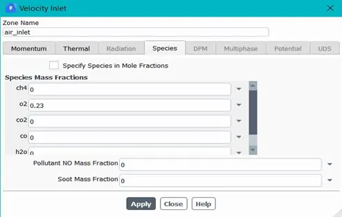
AIR INLET: - velocity = 0.5 m/s
Mass fraction of O2 = 0.23
FUEL INLET: -
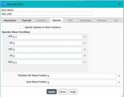
Velocity = 80 m/s
Mass fraction of Ch4 = 1
Mass fraction of Ch4 and H2O has been varied to study the effect of water in production of pollutant No and soot.
RESULT AND DISCUSSIONS
PART 1
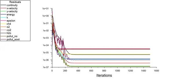
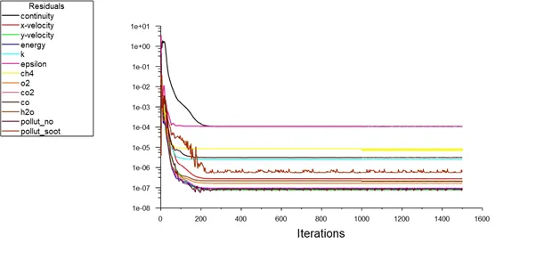
Residuals plot
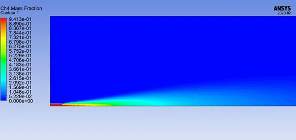
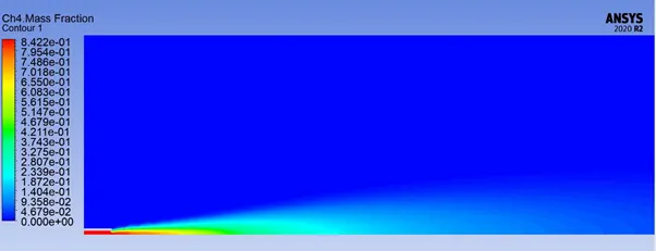
Mass fraction contour of CH4
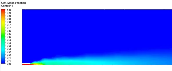
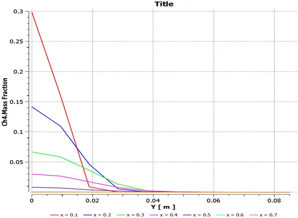
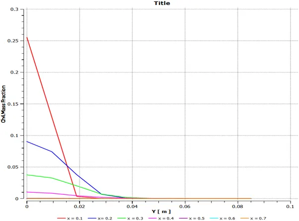
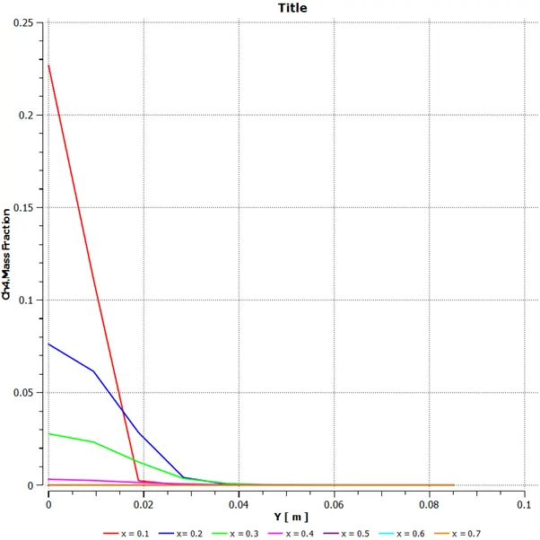
Chart showing variation of CH4 along the y axis at different locations in longitudinal direction
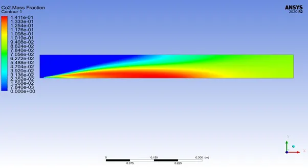
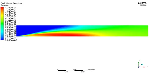
Mass fraction contour of Co2
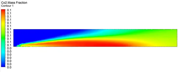
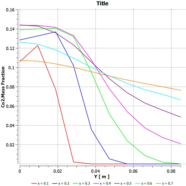
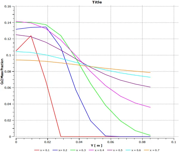
Chart showing variation of Co2 along the y axis at different locations in longitudinal direction
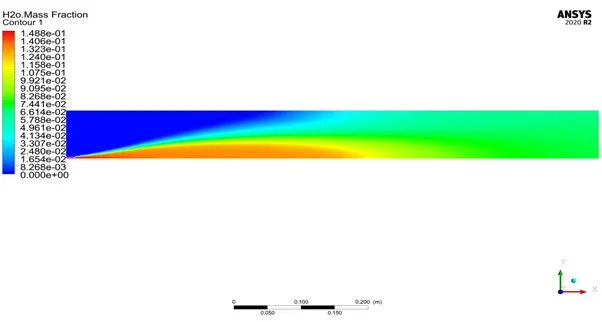
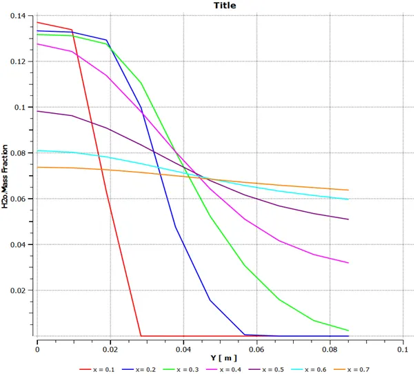
Mass fraction contour of H2o
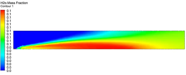
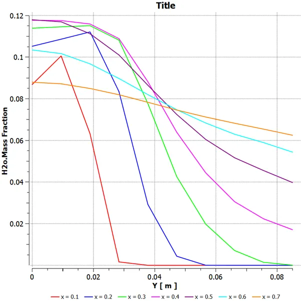
Chart showing variation of H2o along the y axis at different locations in longitudinal direction
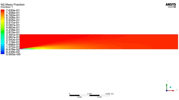
Mass fraction contour of N2
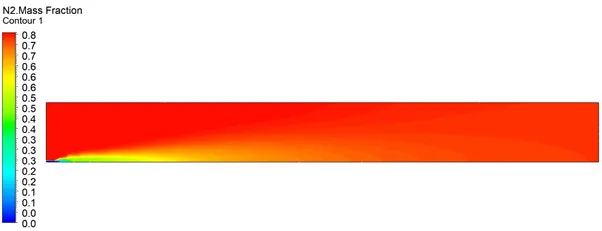
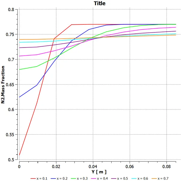
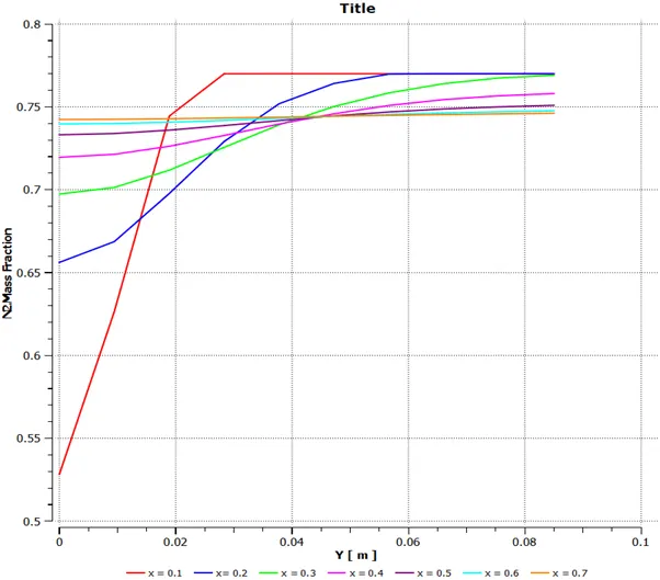
Chart showing variation of N2 along the y axis at different locations in longitudinal direction
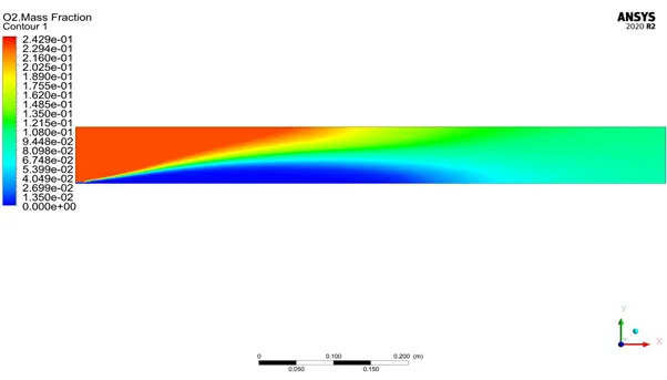
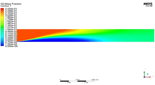
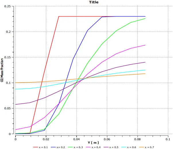
Mass fraction contour of O2
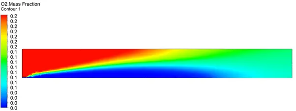
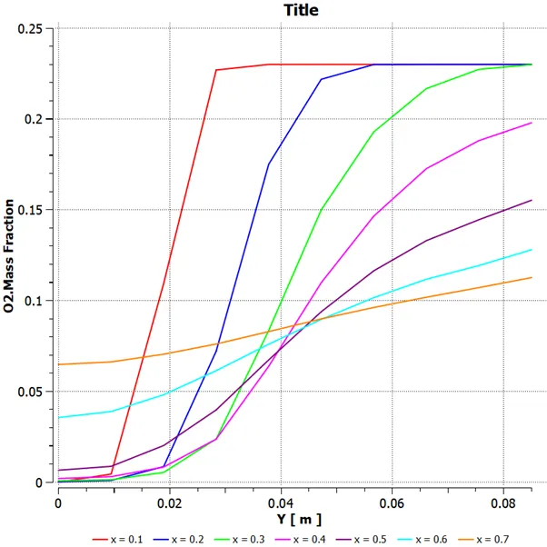
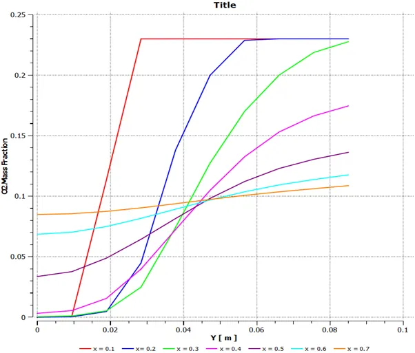
Chart showing variation of O2 along the y axis at different locations in longitudinal direction
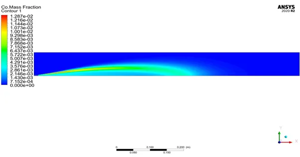
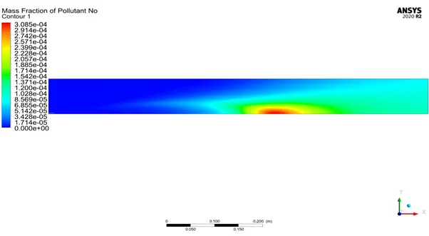
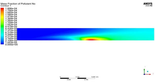
Mass fraction contour of pollutant No
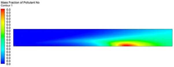
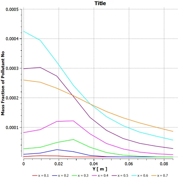
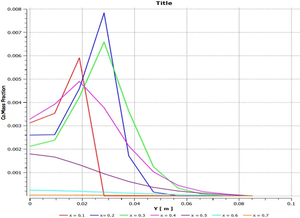
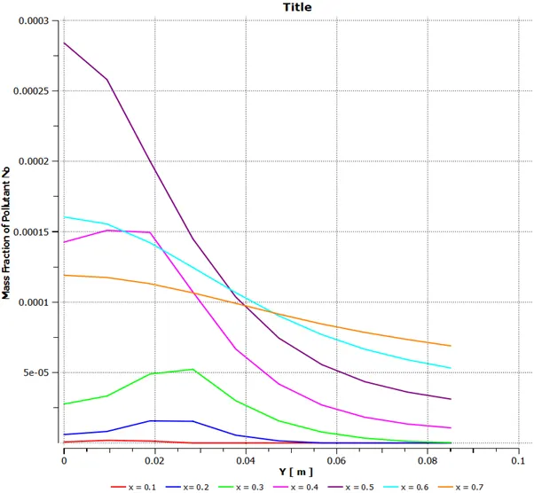
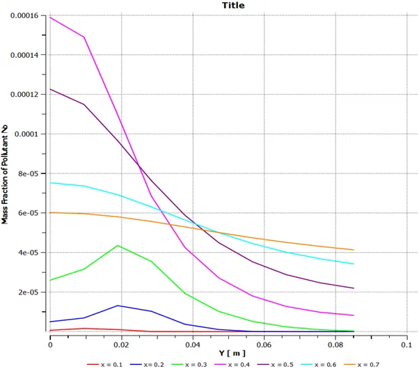
Chart showing variation of Pollutant No along the y axis at different locations in longitudinal direction
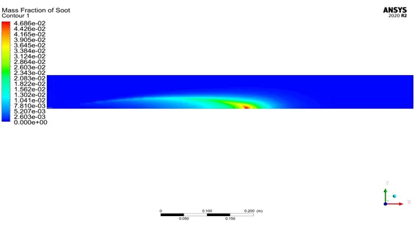
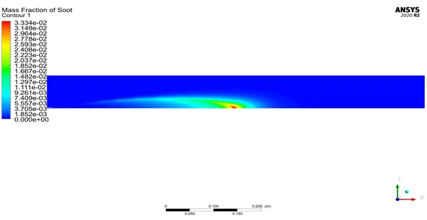
Mass fraction contour of soot
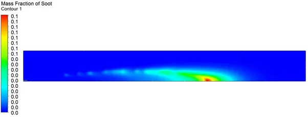
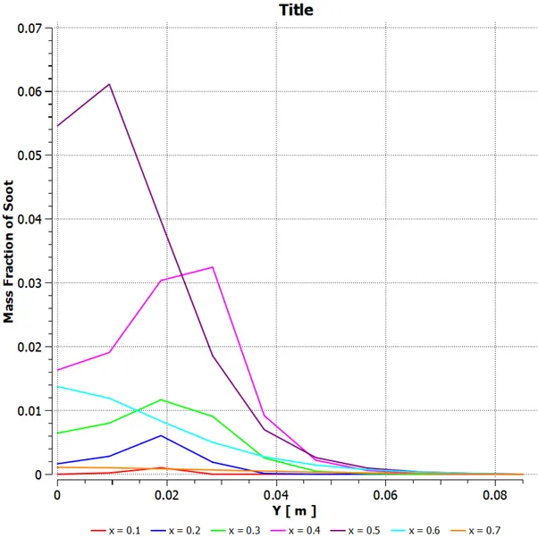
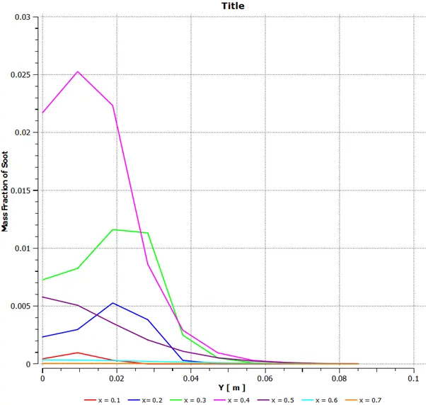
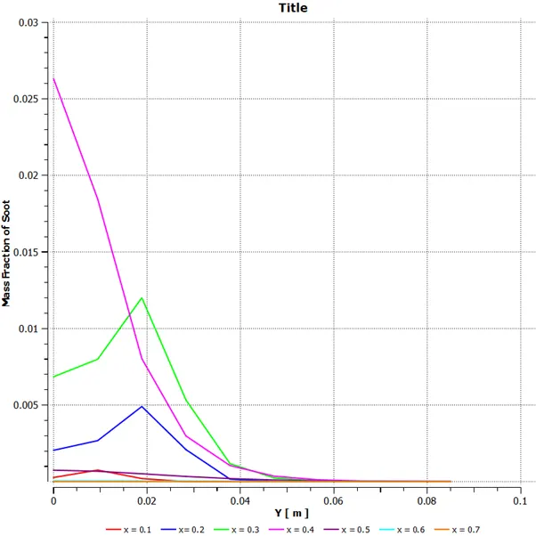
Chart showing variation of Soot along the y axis at different locations in longitudinal direction
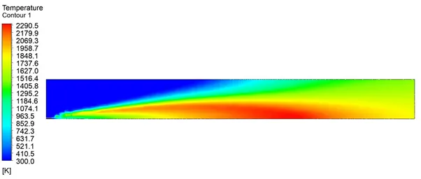
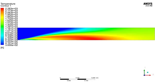
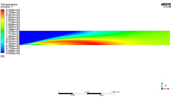
Temperature contour
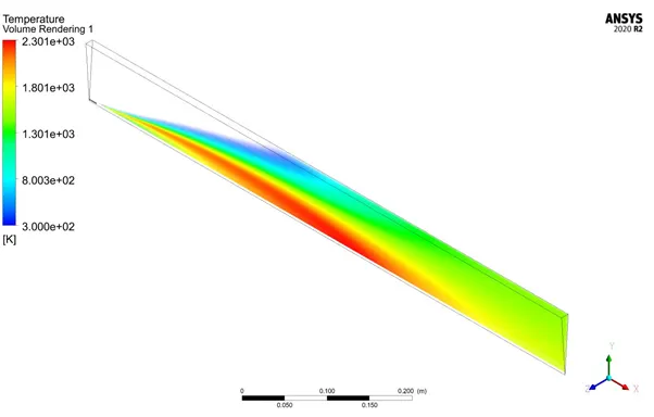
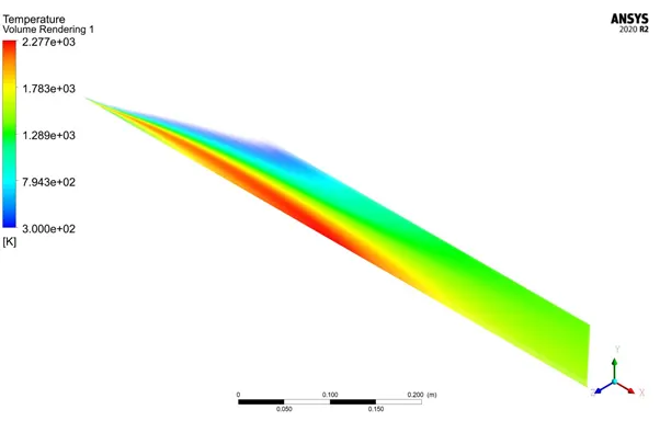
Temperature volume rendering

PART 2
CASE 1: -
Ch4 = 0.95, H2O = 0.05
Residual plot
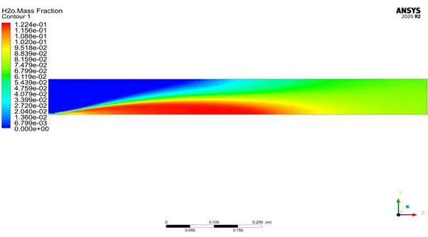
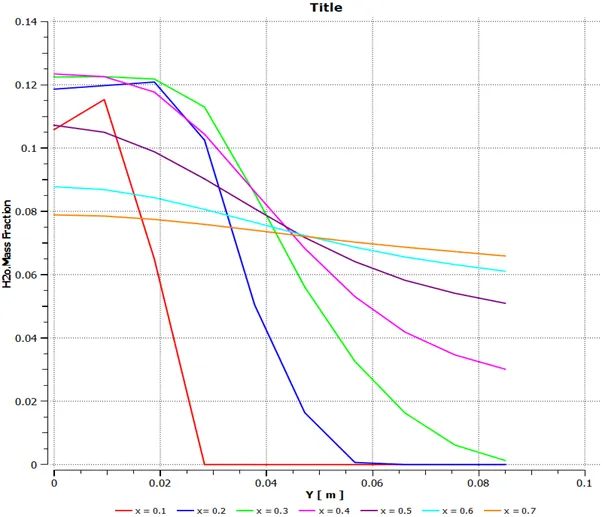
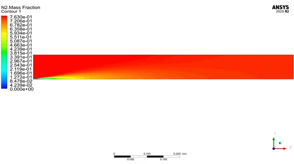
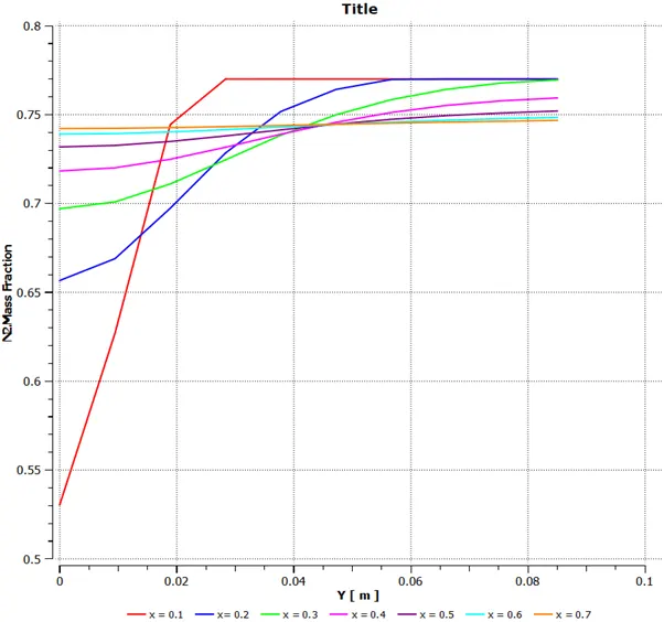
CASE 3: -
Ch4 = 0.85, H2O = 0.15
Residual plot
CASE 4: -
Ch4 = 0.7, H2O = 0.3
Residuals plot
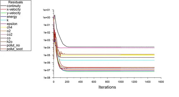
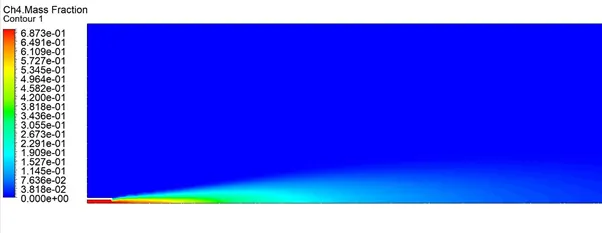
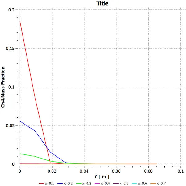
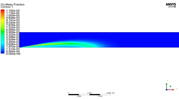
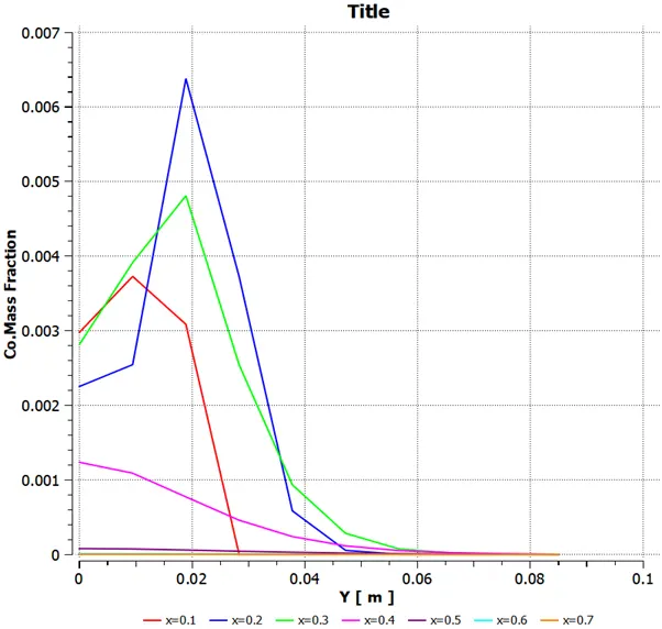
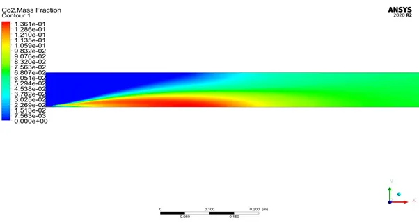
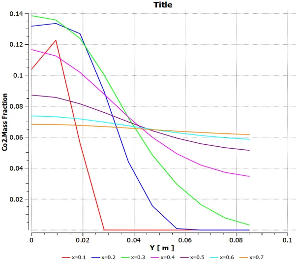
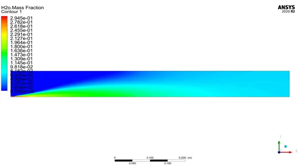
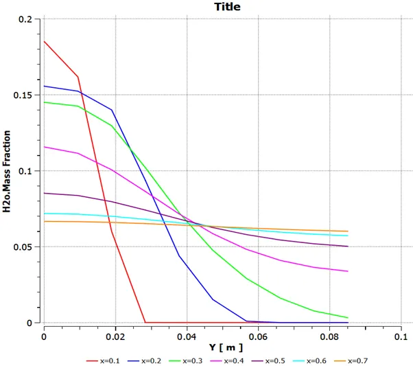
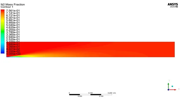
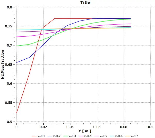
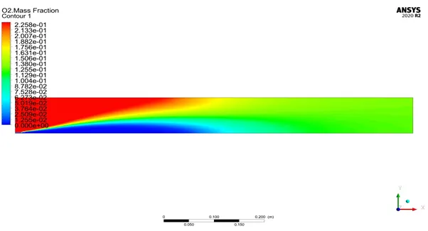
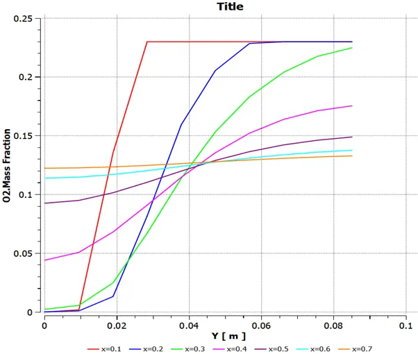
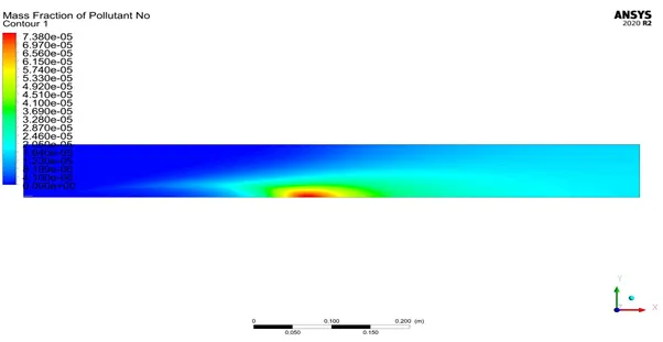
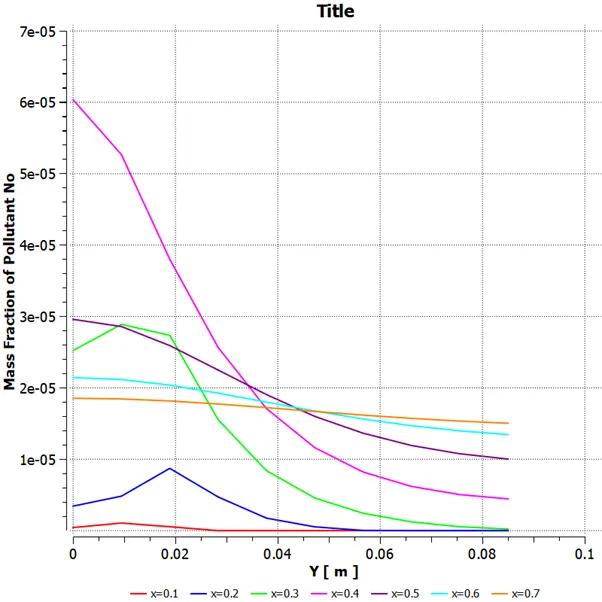
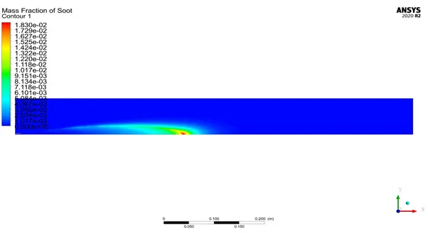
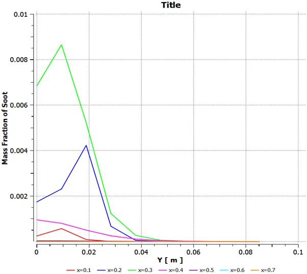
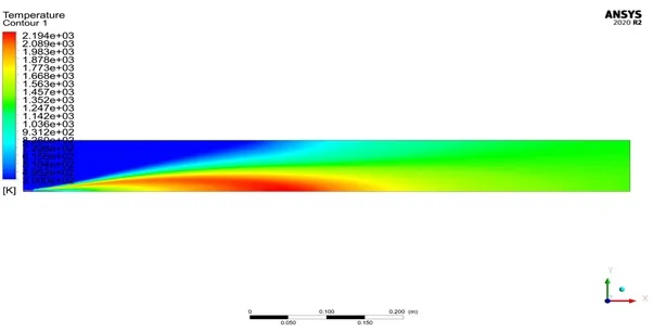
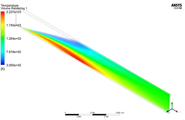
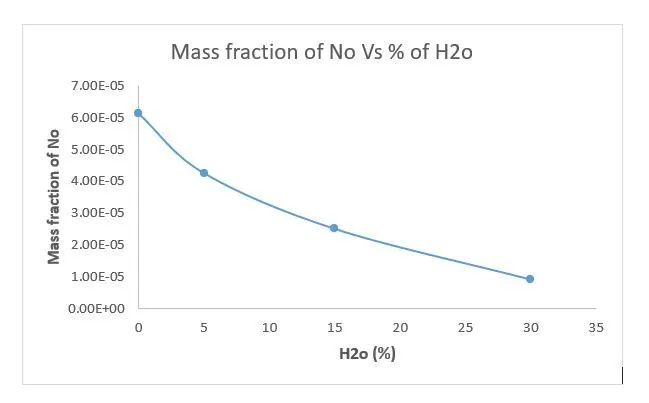
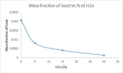
Table below shows the variation of mass fraction of pollutant NO and soot with increasing percentage of water in fuel.
|
cases |
% of H2o |
Mass fraction of No |
Mass fraction of soot |
|
1 |
0 |
6.140687e-05 |
0.00208055 |
|
2 |
5 |
4.264642e-05 |
0.00081245944 |
|
3 |
15 |
2.512226e-05 |
0.0004147995 |
|
4 |
30 |
9.174815e-06 |
0.0001339875 |
CONCLUSIONS
- With the increment in amount of water in fuel, the mass fraction of pollutant No and soot both decreases. It has been widely reported in literature that reduction in No is because of thermal effect. The mechanism behind the reduction of soot are not well understood. The water could reduce soot formation via physical, chemical or thermal effect.
- Supplying water into the combustion chambers of diesel engines is a widely used method to reduce the harmful gases from exhaust. Various systems which are being studied for making fuel water mixture are: - continuous water injection into the scavenging air, humid air motor, direct water injection, fuel water emulsion supply system using emulsifiers etc.
- From the present simulation it has also been observed that flame temperature decreases significantly with increase in water percentage. The lower flame temperatures consequent to water addition decrease the rate of fuel pyrolysis and carbon formation. The accompanying lower NO x emissions can also be attributed to decreased flame temperatures as the reaction mechanism responsible for their formation (Zeldovich mechanism) is highly temperature sensitive.
REFERENCES
- Leszek Chybowski Rafał Laskowski “An overview of systems supplying water into the combustion chamber of diesel engines to decrease the amount of nitrogen oxides in exhaust gas” Journal of Marine Science and Technology (2015) 20, 393–405
- V, K. RAO and M. F. BARDON “The Effect of Water on Gas Phase Soot Formation in Laminar Diffusion Flames” COMBUSTION AND FLAME 55: 73-78 (1984)
- Charles E. Roberts, David Naegeli and Christopher Chadwell “The Effect of Water on Soot Formation Chemistry” 2005-01-3850