Week 10 - Simulating Combustion of Natural Gas.
AIM:-
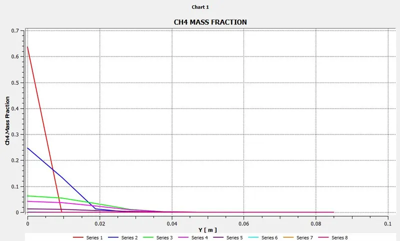
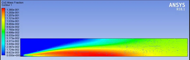
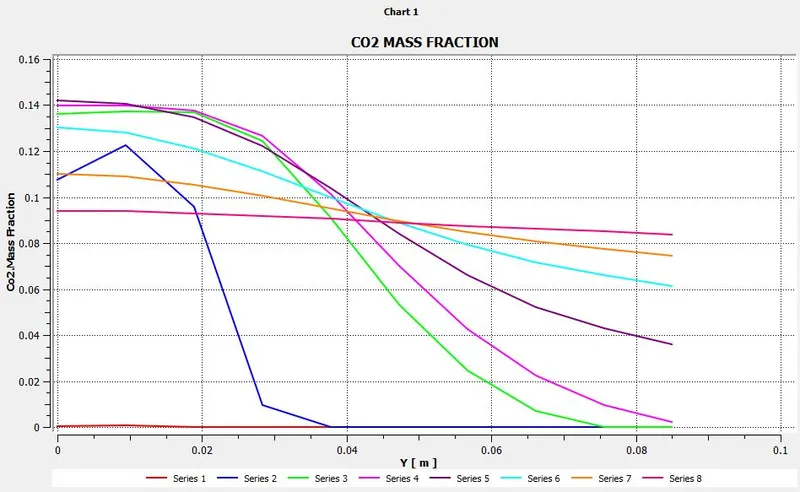
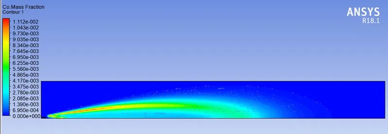
- Perform a combustion simulation on the combustor model and plot the variation of the mass fraction of the different species’ in the simulation using line probes at different locations of the combustor.
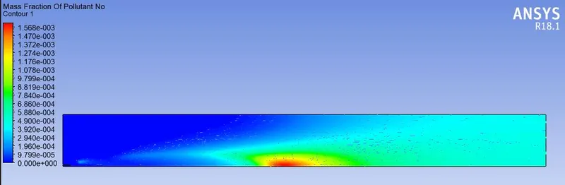
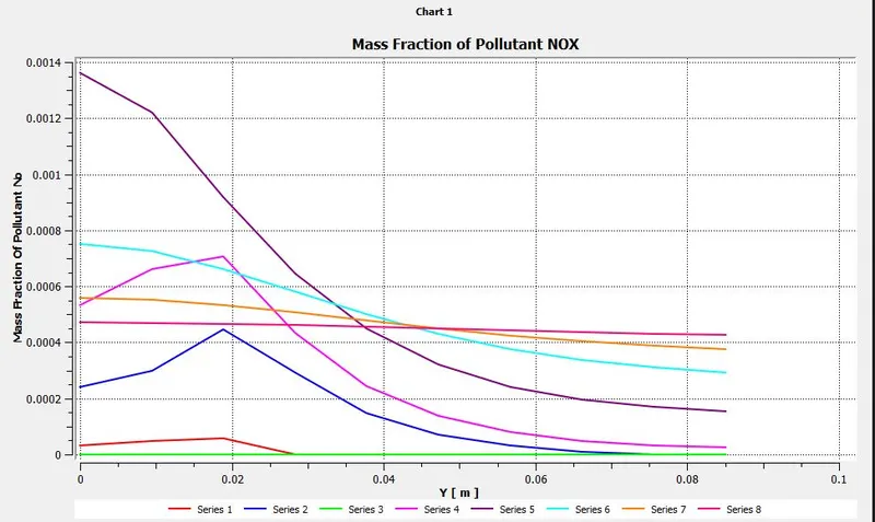
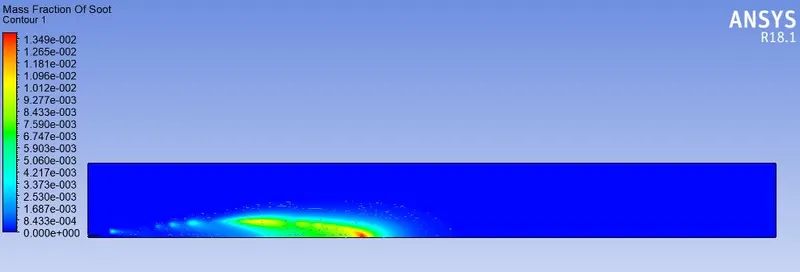
- Plot for CO2, H2O, CH4, N2, O2, NOx emissions & Soot formation.
Combustion:-
- Combustion or burning is a chemical process where any fuel has a reaction with air (oxidant) to produce heat energy. As a product, it is producing gases in the form of smoke.
- Complete combustion is stoichiometric concerning the fuel, where there is no remaining fuel, and ideally, no residual oxidant.
- Basically there are two type combustion one is 'flame mode' in which the thin zone of intense chemical reaction called ‘flame’ exist and another one is 'Non-flame mode' in which volumetric combustion process is exited.
- Thermodynamically, the chemical equilibrium of combustion in air is overwhelmingly on the side of the products. However, complete combustion is almost impossible to achieve, since the chemical equilibrium is not necessarily reached, or may contain unburnt products such as carbon monoxide, hydrogen, and even carbon(soot or ash).
- Mostly the combustion simulation is performed to get the predictions of flow fields and mixing characteristics, Temperature fields, Species Concentrations, Particulates and pollutants etc...
Major pollutants from combustion process.
- Nitrogen Oxide (NOx)
- Soot Particles
- NOx is a Highly regulated pollutant That can result in photochemical smog, This pollutant contributes to ozone depletion and acid rain.
- Soot particles are generally formed due to incomplete combustion or pyrolysis in a rich mixture of a hydrocarbon fuel with strong temperature gradients in the combustion chamber
- Soot observed in domestic fires or chimneys contains few aggregates but large amounts of particulate fragments of coke or char are found. The formation of soot particles is a complex phenomenon: nucleation, surface growth, coalescence, aggregation.
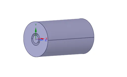
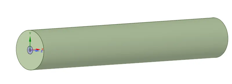
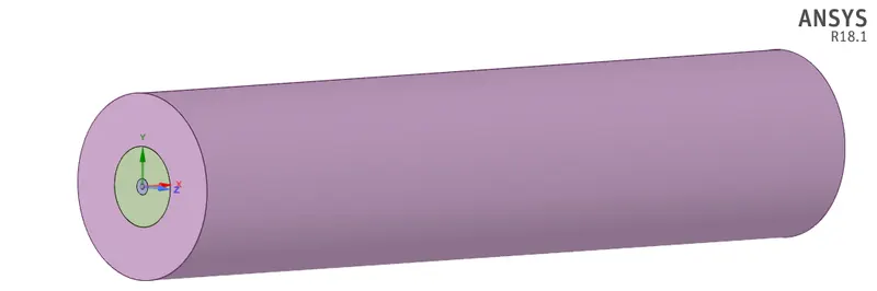
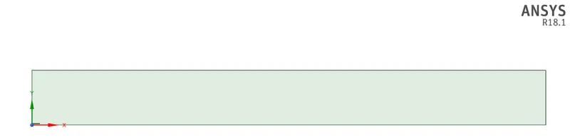
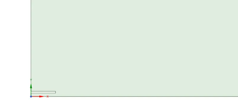
Geometry:-
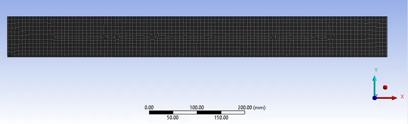
Mesh:-

Named Selections:-
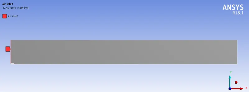
Air Inlet:-
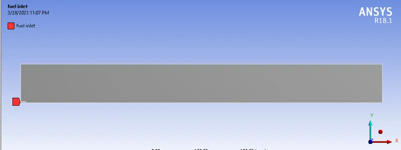
Fuel Inlet:-
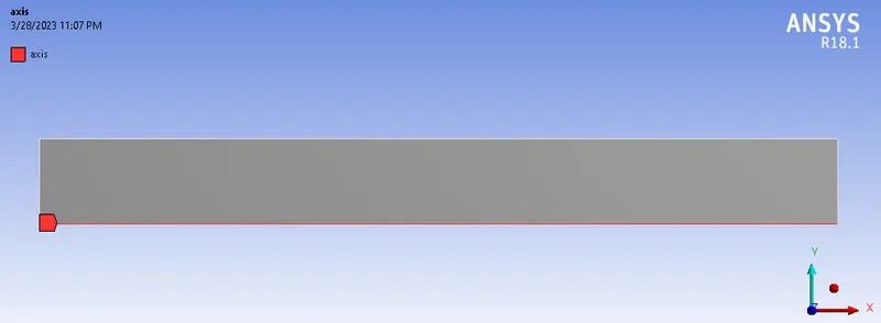
Axis:-
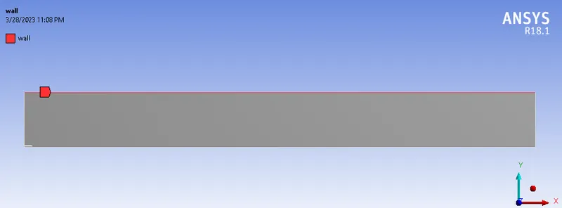
Wall:-
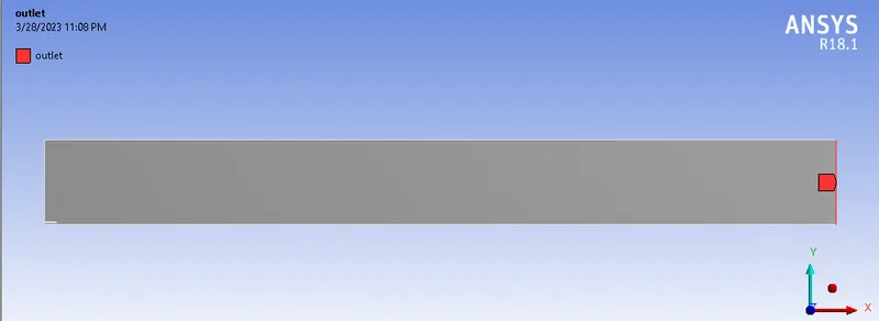
Outlet:-
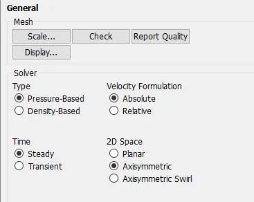
Setup:-
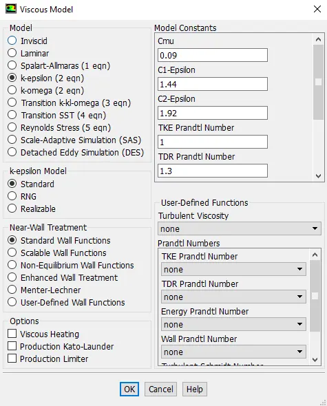
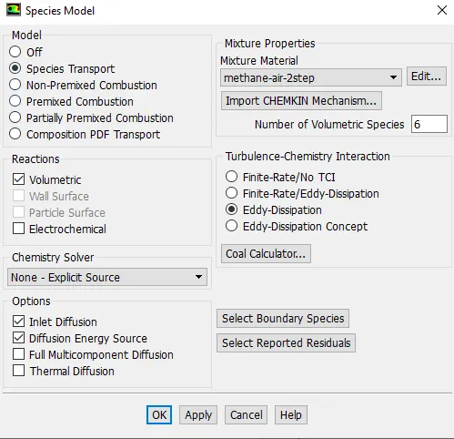
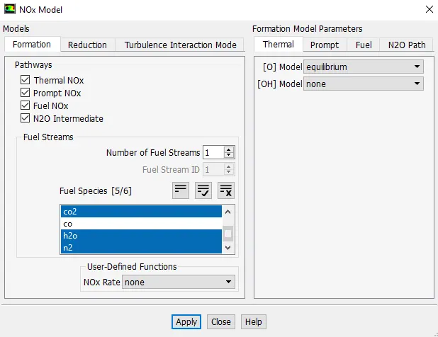
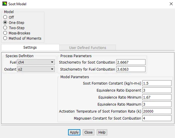
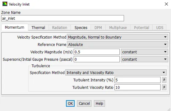
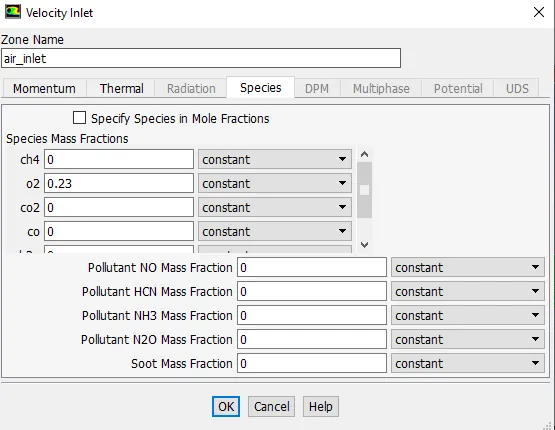
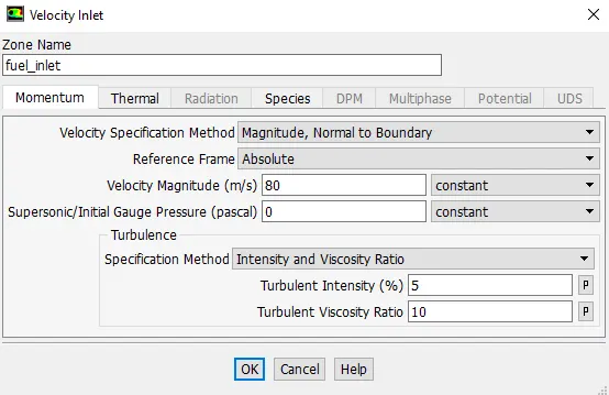
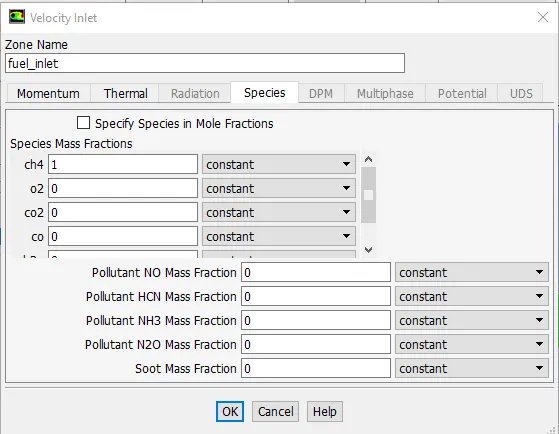
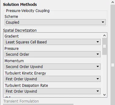
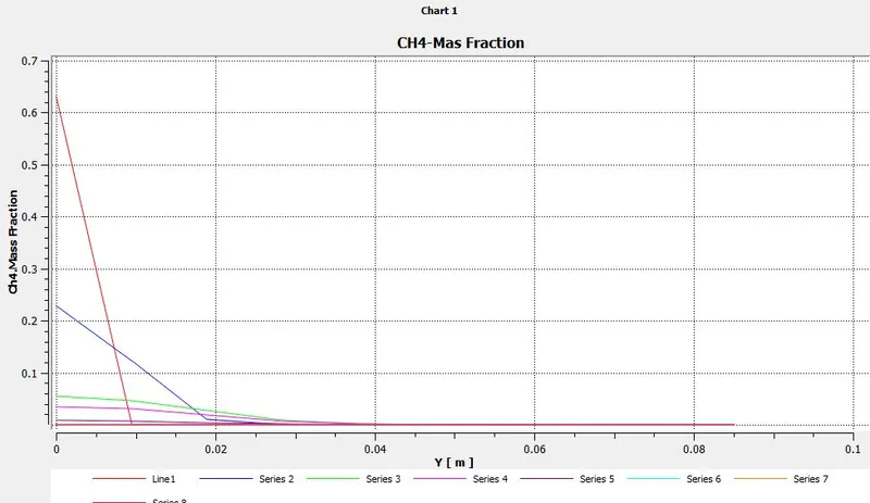
Coordinates of Line probes :-
Line 1 :
Point 1--- x=0.015m y=0m z=0m
Point 2--- x=0.015m y=0.085m z=0m
Line 2 :
Point 1--- x=0.1m y=0m z=0m
Point 2---x=0.1m y=0.085m z=0m
Line 3 :
Point 1---x=0.25m y=0m z=0m
Point 2---x=0.25m y=0.085m z=0m
Line 4 :
Point 1---x=0.3m y=0m z=0m
Point 2---x=0.3m y=0.085m z=0m
Line 5 :
Point 1---x=0.4m y=0m z=0m
Point 2---x=0.4m y=0.085m z=0m
Line 6 :
Point 1---> x=0.5m y=0m z=0m
Point 2---> x=0.5m y=0.085m z=0m
Line 7 :
Point 1---x=0.6m y=0m z=0m
Point 2---x=0.6m y=0.085m z=0m
Line 8 :
Point 1---x=0.79m y=0m z=0m
Point 2---x=0.79m y=0.085m z=0m

Case 1-
Mass Fraction - CH4 =1 ; H2O = 0
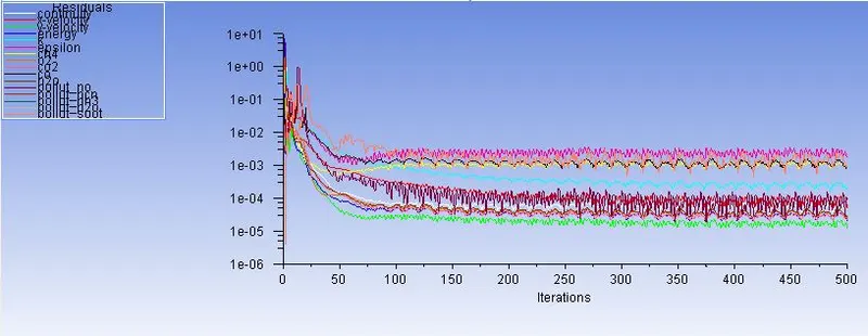
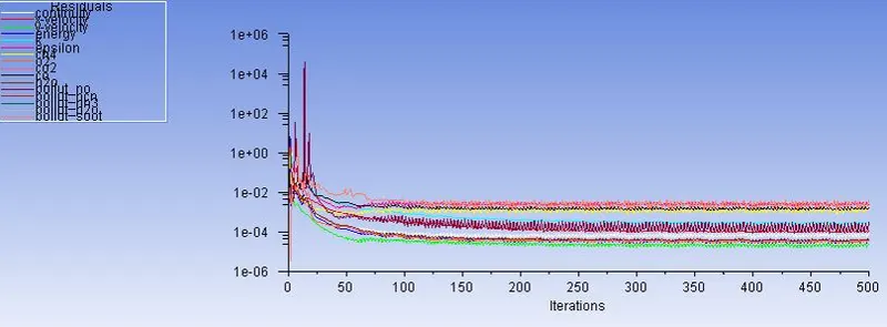
Residual
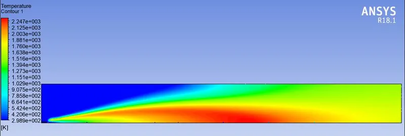
Temperature contour.
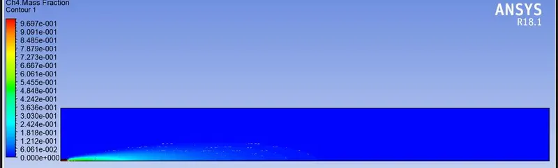
Contour and plot of CH4 mass fraction:
Contour and plot of C02 mass fraction:
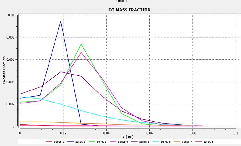
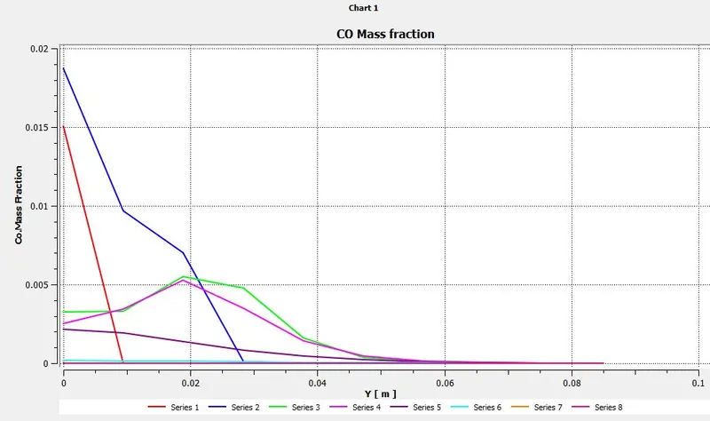
Contour and plot of CO mass fraction:
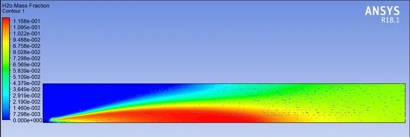
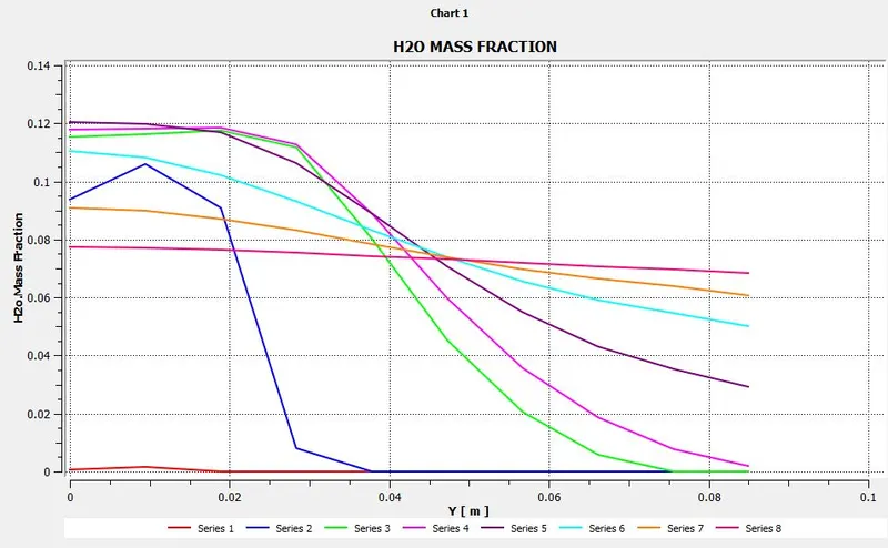
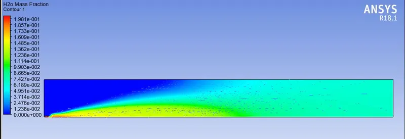
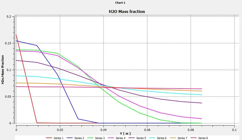
Contour and plot of H2O mass fraction:
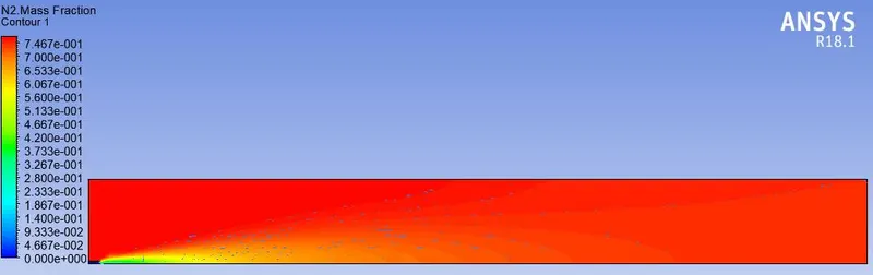
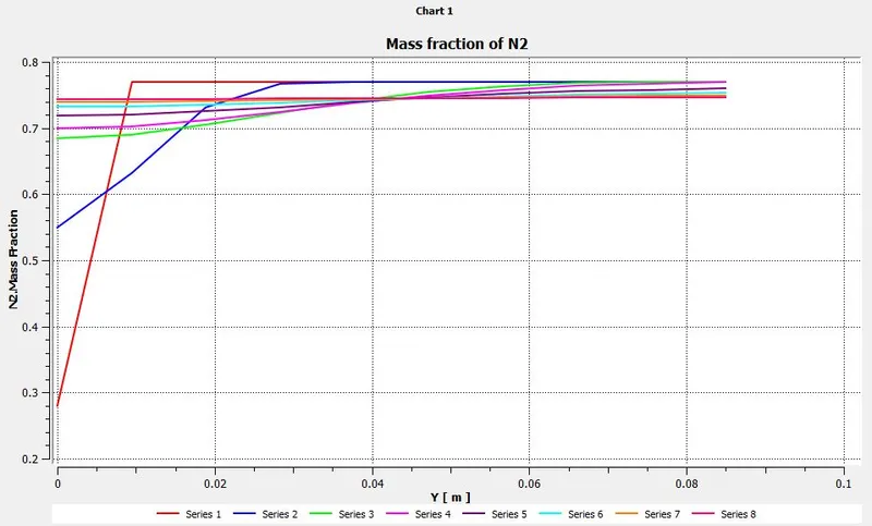
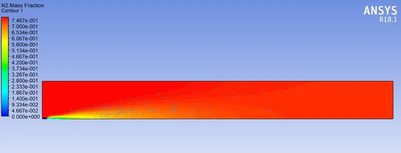
Contour and plot of N2 mass fraction:
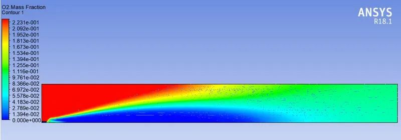
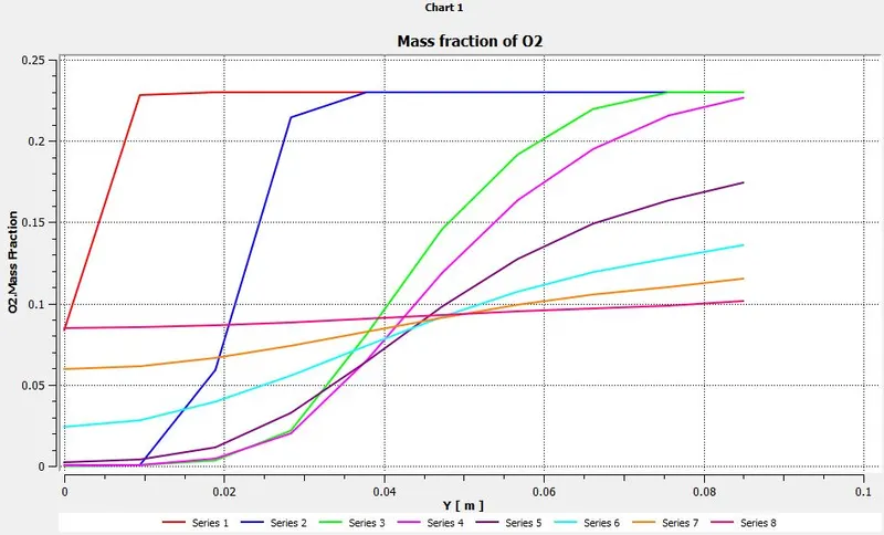
Contour and plot of O2 mass fraction:
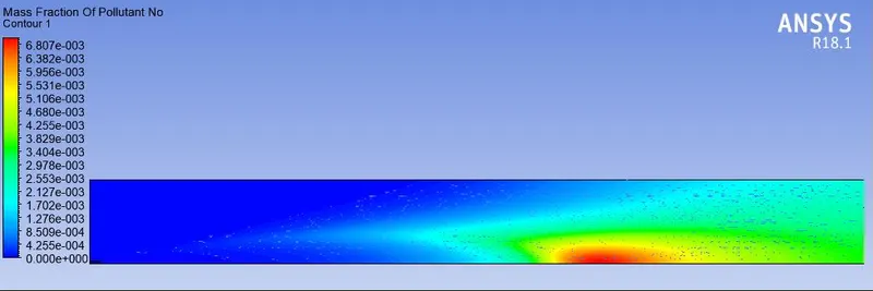
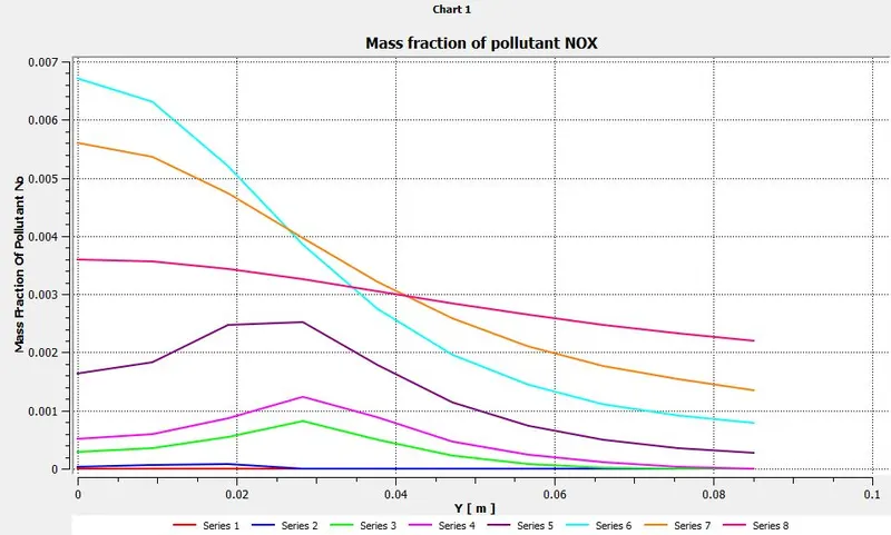
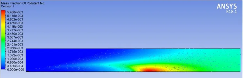
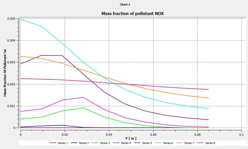
Contour and plot of NOX mass fraction:
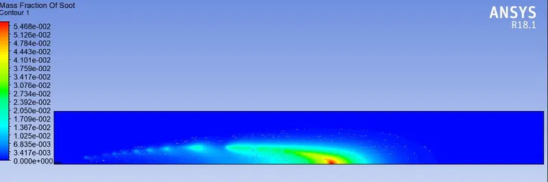
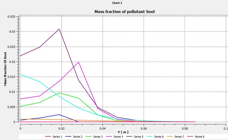
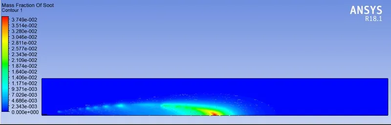
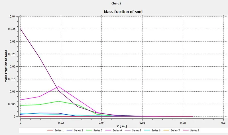
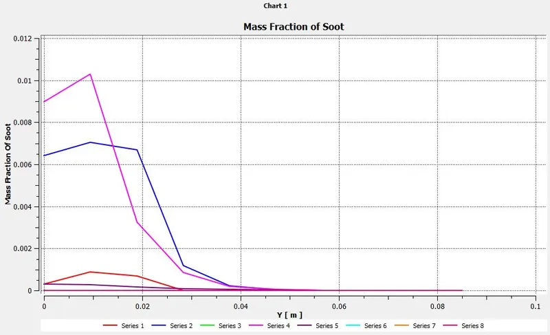
Contour and plot of Soot mass fraction:
Case 2
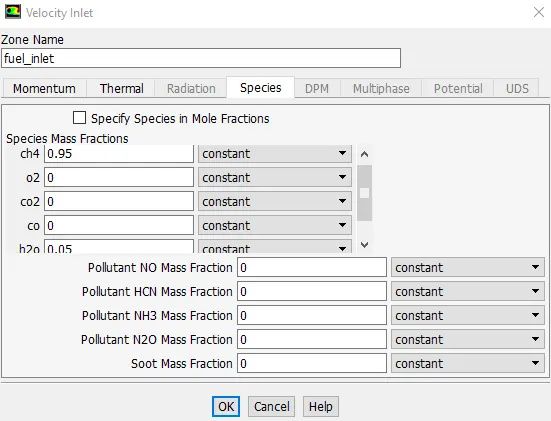
Mass Fraction - CH4 =0.95 ; H2O = 0.05
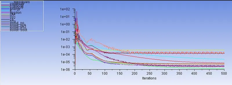
Residual.
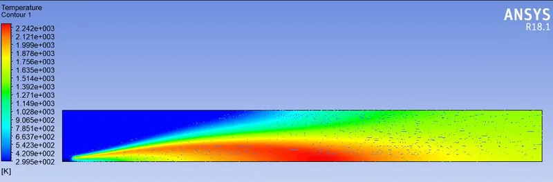
Temperature contour.
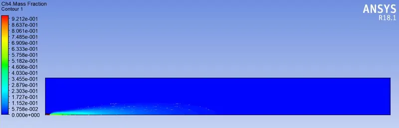
Contour and plot of CH4 mass fraction:
Contour and plot of co2 mass fraction:
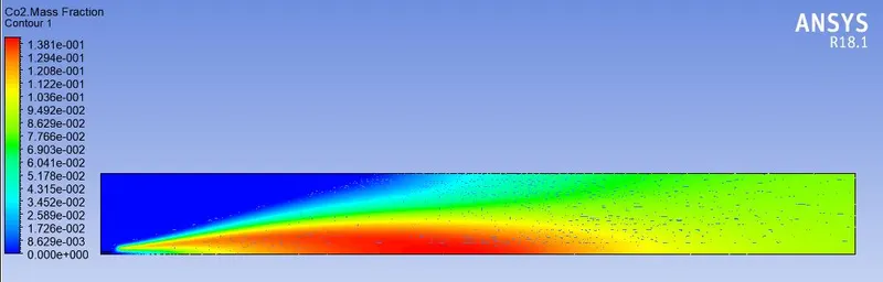
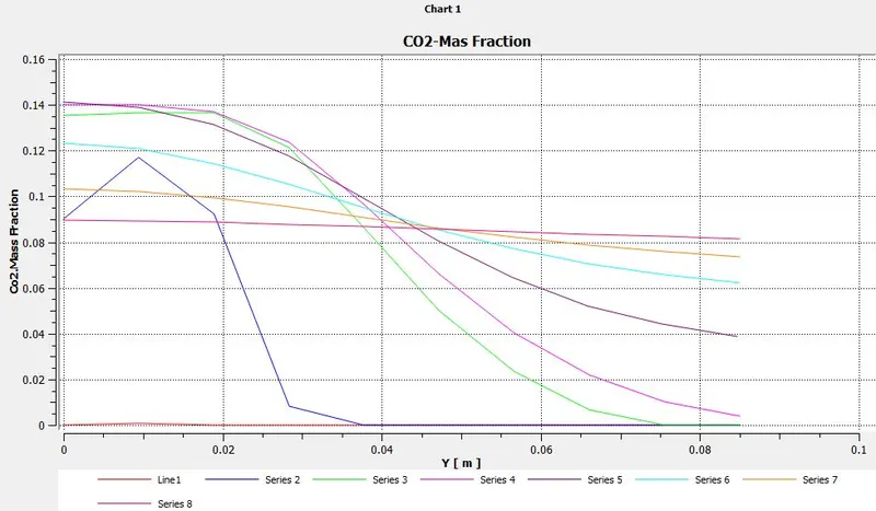
Contour and plot of CO mass fraction:
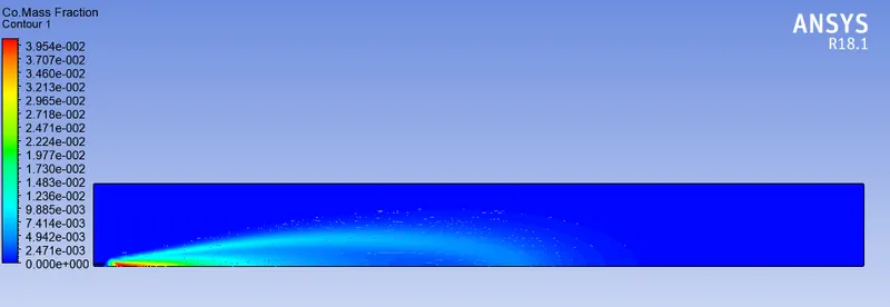
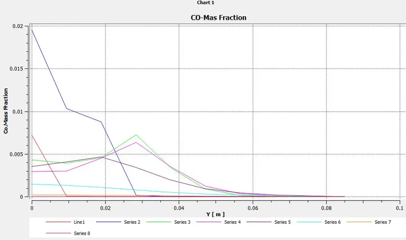
Contour and plot of H2O mass fraction:
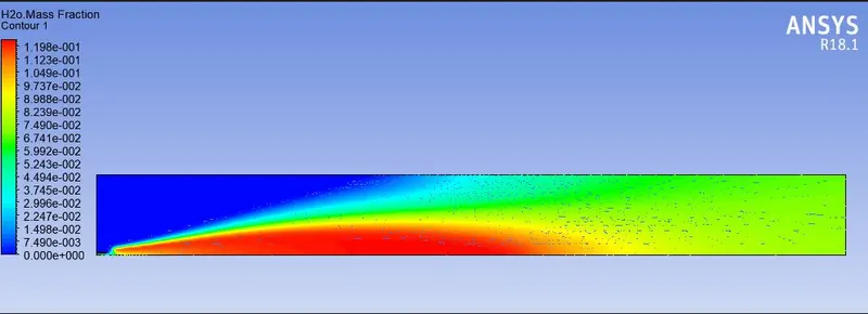
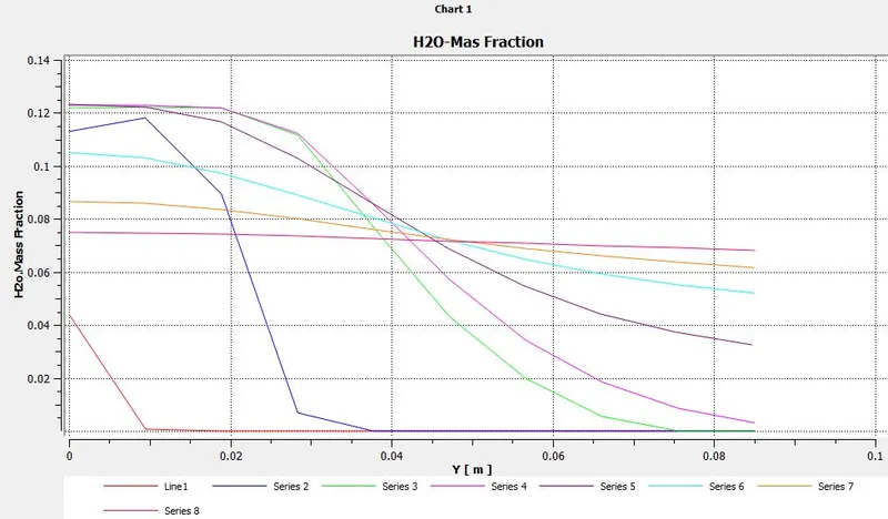
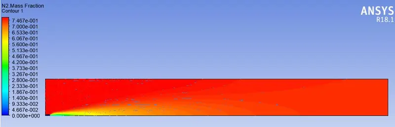
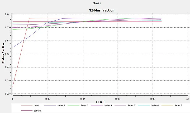
Contour and plot of N2 mass fraction:
Contour and plot of O2 mass fraction:
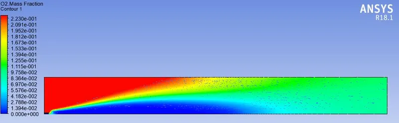
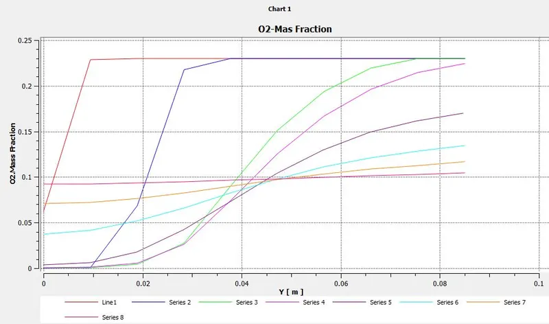
Contour and plot of NOX mass fraction:
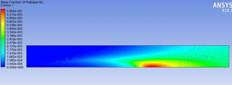

Contour and plot of Soot mass fraction:
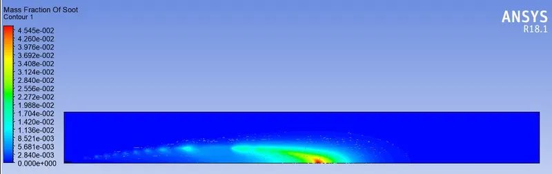
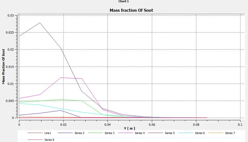
Case 3
Mass Fraction - ch4 =0.9 ; h2o = 0.1:
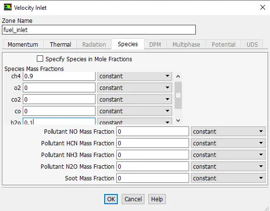
Residual.
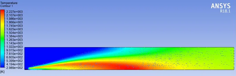
Temperature contour.
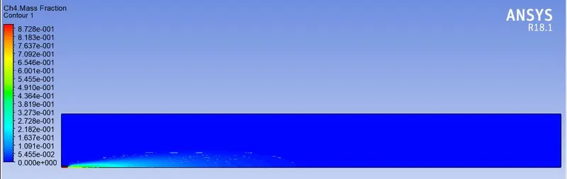
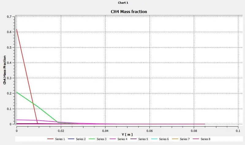
Contour and plot of CH4 mass fraction:
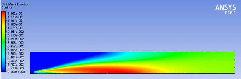
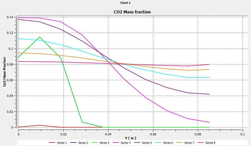
Contour and plot of CO2 mass fraction:
Contour and plot of CO mass fraction:
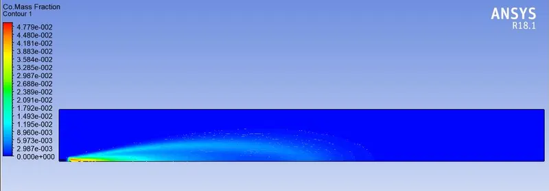
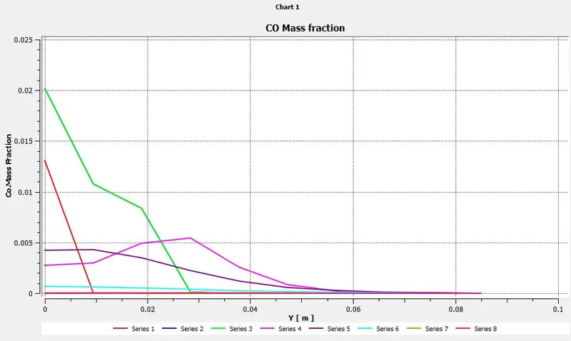
Contour and plot of H2O mass fraction:
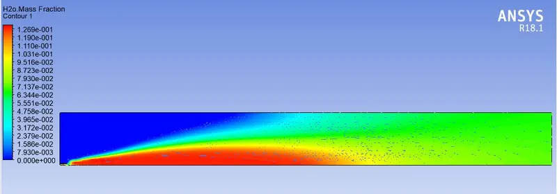
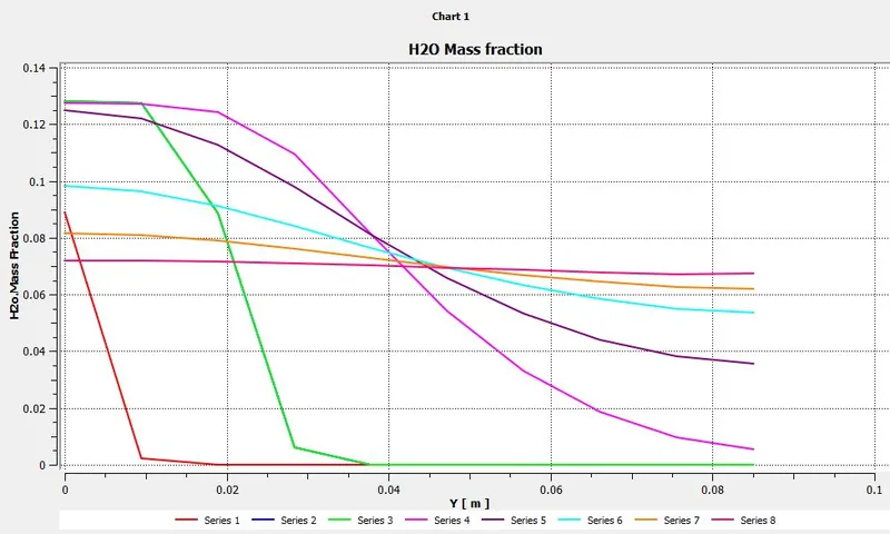
Contour and plot of N2 mass fraction:
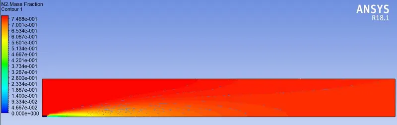
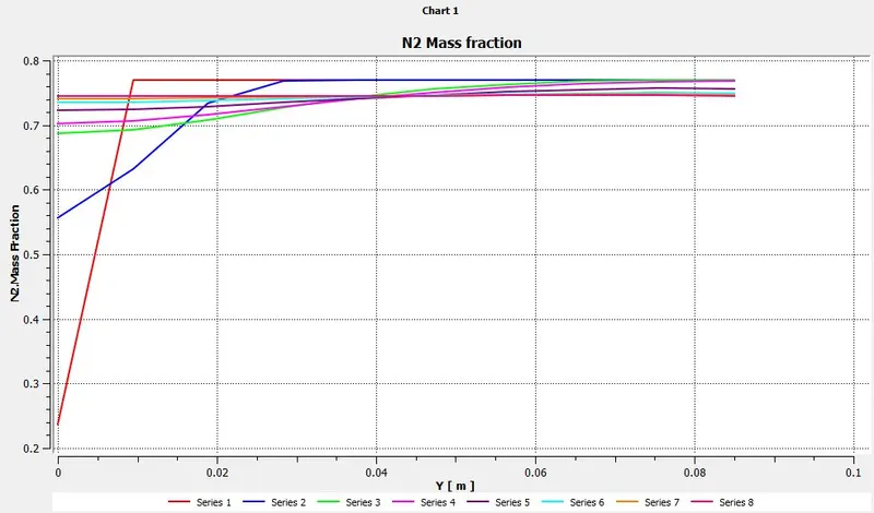
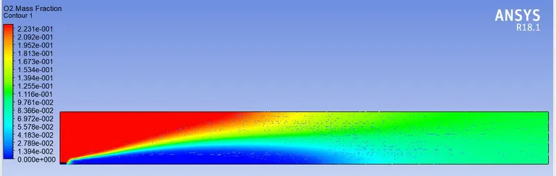
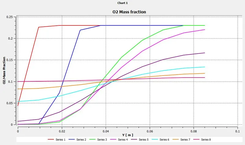
Contour and plot of O2 mass fraction:
Contour and plot of NOX mass fraction:
Contour and plot of Soot mass fraction:
Case 4
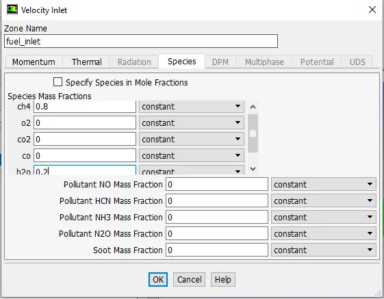
Mass Fraction - CH4 =0.8 ; H2O = 0.2:
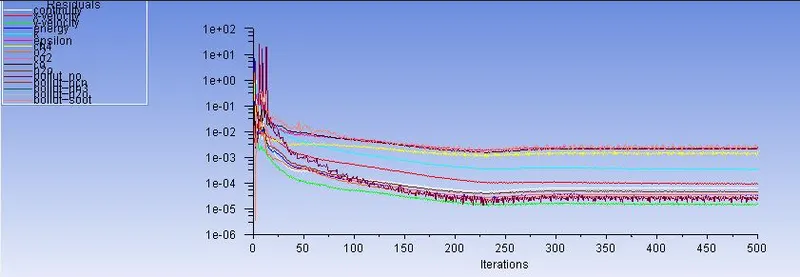
Residual.
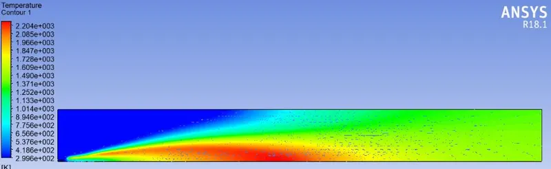
Temperature contour.
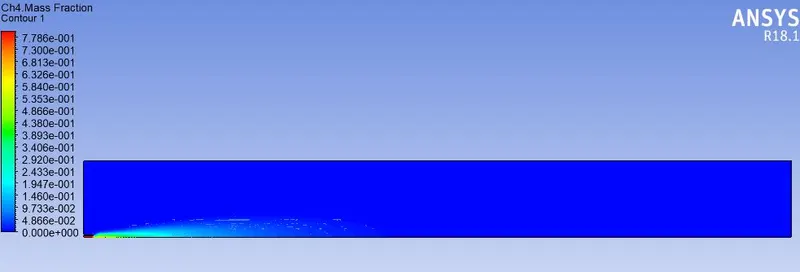
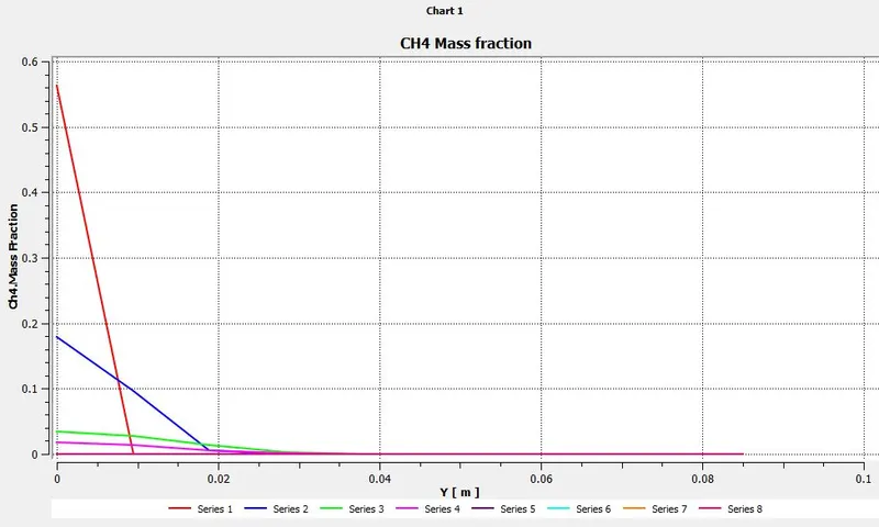
Contour and plot of CH4 mass fraction:
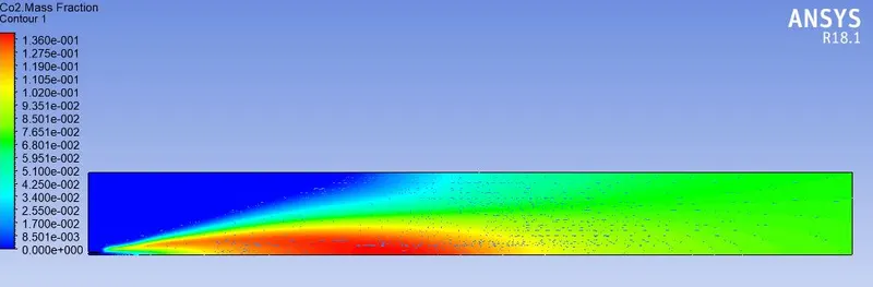
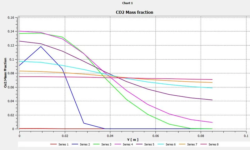
Contour and plot of C02 mass fraction:
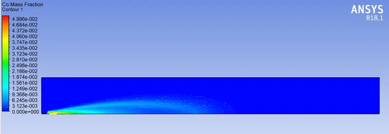
Contour and plot of CO mass fraction:
Contour and plot of H2O mass fraction:
Contour and plot of N2 mass fraction:
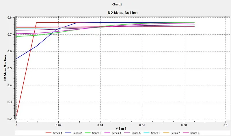
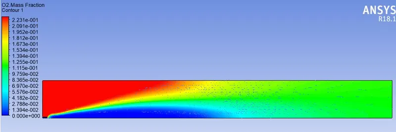
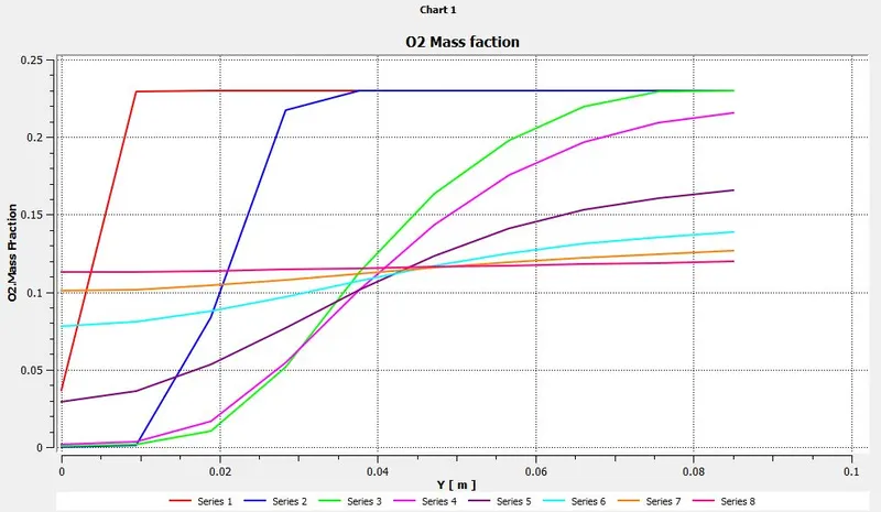
Contour and plot of O2 mass fraction:
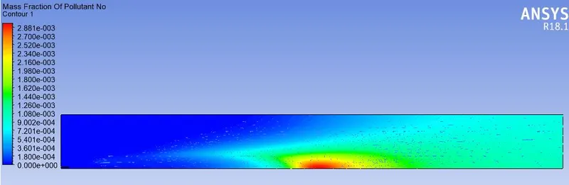
Contour and plot of NOX mass fraction:
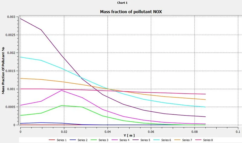
Contour and plot of Soot mass fraction:
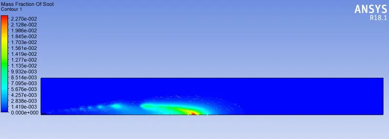
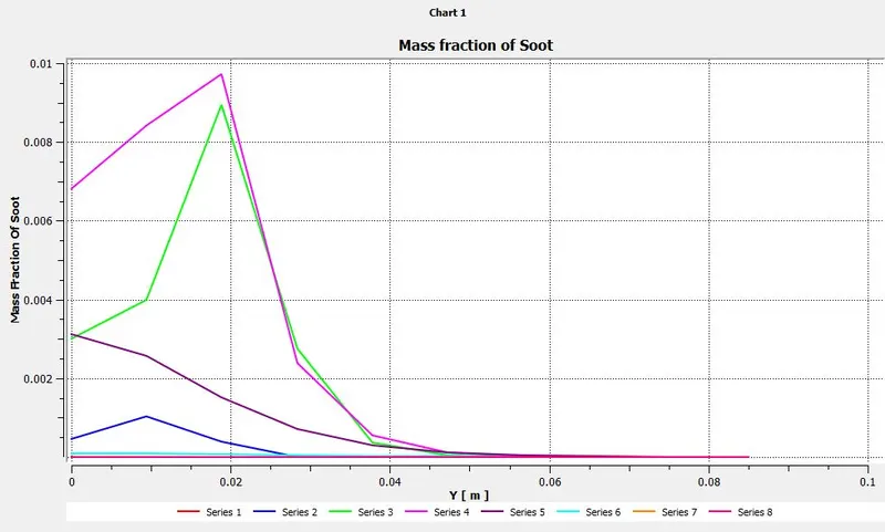
Case 5
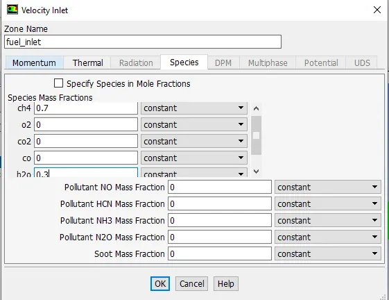
Mass Fraction - CH4 =0.7 ; H20 = 0.3:
Residual.
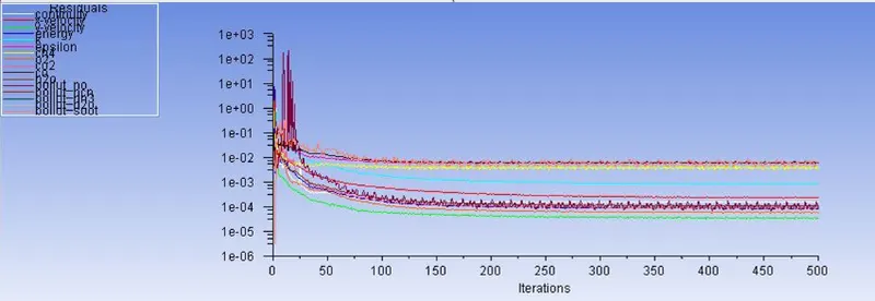
Temperature contour.
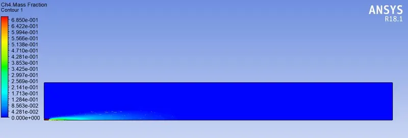
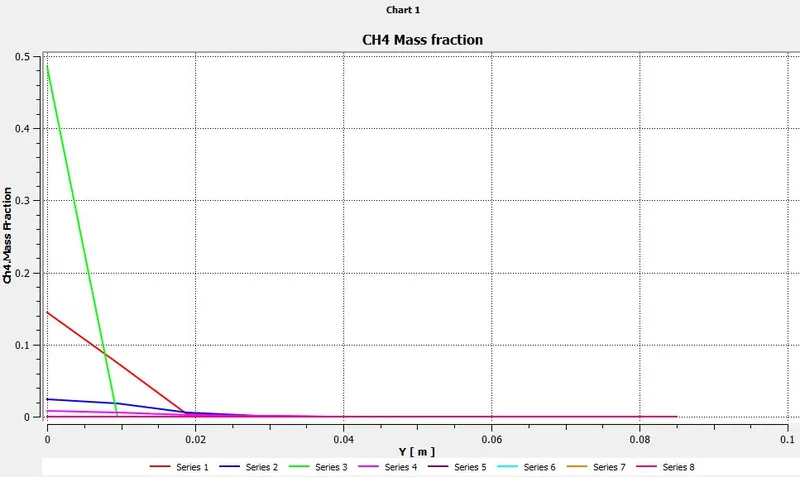
Contour and plot of CH4 mass fraction:
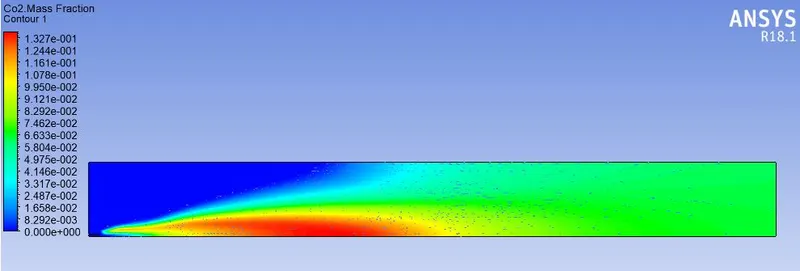
Contour and plot of C02 mass fraction:
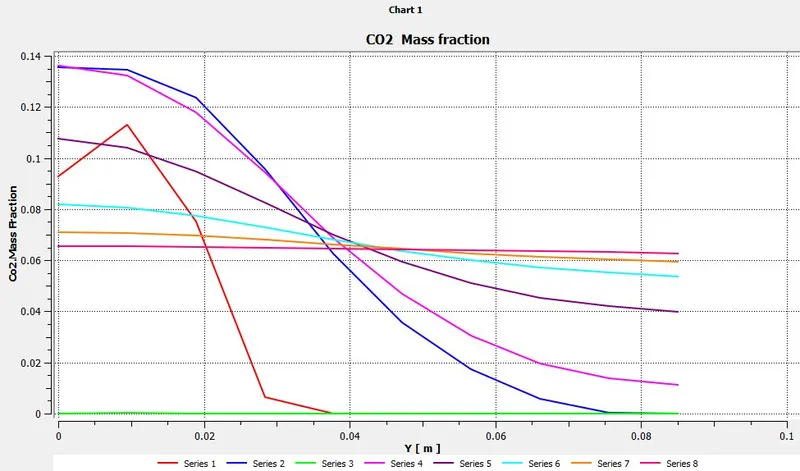
Contour and plot of CO mass fraction:
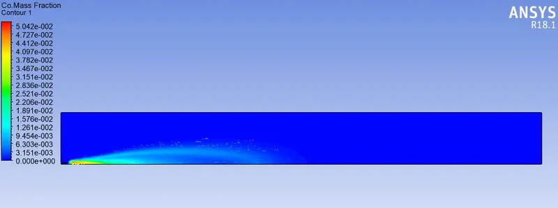
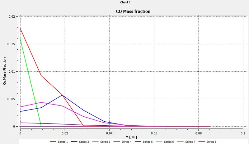
Contour and plot of H2O mass fraction:
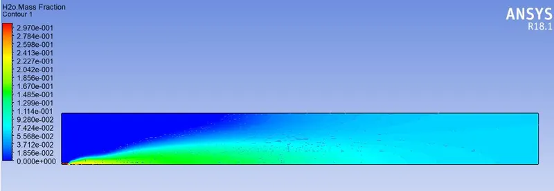
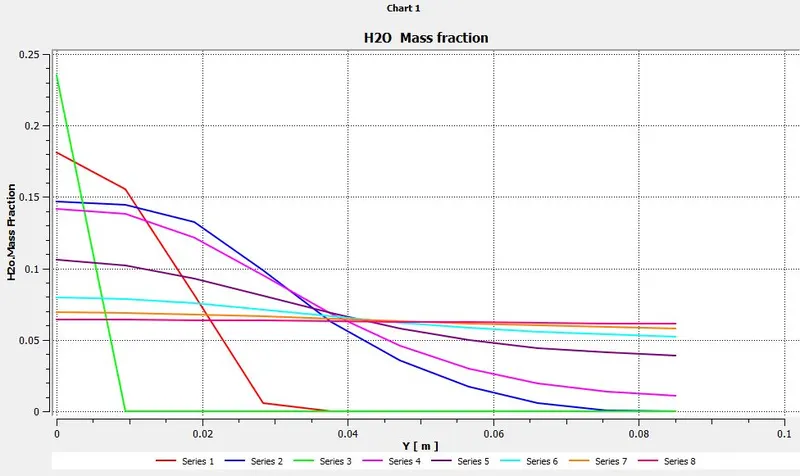
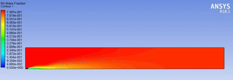
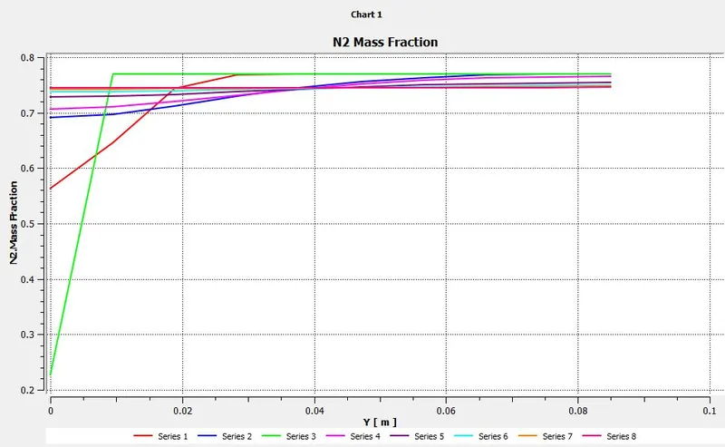
Contour and plot of N2 mass fraction:
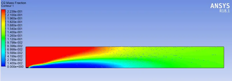
Contour and plot of O2 mass fraction:
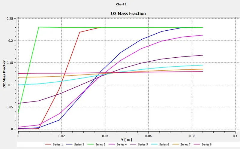
Contour and plot of NOX mass fraction:
Contour and plot of Soot mass fraction:
Conclusion:-
- Eddy - dissipation model(ie;-Turbulence Chemistry Interaction) helps us to model combustion via turbulence mixing without the presence of an ignition source.
- Diluting of fuel with H2O reduce the formation of harmful pollutants such as NOx and soot at the outlet.
- Addition of water will lead to reduce the temperature of combustor.
- As the soot value decreases with dilution of fuel,then there is less wastage of fuel, that means a complete combustion occurs.
- Hence a combustion simulation on the combustor model has been done and the values are compared for different fractions water added.