Week 10 - Simulating Combustion of Natural Gas.
Simulation on Natural Gas
AIM: To perform a combustion simulation on the combustor model and plot the variation of the mass fraction of the different species
OBJECTIVE:
Simulating using line probes at different locations of the combustor and to plot for CO2, H2O, CH4, N2, O2, NOx emissions & Soot formation.
To add the water content in the fuel from 5% to 30% by mole and observe the effect of it on the results.
INTRODUCTION:
Natural gas is the cleanest of all the fossil fuels, as evidenced in the Environmental Protection Agency Composed primarily of methane. The main products of the combustion of natural gas are carbon dioxide and water vapor, the same compounds we exhale when we breathe.
Mass Fraction: The ratio of the mass of a component in a mixture to the total mass of the mixture is known as mass fraction.
Mole Fraction: The ratio of a number of molecules of one component of solution or other mixture to the total number of moles representing all of the components.
Eddy dissipation model:
The eddy dissipation model, based on the work of Magnussen of turbulent-chemistry reaction model. Most fuels are fast burning and the overall rate of reaction is controlled by turbulence mixing. In the non-premixed flames, turbulence slowly mixes the fuel and oxidizer into the reaction zones where they burn quickly. In premixed flames, the turbulence slowly mixes cold reactants and hot products into the reaction zones where the reaction occurs rapidly. In such cases, the combustion is said to be mixing-limited, and the complex and often unknown chemical kinetics can be safely neglected. In this model, the chemical reaction is governed by large-eddy mixing time scale. Combustion initiates whenever there is turbulence present in the flow. It does not need an ignition source to initiate the combustion. This type of model is valid for the non-premixed combustion, but for the premixed flames the reactant is assumed to burn at the moment it enters the computation model, which is a shortcoming of this model as in practice the reactant needs some time to get to the ignition temperature to initiate the combustion.
Nitrogen Oxide (NOx) emissions:
Nitrogen dioxide is an irritant gas, which at high concentrations causes inflammation of the airways. When nitrogen is released during fuel combustion it combines with oxygen atoms to create nitric oxide (NO). This further combines with oxygen to create nitrogen dioxide (NO2). Nitric oxide is not considered to be hazardous to health at typical ambient concentrations, but nitrogen dioxide can be. Nitrogen dioxide and nitric oxide are referred to together as oxides of nitrogen (NOx).
NOx gases react to form smog and acid rain as well as being central to the formation of fine particles (PM) and ground-level ozone, both of which are associated with adverse health effects.
Soot formations:
Soot forms when hydrocarbon fuels such as oil, natural gas, and wood are burned. Soot particles form when gaseous molecules are heated to high temperatures, and they don't easily turn back into gaseous molecules the way water droplets do when they are heated. Soot as an airborne contaminant in the environment has many different sources, all of which are results of some form of pyrolysis. They include soot from coal-burning, internal-combustion engines, power-plant boilers, hog-fuel boilers, ship boilers, central steam-heat boilers, waste incineration, local field burning, house fires, forest fires, fireplaces, and furnaces. These exterior sources also contribute to the indoor environment sources such as smoking of plant matter, cooking, oil lamps, candles, quartz/halogen bulbs with settled dust, fireplaces, exhaust emissions from vehicles, and defective furnaces.
Modelling of combustion reaction in a software is difficult and need to take care for species which are taking part in reaction and its products. The combustion CFD model comprises of chemical kinetics and similarly achieving reacting flow mixture environment. Considering chemical kinetics, it is also important to have properly defined physical model with simulation to get the maximum out of process. Computational fluid dynamics of combustion model should be capable of enough to provide information related to species concentration, their volumetric generation or diffusion rate and changes in the system parameters like enthalpy, temperature and mixture density. The similar model should be good enough to solve the general transport equations for fluid flows and heat transfer as well as additional equations of combustion chemistry and chemical kinetics incorporated as per simulation environment details.
Procedure/ steps to simulation:
1. Geometry Creation:
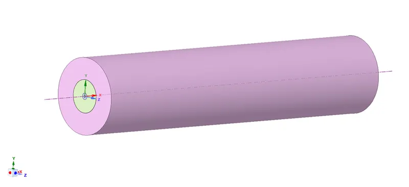
Import the 3D model from file. We have to observe that the 3d model is containing 3 parts in it.
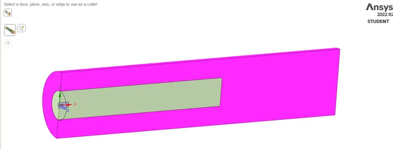
From this 3D module we are not able simulate the simulation coz it needs more mesh on body. Then we used the split body option to cut/split the body by 3/4th of full body. We have to split body in half condition and have to make sure that the split body is in XY direction. The below images shows the geometry creation of combustor.
3D Model of Combustor:
Half split body of combustor:
3/4th Portion of combustion model:
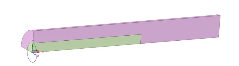
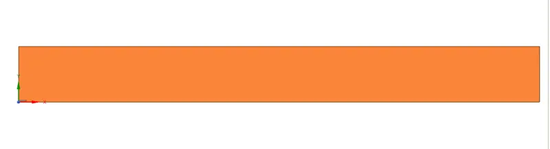
After split body we have combine the surfaces with each other to create the 2D geometry. Then to create the 2D geometry we have copy it and paste it into new window in XY plane only ( coz we are simulating with the consideration of direction as in XY direction) for 2D geometry creation.
2D Geometry of combustor:
2. Meshing:
The 2D geometry from spaceclaim will move to mesh section. Here we to allow the refined mesh size to the 2D geometry. For consideration of condition of flow in geometry we have to name selections such as Air-inlet, Fuel-inlet, wall, axis (which is center of model), outlet.
Then the mesh size is given as 0.003m (3mm), and we allowed the capture proximity with gap factor of 3 (To give the gap between the cells).
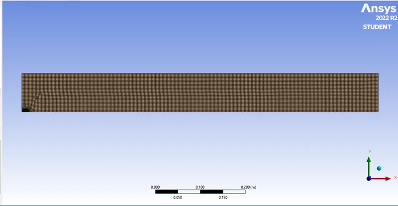
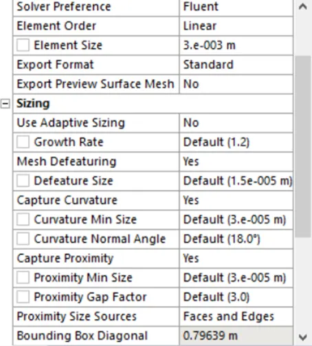
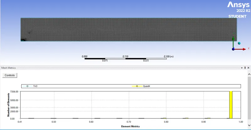
With Mesh size of 0.003m (3mm), we get elements of 7575 nodes of 7901and the element quality around 0.95 to 1. Since it is good quality.
Setup:
For the simulation of combustion model we to setup some conditions and parameters. For the particular combustion model simulation we enabled the pressure based solver with axisymmetric planner (The model is in axisymmetric portion) and with steady state time solver.
For allowing of water we enable the gravitational acceleration in negative y-direction -9.81.
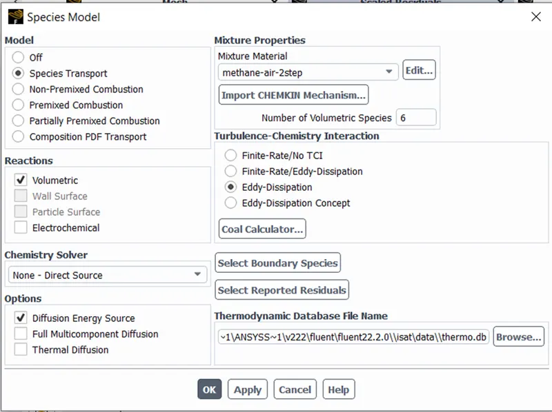
We have specify the species model as below image as for model allow species transport coz the species flow in zone were the reaction from species in volumetric zone. We use the mixture properties as methane-air-2step ( coz it allows to add water in fuel or air). We are running the simulation with turbulence chemistry as eddy-dissipation while using diffusion energy source.
After setting up species select materials to provide the simulate the simulation in good manner, then select boundary condition allow air-inlet at velocity-inlet with velocity of 0.5 m/s with 300k temperature and species as 23% of O2.
For fuel-inlet allow velocity-inlet with velocity of 80m/s, 300k temperature and species of 1 (100%) as CH4 and keep all species as 0.
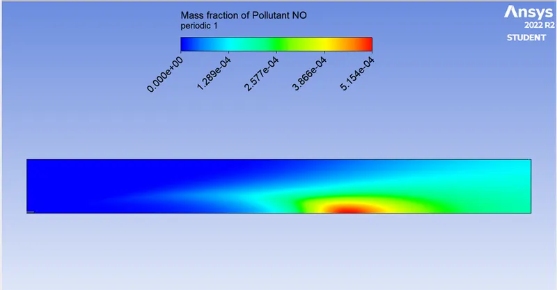
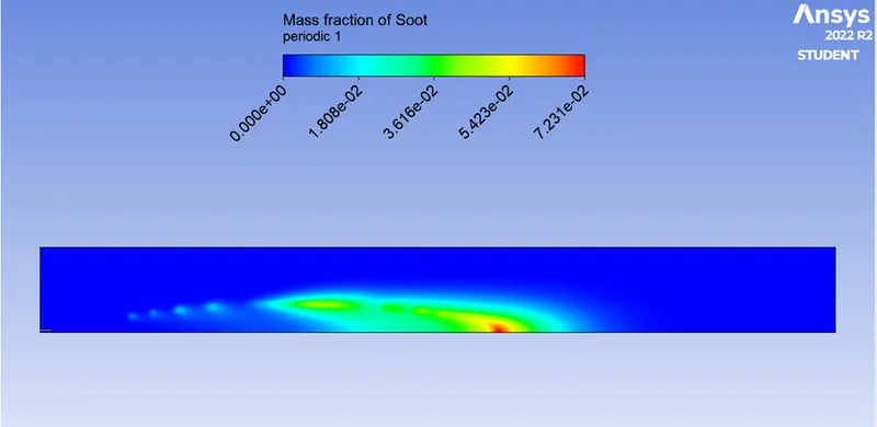
According to problem condition we allow the NOx model enable with pathway as thermal NOx and Prompt NOx and species as CH4. And enable the soot model for one-step with particular species.
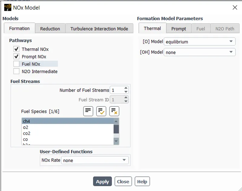
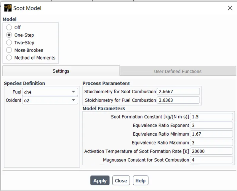
Initializing the simulation with hybrid initialization with coupled solution method.
PART 1:
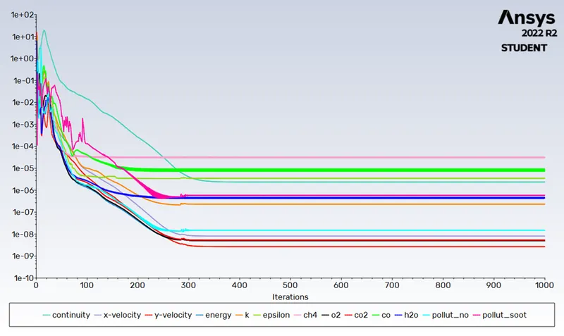
Residual plot:
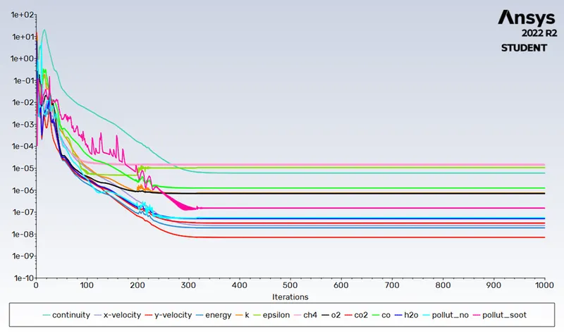
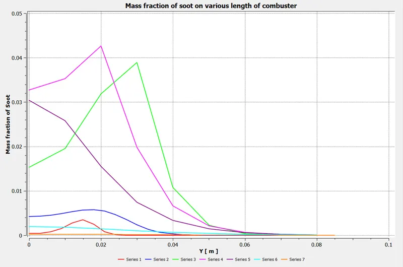
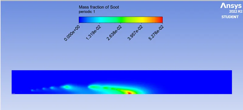
We get Mass pollutant of NOx as 0.000655 and Mass Fraction of Soot as 1.947e-5.
Post-Process:
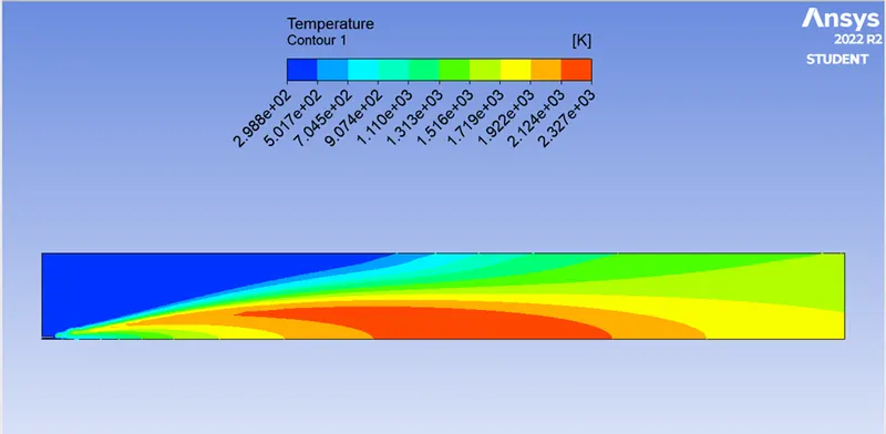
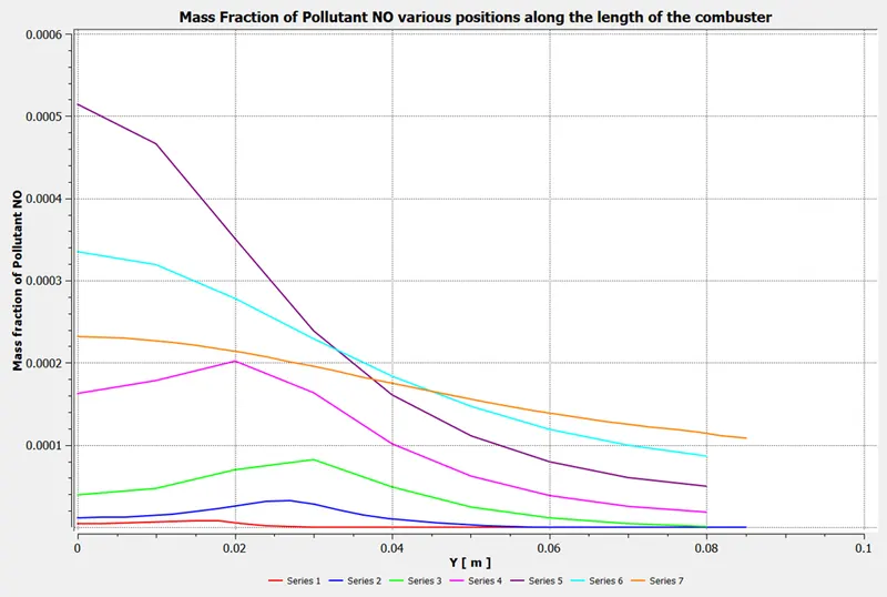
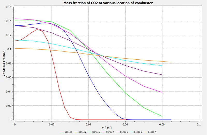
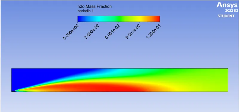
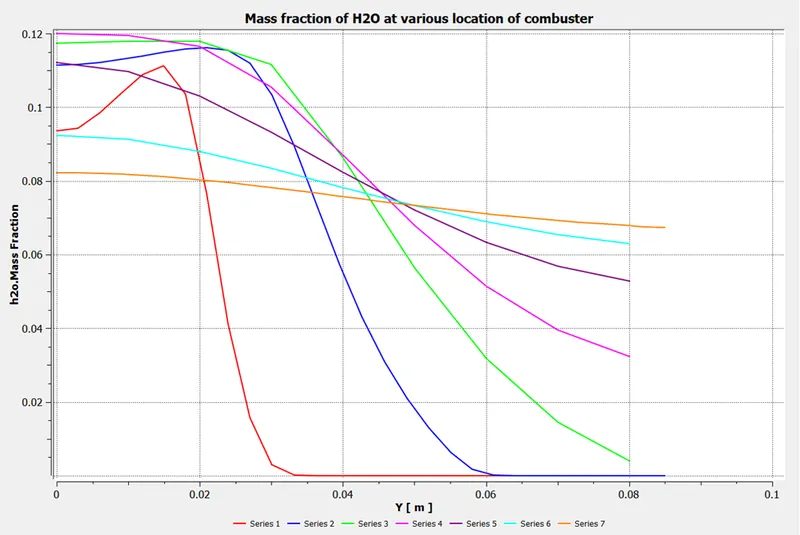
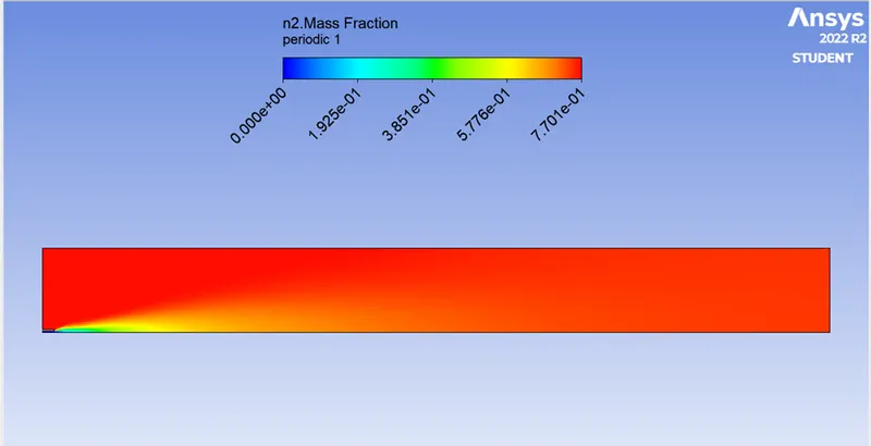
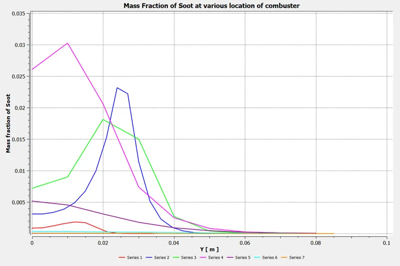
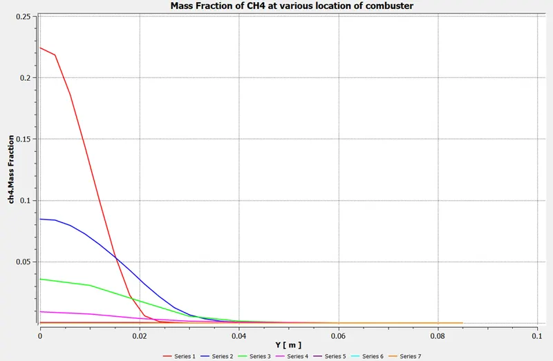
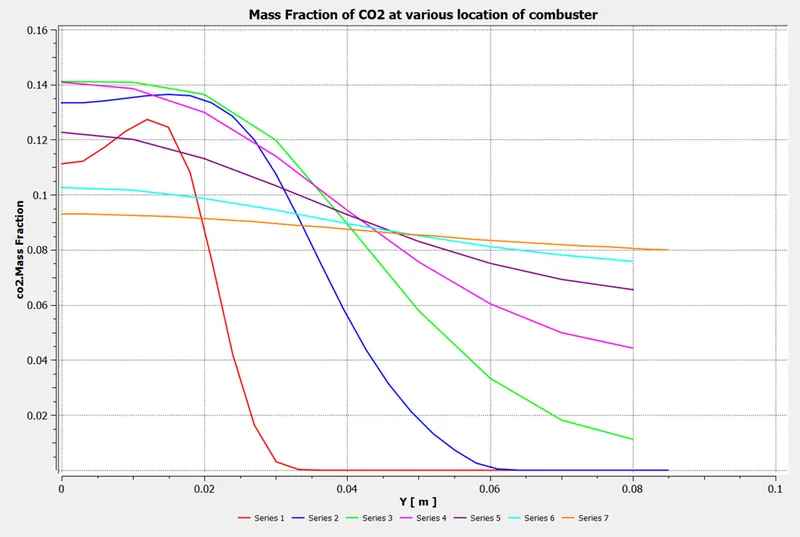
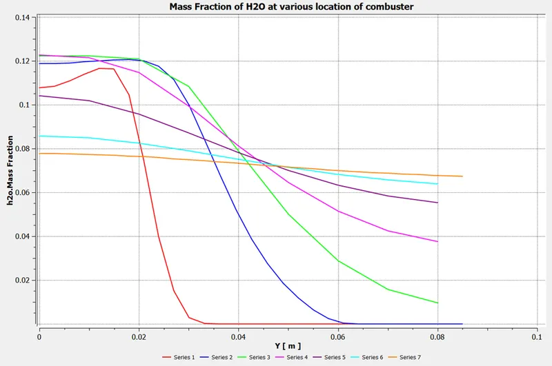
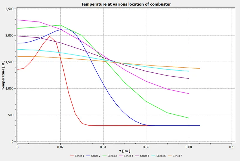
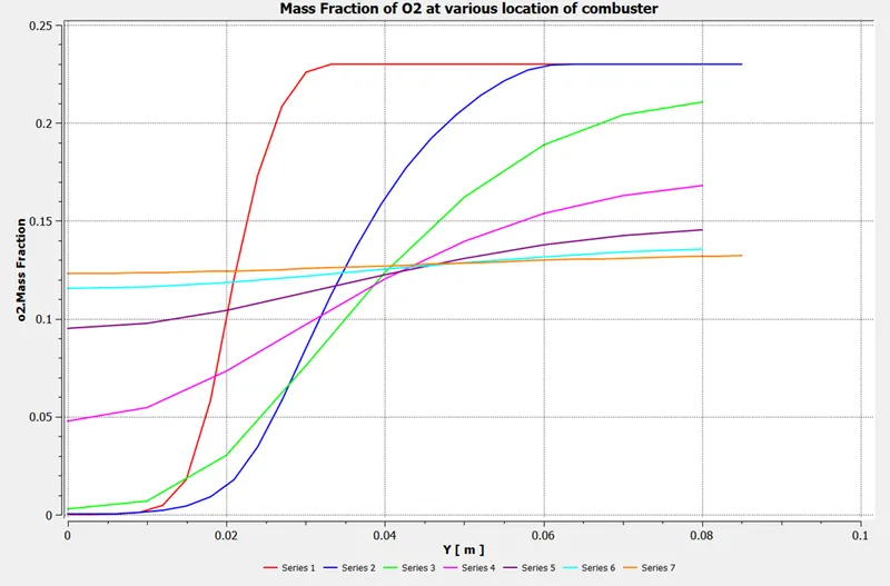
We have check the results of simulation in post-process with required species reaction in volumetric zone and we can find the flow of species in terms of rection (eddy dissipation) flow by plot at various locations by allowing the probes.
Temperature:
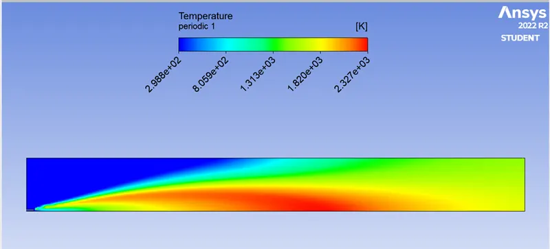
Temperature contour:
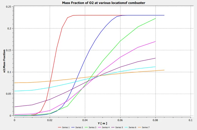
Line probes at various locations on combustor
|
Probes |
Point 1 (x, y, z) |
Point 2 (x, y, z) |
|
Line 1 |
0.1, 0.09, 0 |
0.1, 0, 0 |
|
Line 2 |
0.2, 0.09, 0 |
0.2, 0, 0 |
|
Line 3 |
0.3, 0.09, 0 |
0.3, 0, 0 |
|
Line 4 |
0.4, 0.09, 0 |
0.4, 0, 0 |
|
Line 5 |
0.5, 0.09, 0 |
0.5, 0, 0 |
|
Line 6 |
0.6, 0.09, 0 |
0.6, 0, 0 |
Mass Fraction of NOx pollutant:
Mass Fraction of Soot:
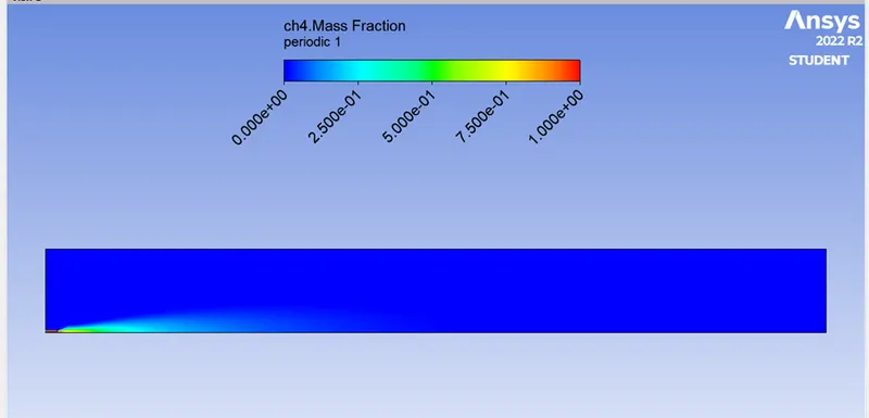
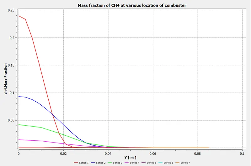
Mass Fraction of CH4:
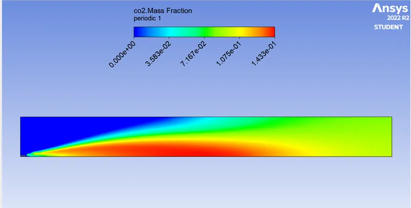
Mass Fraction of CO2:
Mass Fraction of H2O:
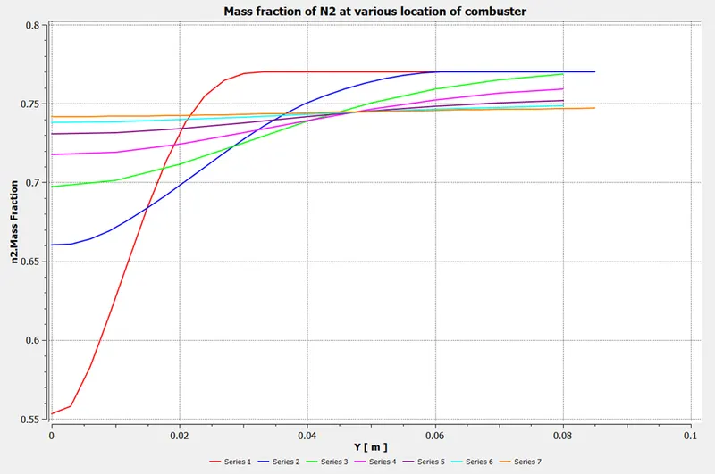
Mass Fraction of N2:
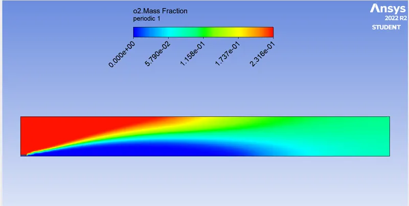
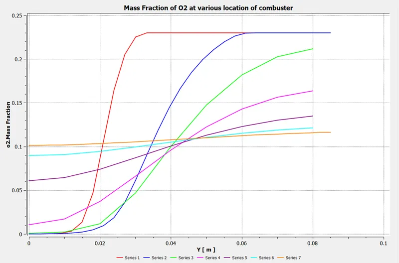
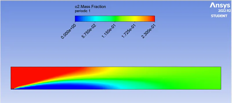
Mass fraction of O2:
Part 2:
Form view of part 2 condition of problem we to allow the water with fuel inlet by mixing with CH4. Coz the Nox and soot is getting formed at the outlet of the combustor. Such formation has harmful effects on the environment and humans. The stringent government norms also demand the least formation of Nox and soot and to satisfy those requirements, we need to check the effect of adding the water in the fuel. So we added the water (H2O) to observe the effect on result.
Case 1:
Adding 5% of Water to Fuel CH4
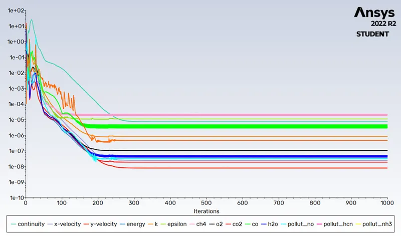
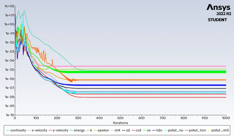
Residual plot:
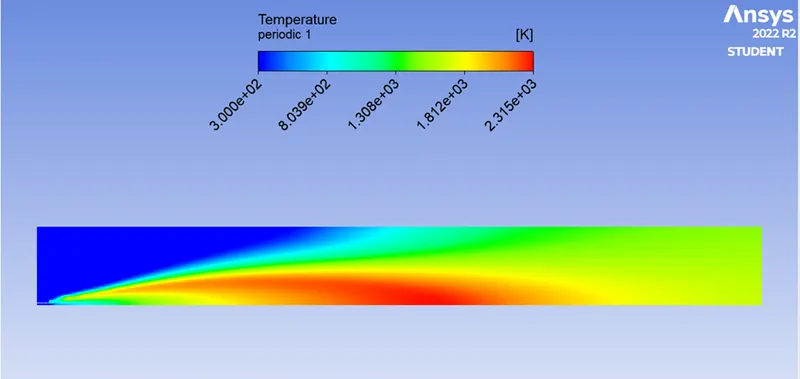
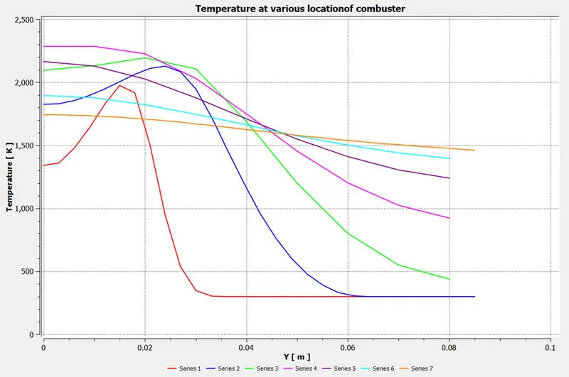
Temperature plot:
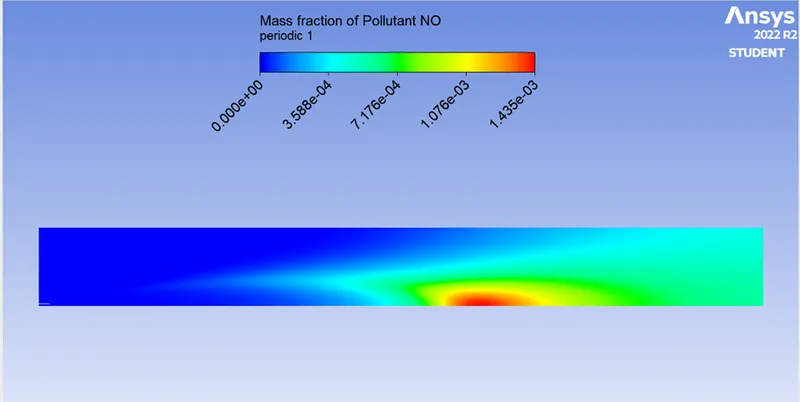
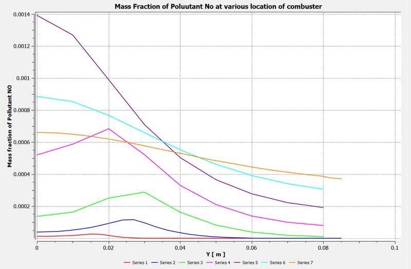
Mass Fraction of Pollutant NOx:
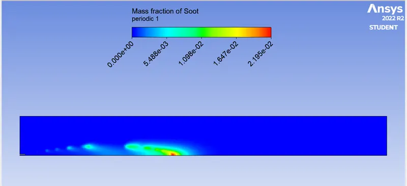
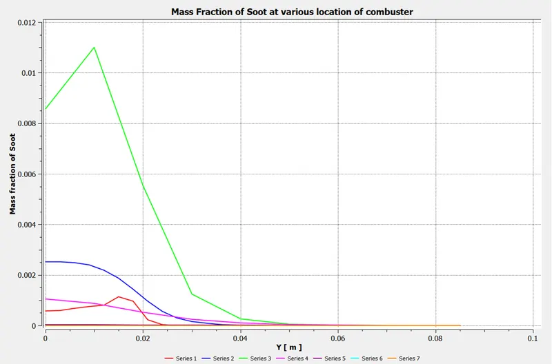
Mass Fraction of Soot:
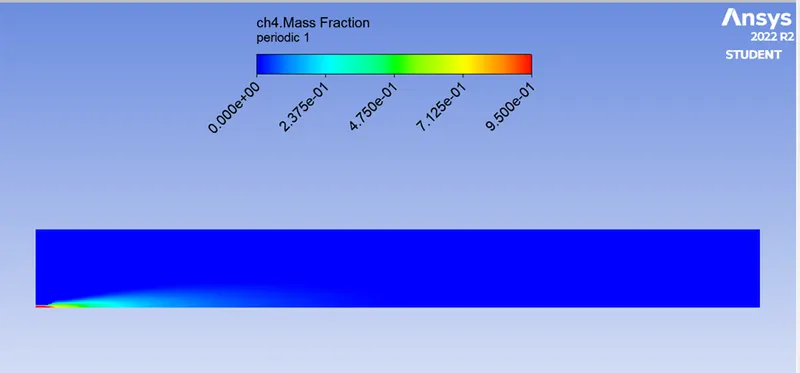
Mass Fraction of CH4:
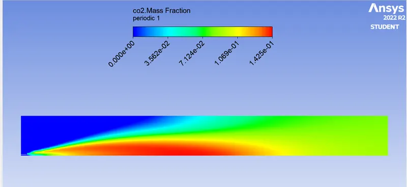
Mass Fraction of CO2:
Mass Fraction of H2O:
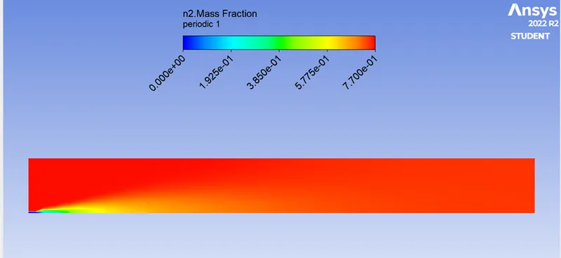
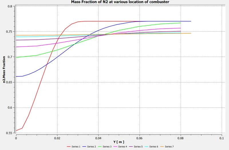
Mass Fraction of N2:
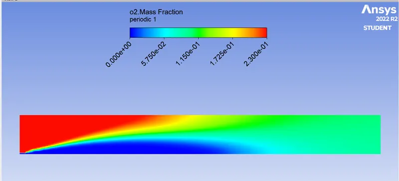
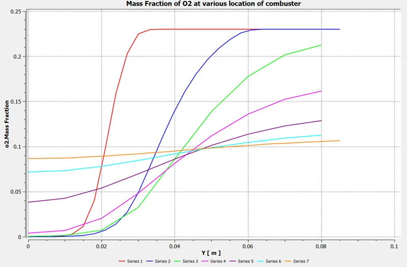
Mass Fraction of O2:
CASE 2:
Adding 15% of Water to Fuel CH4
Residual plot:
Post-process:
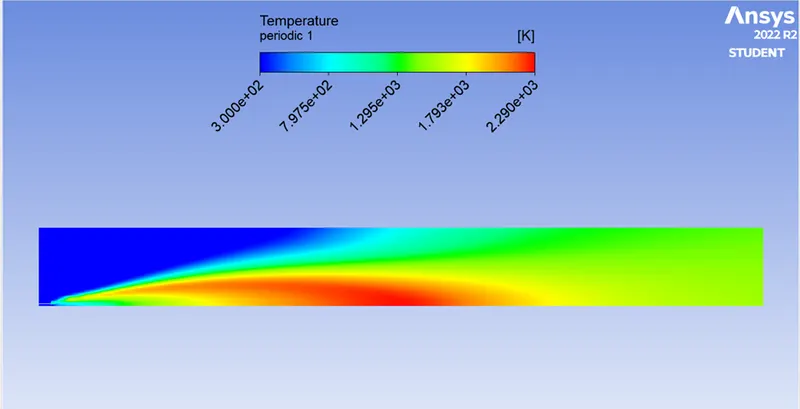
Temperature plot:
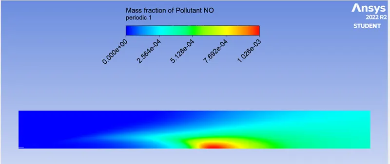
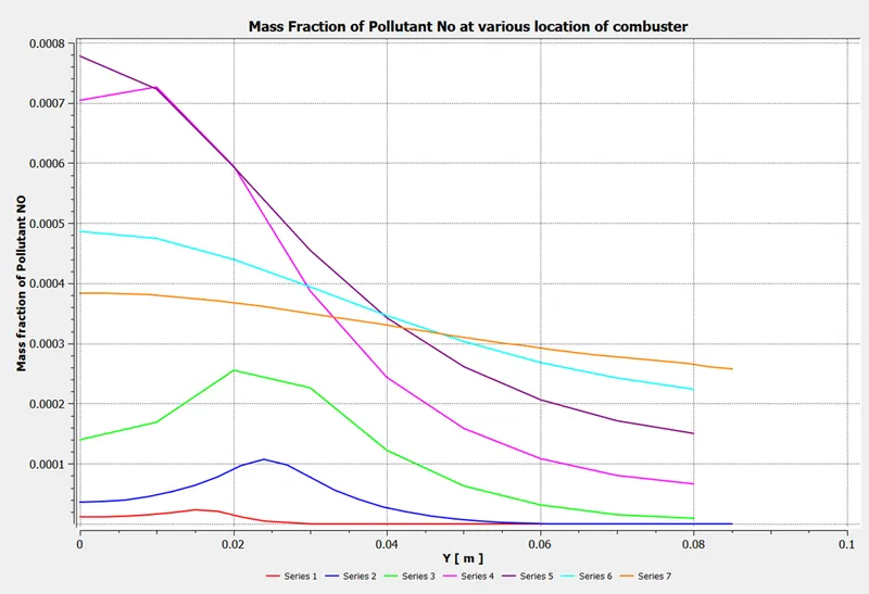
Mass Fraction of Pollutant NOx:
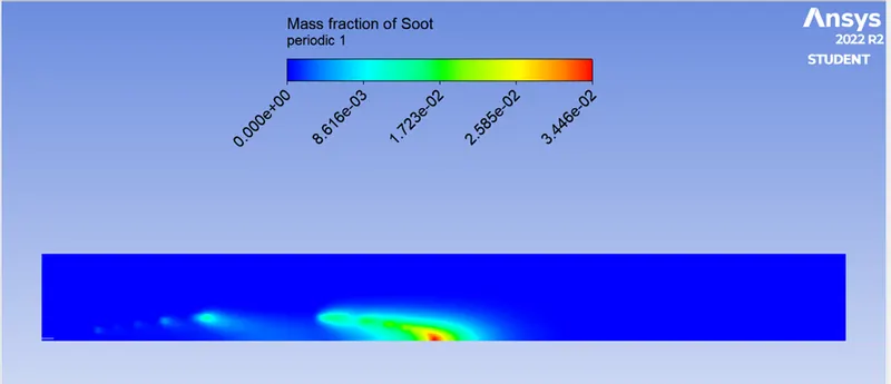
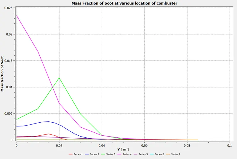
Mass Fraction of Soot:
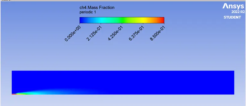
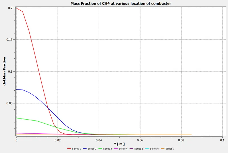
Mass Fraction of CH4:
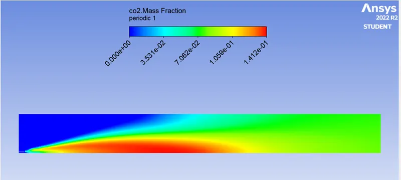
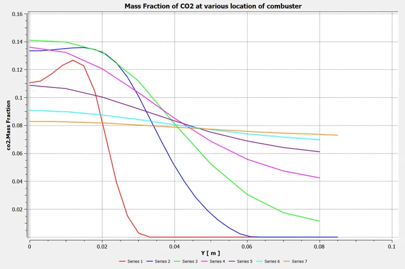
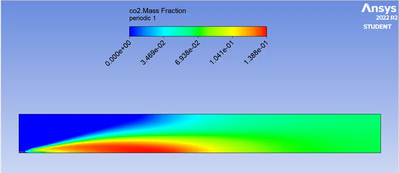
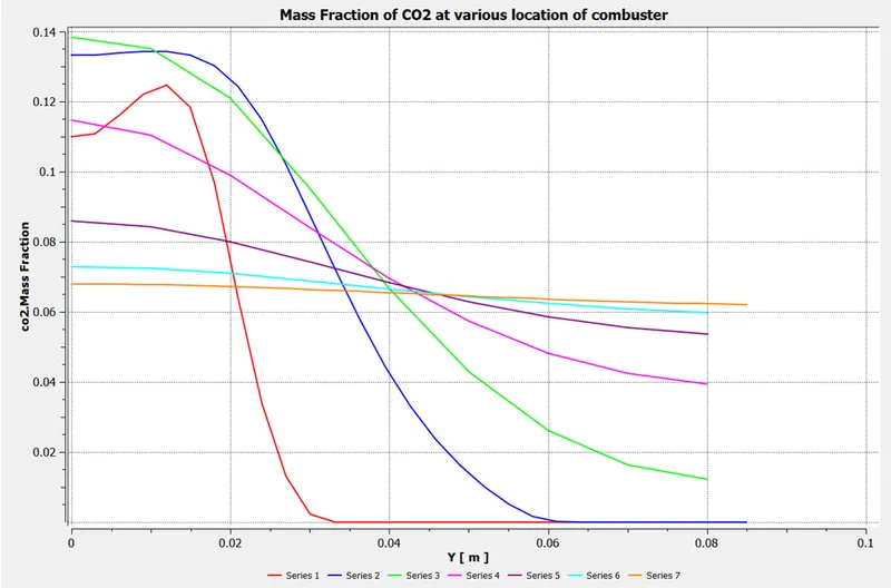
Mass Fraction of CO2:
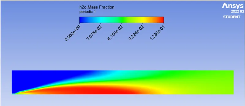
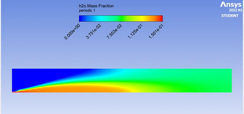
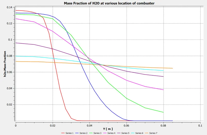
Mass Fraction of H2O:
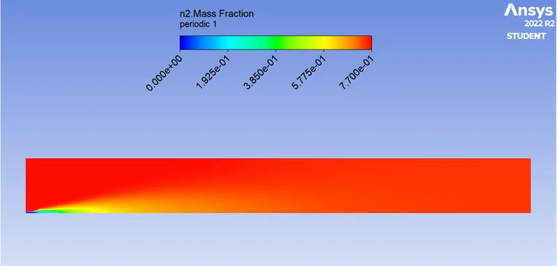
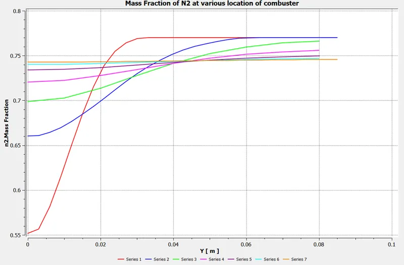
Mass Fraction of N2:
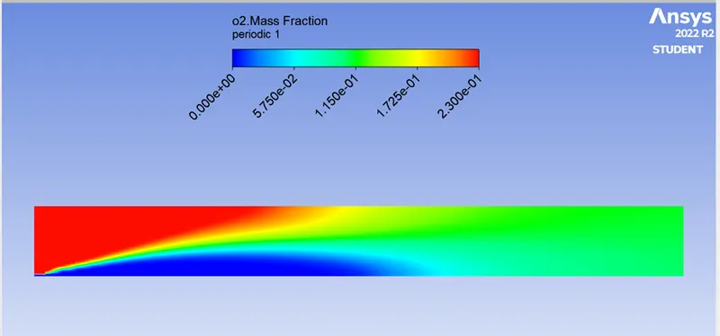
Mass Fraction of O2:
CASE 3:
Adding 30% of Water to Fuel CH4:
Residual plot:
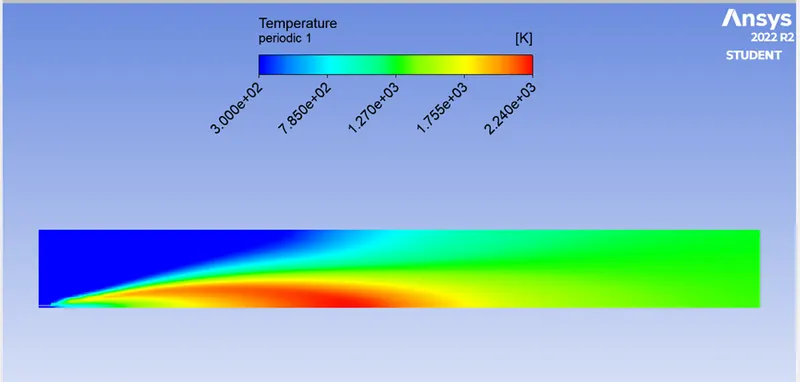
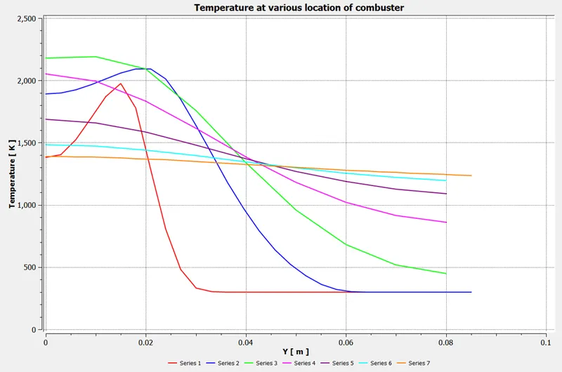
Temperature plot:
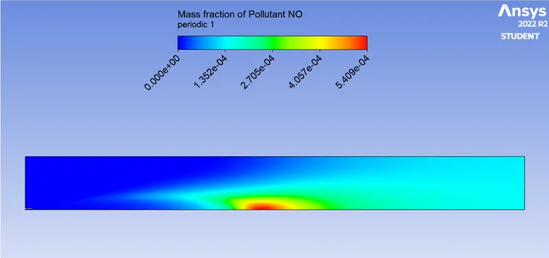
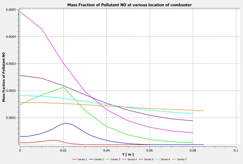
Mass Fraction of Pollutant NOx:
Mass Fraction of Soot:
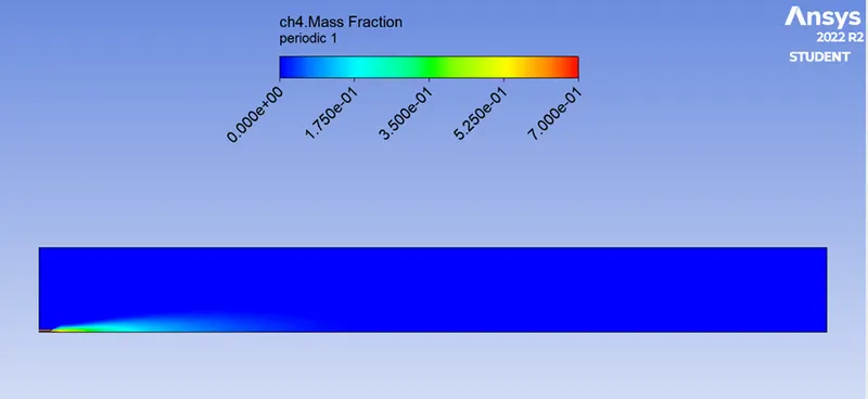
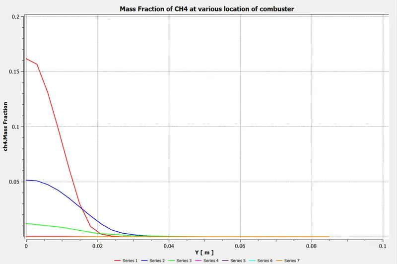
Mass Fraction of CH4:
Mass Fraction of CO2:
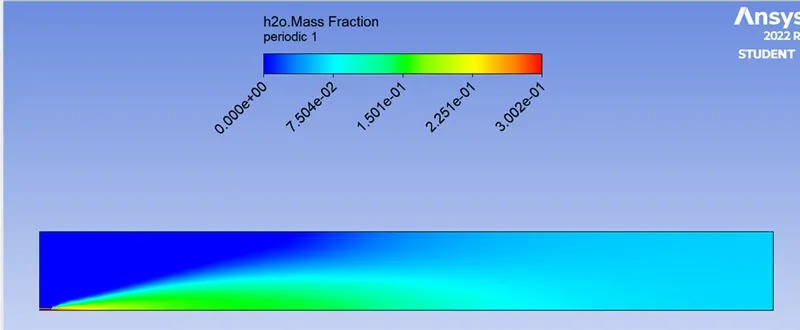
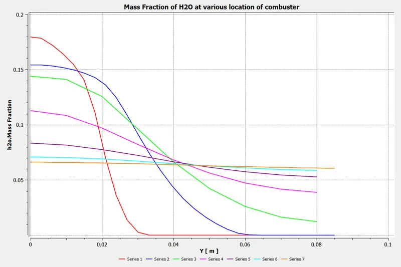
Mass Fraction of H2O:
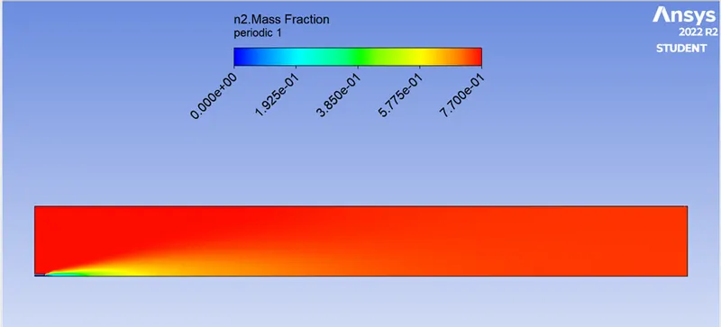
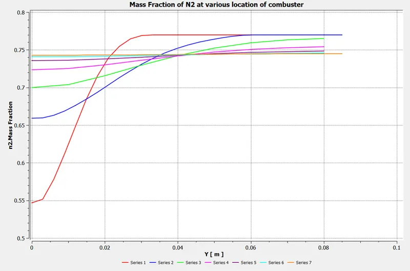
Mass Fraction of N2:
Mass Fraction of O2:
Observations and Results:
|
Addition of water In % |
Ratio of mixture of fuel and water |
Mass Fraction of NOx emission |
Mass Fraction of Soot Formation |
|
0 |
1 : 0 |
0.000655 |
1.947e-5 |
|
5 |
0.95 : 0.05 |
0.000476 |
3.681e-6 |
|
15 |
0.85 : 0.15 |
0.000305 |
5.208e-7 |
|
30 |
0.70 : 0.30 |
0.000137 |
2.420e-8 |
We can observe that as the mixing of water to fuel increases the emission of NOx decreases at outlet of combustor.
As the increases of water addition to fuel the Soot formation also decreases as NOx emission.
By adding water to fuel the temperature decreases in the creation of heat into volumetric zone.
We can see that from the beginning, CH4 is burning from high at 1 to near 0. But in real there are some unburnt carbon particles always remains.
Conclusion:
To reduce the pollution that is generate in the methane air combustion reaction we add water and by adding the water content in the fuel we can see that the number of pollutants generated due to the reaction decreases.
By increasing the water content in fuel, the maximum temperature generated inside the combustor decreases.
NOx and soot are harmful to human health and should be minimized, it is advisable to have some water content of around 25-30% by mole fraction in the fuel so as to get the least number of pollutants.