Week 10 - Simulating Combustion of Natural Gas.
Aim- Thermal simulation of a lithium ion battery pack
Theory-
Lithiumion batteries -A lithium-ion battery is a rechargeable lithium battery that depends upon lithium ions flowing between negative and positive electrodes.During the charging phase, lithium ions flow from the positive electrode of the battery to the negative electrode. While in the case of discharging the flow of ions is reversed.The movement of these ions creates a potential difference (voltage). Hence, when the device is connected to the battery the electrons pass to it and power your device.
Understanding Battery Terminology-
Before modelling a battery we must study the various parameters used to characterise the cells or batteries and the behaviour of the cell or battery with various operating conditions.
C-rates – In describing batteries, discharge current is often expressed as a C-rate in order to normalize against battery capacity, which is often very different between batteries. A C-rate is a measure of the rate at which a battery is discharged relative to its maximum capacity. A 1C rate means that the discharge current will discharge the entire battery in 1 hour. For a battery with a capacity of 100 Amp-hrs, this equates to a discharge
current of 100 Amps. A 5C rate for this battery would be 500 Amps, and a C/2 rate would be 50 Amps. Similarly, an E-rate describes the discharge power. A 1E rate is the discharge power to discharge the entire battery in 1 hour.
State of Charge (SOC) – An expression of the present battery capacity as a percentage of maximum capacity. SOC is generally calculated using current integration to determine the change in battery capacity over time.
Depth of Discharge (DOD) – The percentage of battery capacity that has been discharged expressed as a percentage of maximum capacity. A discharge to at least 80 % DOD is referred to as a deep discharge.
Terminal Voltage (V) – The voltage between the battery terminals with a load applied. The terminal voltage varies with SOC and discharge/charge current.
Open-circuit voltage (V) – The voltage between the battery terminals with no load applied. The open-circuit voltage depends on the battery state of charge, increasing with state of charge.
Internal Resistance –The resistance offered by the electrolyte inside the cell to the flow of electric current through it is called the internal resistance of the cell.c3 = capacty
The importance of a cooling system
While advancements have been made in electric vehicle batteries that allow them to deliver more power and require less frequent charges, one of the biggest challenges that remain for battery safety is the ability to design an effective cooling system.
IN ELECTRIC CARS, DISCHARGING THE BATTERY GENERATES HEAT; THE MORE RAPIDLY YOU DISCHARGE A BATTERY, THE MORE HEAT IT GENERATES.
Batteries work based on the principle of a voltage differential, and at high temperatures, the electrons inside become excited which decreases the difference in voltage between the two sides of the battery. Because batteries are only manufactured to work between certain temperature extremes, they will stop working if there is no cooling system to keep it in a working range. Cooling systems need to be able to keep the battery pack in the temperature range of about 20-40 degrees Celsius, as well as keep the temperature difference within the battery pack to a minimum (no more than 5 degrees Celsius).
IF THERE IS A LARGE INTERNAL TEMPERATURE DIFFERENCE, IT CAN LEAD TO DIFFERENT CHARGE AND DISCHARGE RATES FOR EACH CELL AND DETERIORATE THE BATTERY PACK PERFORMANCE.
Potential thermal stability issues, such as capacity degradation, thermal runaway, and fire explosion, could occur if the battery overheats or if there is non-uniform temperature distribution in the battery pack. In the face of life-threatening safety issues, innovation is continually happening in the electric vehicle industry to improve the battery cooling system.
Battery Thermal Management System (BTMS)
- The electric vehicle has a battery management system (BMS) to provide essential information such as:
- Thermal Protection
- Over and Under voltage protection
- Over-current Protection
- Prolong battery life
- Cell Balancing
- SoC and SoH calculation
- Communication with all battery components
- Data acquisition and analysis
- The high battery temperature leads to poor performance, short lifetime, and risk of blasting. Therefore, a BTMS is essential for all battery modules.
- The main purpose of a BTMS is to maintain the battery system in the optimum temperature range and keep uniform temperature variation in the battery modules
- Other factors for battery selection are weight, size, reliability, and the cost
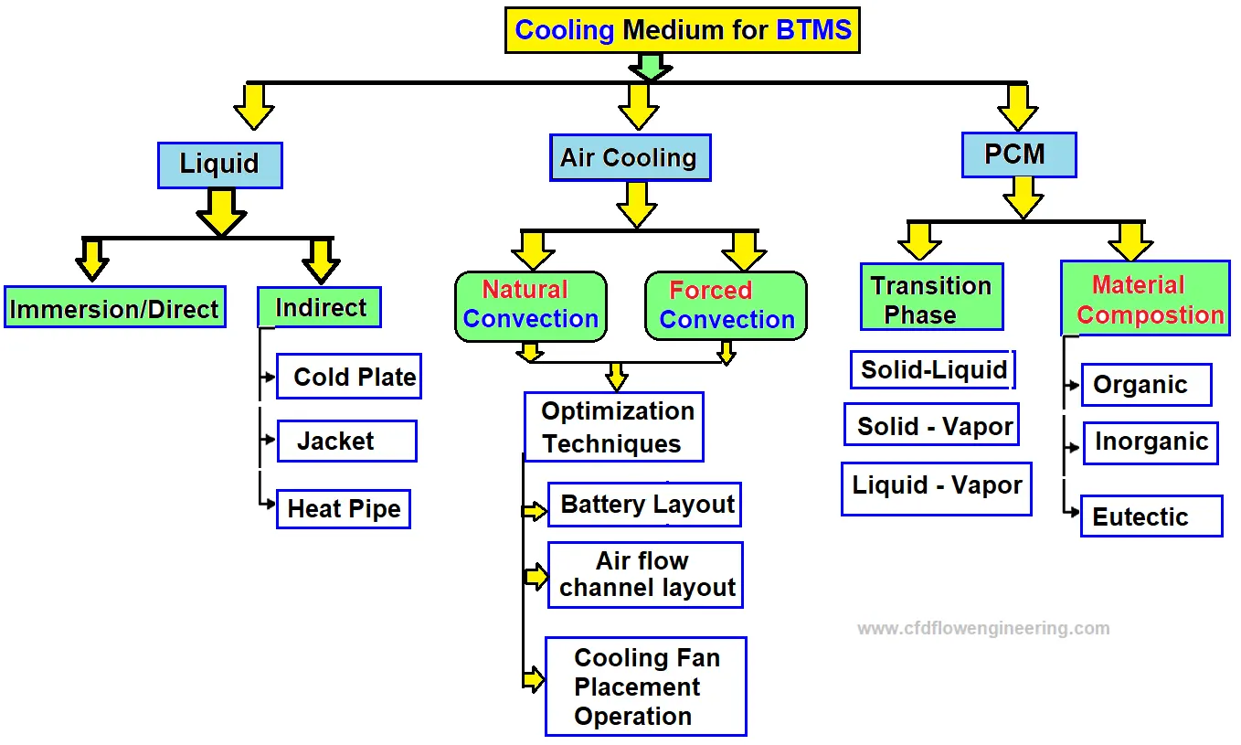
- The following figure shows the most used thermal management techniques for battery module
Procedure-
Geometry-
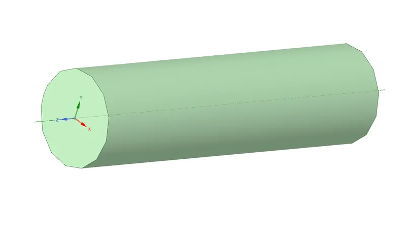
First open up space claim thandraw a circle fo dia 18 mm in the sketch mode and using the pull command extrude it out to length of 65mm now we have one cell ready
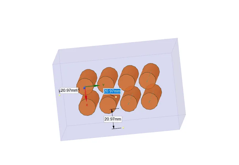
now using linear pattern tool we can make a 4x2 cell pack use the spacing between cell acq to case

use the enclosure tool to create enclosure around the cell pack
Meshing-
first name the faces acq inlet, outlet , fluid and cells
using element size 5mm
and body sizing method on cell 2mm
we have no of elements as 488250

Setups-
K W SST MODEL
enable energy
gravity =9.81m/s
set up material create lithium
lithium-
density = 2272 kg/m3
specific heat = 1200j/kgk
in cell zone conditions apply materials lithium to cells and air to fluid vol
give lithium a source ter (constant)
heat source = 48750 W/mK
Give the inlet velocity and set it up as input parameter

create a report for heat transfer coeff anf temp at cells and give them as output parameter
use hybrid initialiation and run for 200 iterations
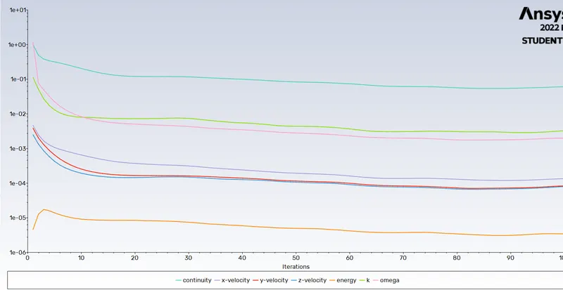
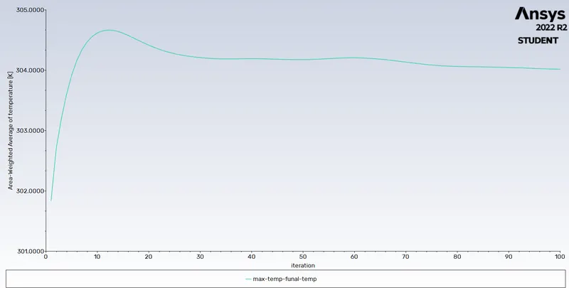
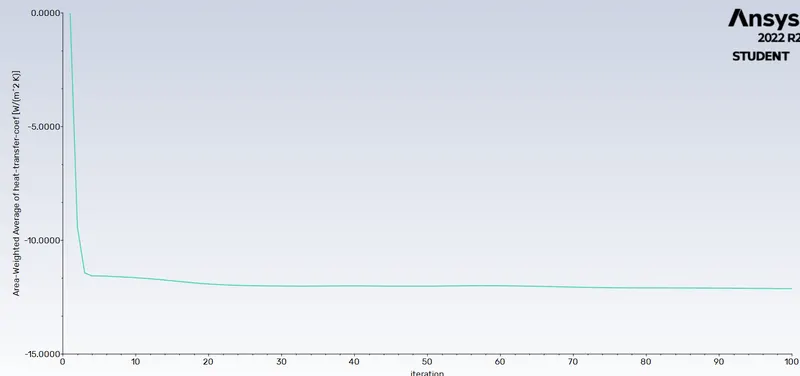
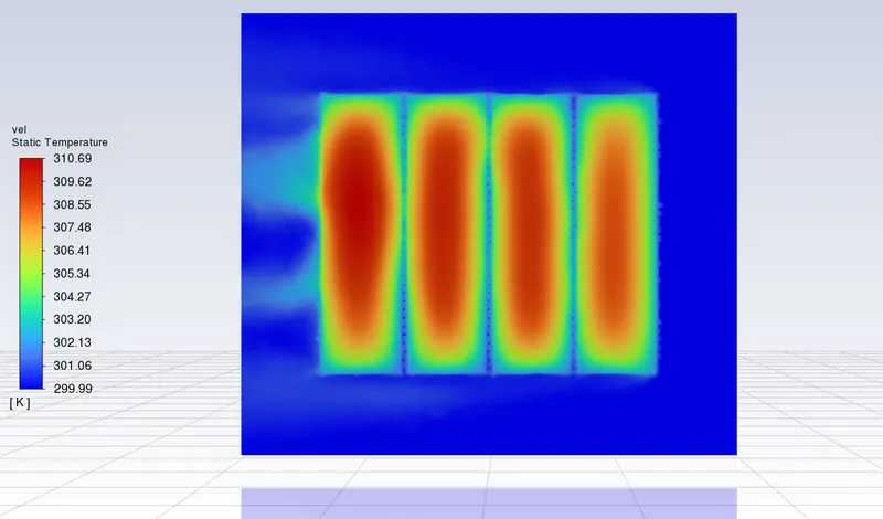
Case 1
vel = 3m/s 2mm gap
residue plot-
Temp plot-
heat transfer coeff-
temp contour-
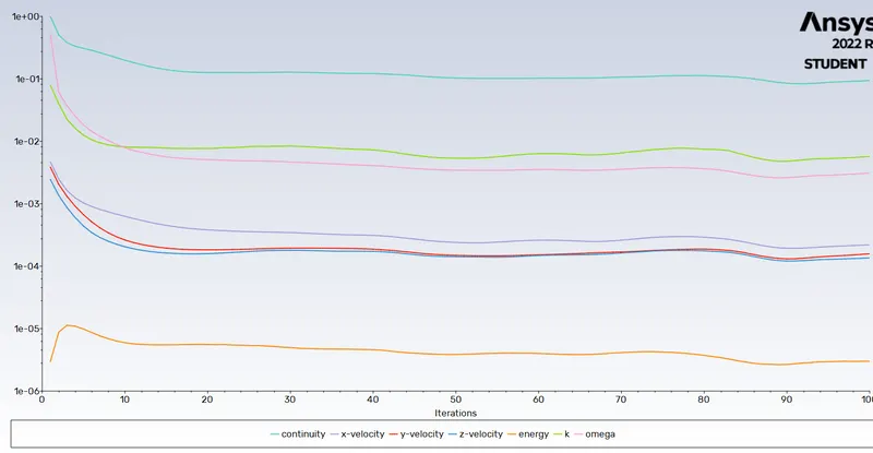
case 2 2mm gap Velocity = 5m/s
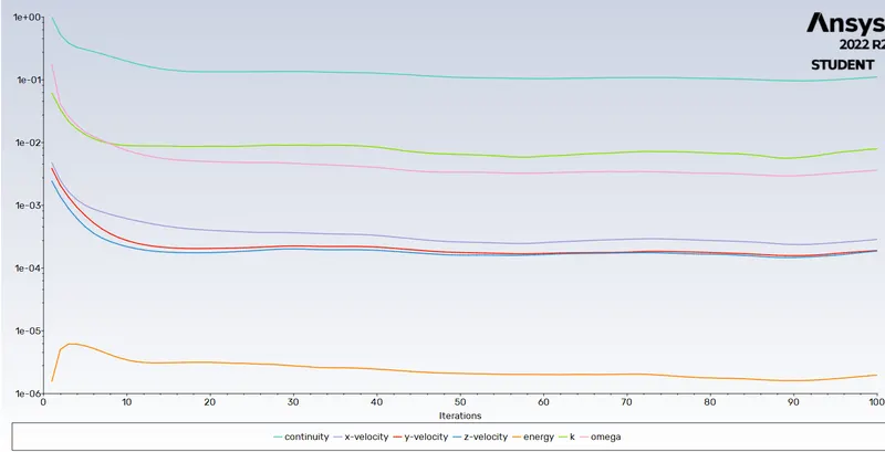
residue plot-
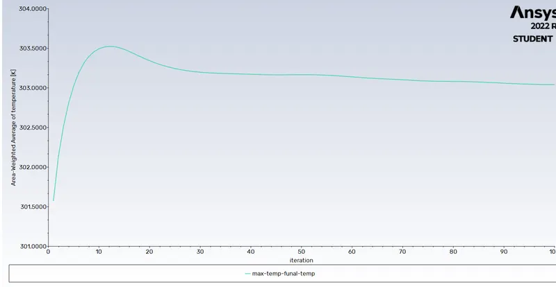
Temp plot-
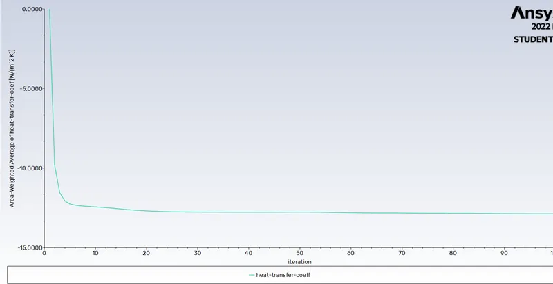
heat transfer coeff plot-
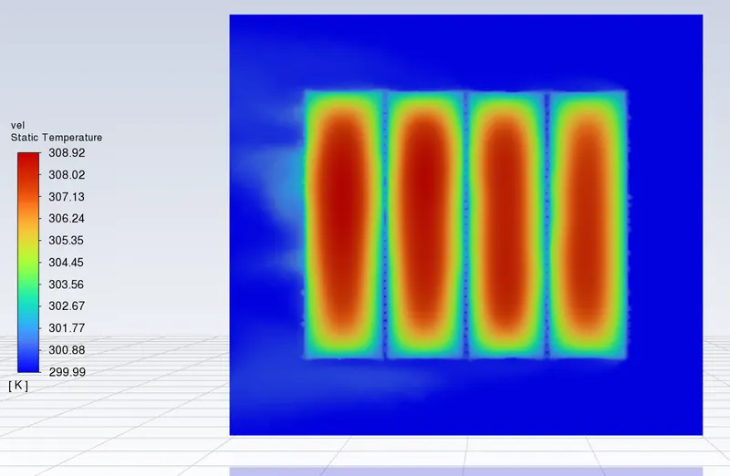
temp contour-
Case 3- 2mm gap and 10m/s vel-
residue plot-
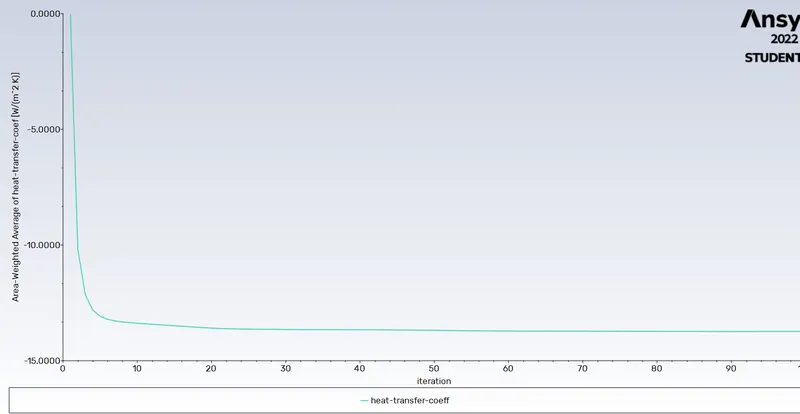
heat transfer coeff=
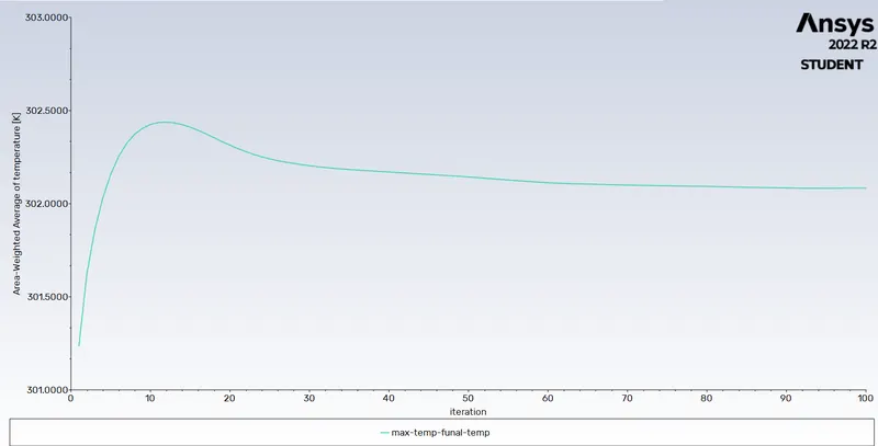
temp plot-
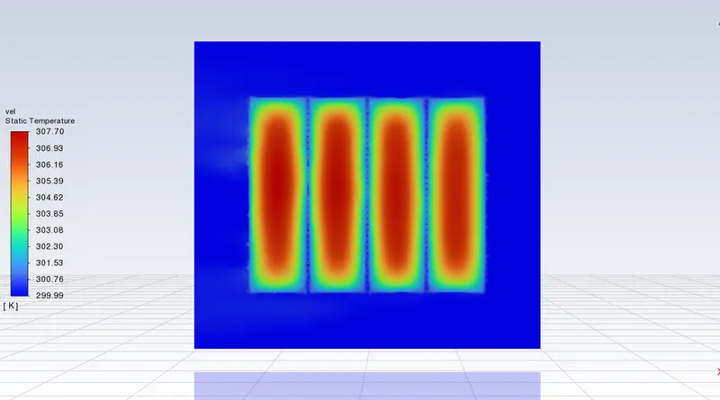
Temp contour-
Case 4 4mm gap velocity = 10m/s
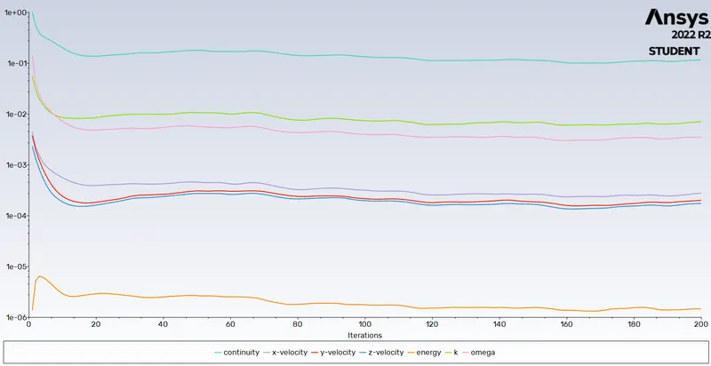
residual plot-
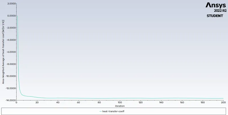
heat transfer coeff plot-
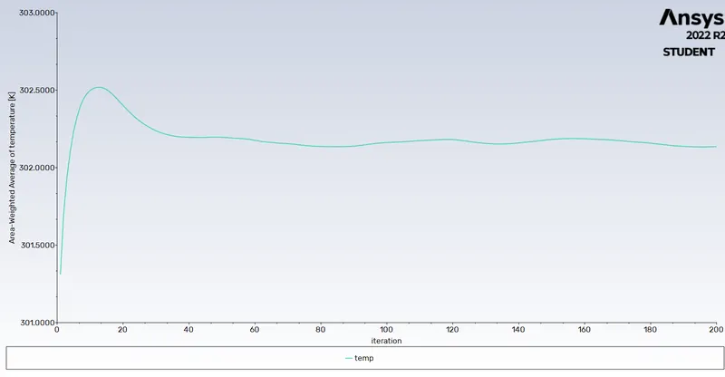
Temp plot-
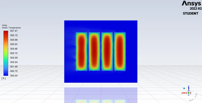
Temp contour-
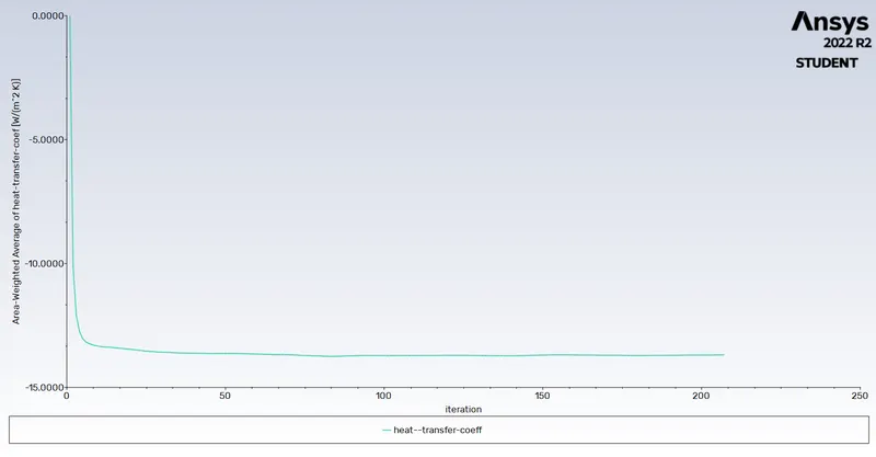
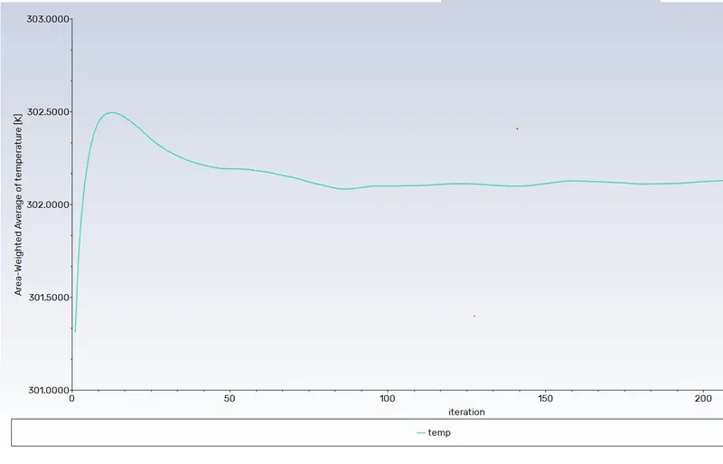
Case 5 6mm gap vel 10m/s
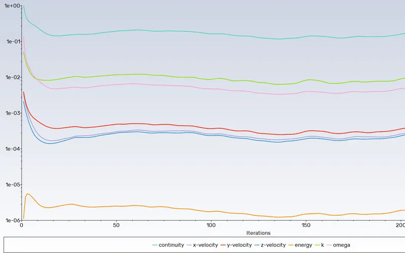
residual plot-
heat transfer coeff-
Temp plot-
Final Data-
| sn no | Gap between cells (mm) | velocity (m/s) | Temp of cell (Kelvin) | heat transfer coeff (W/m2K) |
| 1 | 2 | 3 | 304.23 | -13.73 |
| 2 | 2 | 5 | 303.37 | -13.43 |
| 3 | 2 | 10 | 302.25 | -13.15 |
| 4 | 4 | 10 | 302.23 | -13.82 |
| 5 | 6 | 10 | 302.18 | -13.96 |
Conclusion-
As we can see from the above results increasing the velocity certainly helps to cool the cool down cell to almost 2K the heat transfer coeff is is not much affected increasing the gap is also a good measure to keep cells from heating up
Transient solution-
transient solver
time step size 0.02
no.of time steps- 200
case 6mm gap and vel = 10m/s
vel and animation-
https://drive.google.com/file/d/1OsSc7CV7ZJ3ISVgiVq6g7onU_iq2l5vD/view?usp=sharing
temp animation-
https://drive.google.com/file/d/17sStE5wSMR6ajjGPuVRHXh-6hKdM0cKJ/view?usp=sharing