Week 10 - Simulating Combustion of Natural Gas.
CHALLENGE REPORT :
AIM :
To perform the heat transfer analysis for the cylindrical lithium ion battery with heat generation boundary condition using the Ansys software.
OBJECTIVE :
* Create the battery back system (4*2) and air as the working fluid for cooling the battery back.
* To perform mesh independent study.
* Run the simulation by varying velocity of air as 3, 5, 10m/sec and also vary the space between batteries as 2, 4, 6mm and discuss the results.
* Find the maximum temperature, average temperature and surface heat transfer coefficient obtained by the batteries.
* Create the temperature, velocity contours and the velocity vectors and the animation for the solutions.
INTRODUCTION :
BATTERY COOLING SYSTEM
Probably the most common battery cooling system used in electrified vehicles as the system can use water-glycol as the cooling fluid. The cells are immersed in a dielectric and the dielectric then flows through a heat exchanger to extract the heat.
EV Battery Cooling systems typically feature a liquid cooling loop specifically designed to be the most efficient method of heat transfer in the smallest, lightest form factor possible. Added weight decreases EV battery range. Smaller EV battery cooling systems enable more room for other systems or less material and vehicle weight.
Electric vehicle battery cooling plates mounted on battery modules bring cooled liquid near the module. The working fluid absorbs heat conducted into the cold plate from the module as it passes through. Heat is carried in the pumped liquid away from the battery pack for dissipation with a heat exchanger or radiator.
Battery Thermal Management System (BTMS)
- The electric vehicle has a battery management system (BMS) to provide essential information such as:
- Thermal Protection
- Over and Under voltage protection
- Over-current Protection
- Prolong battery life
- Cell Balancing
- SoC and SoH calculation
- Communication with all battery components
- Data acquisition and analysis
- The high battery temperature leads to poor performance, short lifetime, and risk of blasting. Therefore, a BTMS is essential for all battery modules.
- The main purpose of a BTMS is to maintain the battery system in the optimum temperature range and keep uniform temperature variation in the battery modules
- Other factors for battery selection are weight, size, reliability, and the cost
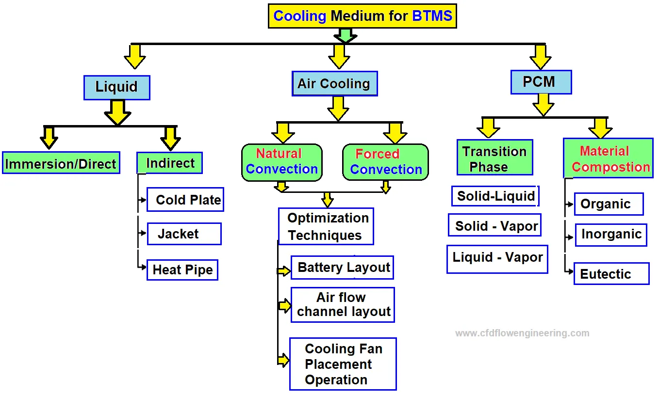
- The following figure shows the most used thermal management techniques for battery module.
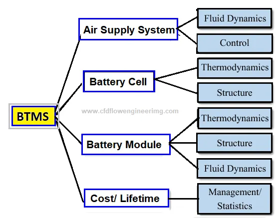
Different Battery Cooling Methods Used in BTMS
- To adapt to EVs, BTMS must ensure features such as high performance, simplicity, low weight, reduced cost, low use of parasitic power and fast packaging, and easy maintenance
- Two types of battery cooling systems (BCS) are common which are external or internal. Many researchers and industries have been developing BCSs
- External Battery cooling systems (EBCS) are classified into several different ways
- Battery cooling can be categorized based on the method or technique.
- Liquid or gas cooling: plate type or use of mini-channel)
- Heat pipe
- Phase Change Material (PCM)
The Need for Battery Cooling Systems in Electric Vehicles
Overheating is one of the major causes that accelerates the rate of battery degradation in electric vehicles. Heat generation makes the battery work hard and causes its performance to deteriorate over time. The direct current fast charging and rapid charging of the battery are not good for battery health, as the accelerated electric currents create higher temperatures.
The high temperature in the battery causes battery fluid evaporation and damage to the internal structure of the battery, which cannot be corrected. At optimal temperatures, discharge power availability, charge acceptance during regenerative braking, and battery health are at their best. The battery life, electric vehicle driveability, and fuel economy degrade as the temperature increases. Considering the overall thermal effect on the battery, a battery cooling system is of great importance in electric vehicles.
Liquid Battery Cooling Systems in Electric Vehicles
The battery cooling system in electric vehicles regulates the temperature of the battery pack. The battery thermal management in electric vehicles uses cooling loops that contain liquid coolants such as ethylene glycol. An electric pump circulates the coolant through the batteries. Radiators are included in the cooling loop to release the heat to the ambient. The battery cooling system in electric vehicles can be either passive liquid cooling or active liquid cooling.
Passive Liquid Cooling Systems
In a passive liquid cooling system, the cooling power depends on the temperature difference between the ambient air and battery. The cooling performance can be improved by connecting fans behind radiators.
Active Liquid Cooling Systems
An active liquid cooling system is effective when the ambient temperature is higher than the battery temperature or when the temperature difference is too small. The active liquid cooling system consists of two loops. The primary loop is similar to the passive liquid cooling system. The secondary loop is in the air conditioning loop. It consists of two heat exchangers that work as evaporators and condensers, respectively. A quick response from the battery cooling system in electric vehicles is essential for reliable electric drive mobility.
HEAT TRANSFER COEFFICIENT :
The heat transfer coefficient is the proportionality constant between the heat flux and the thermodynamic driving force for the flow of heat (i.e., the temperature differance, ΔT ). It is used in calculating the heat transfer, typically by convection or phase transition between a fluid and a solid. The heat transfer coefficient has SI unit in watts per square meter kelvin (W/m2/K).
The general definition of the heat transfer coefficient is:
h=q/ΔT
PROCEDURE :
GEOMENTRY SETUP :
* Open the space claim and create a battery pack using the sketch mode.
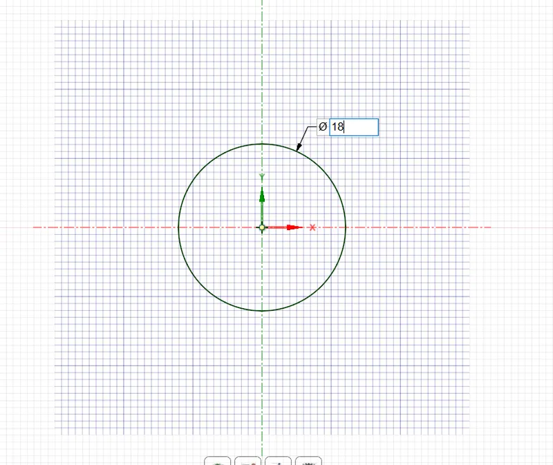
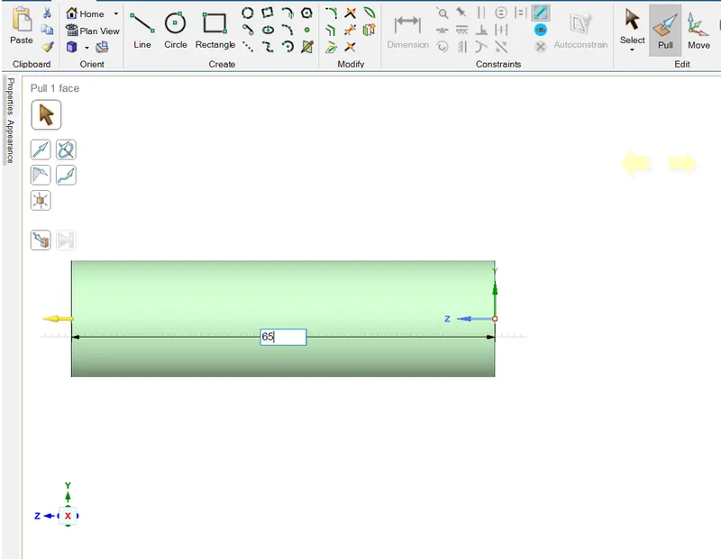
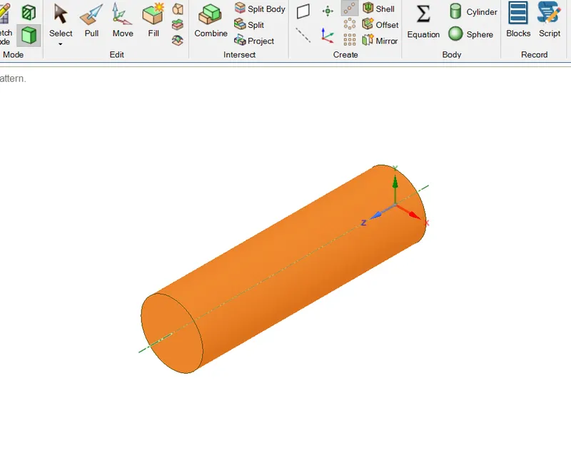
* Draw a circle with 18mm diameter and extrude it at height of 65mm using the pull option or move to 3d option .
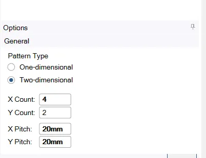
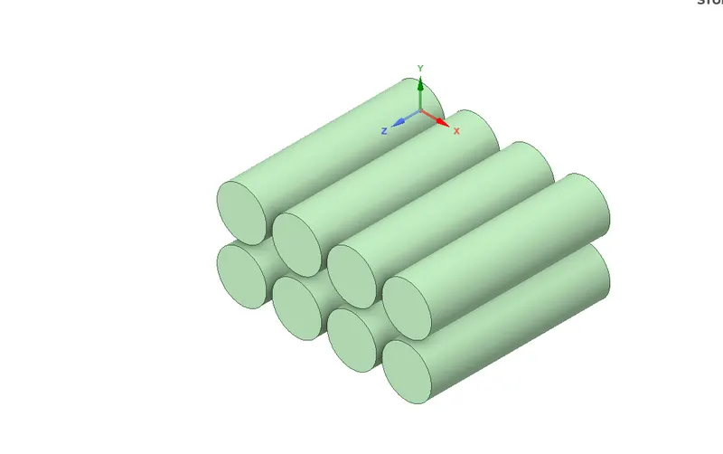
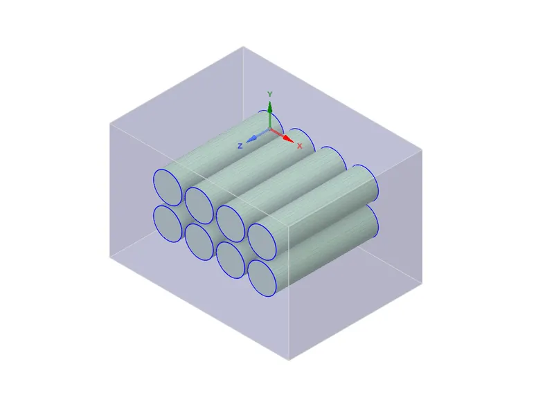
* Using the linear pattern in the design tab ( change to 3d, set 4*2 and distance between is 20mm, 20mm ), create the battery pack with 8 batteries (4*2).
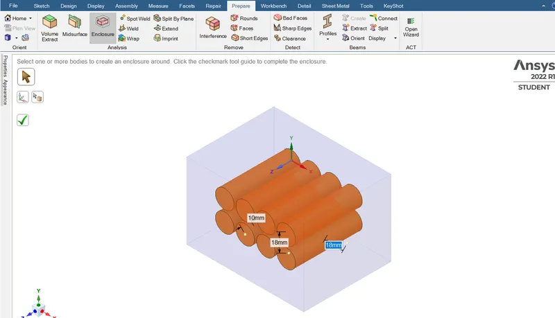
* Create an box enclouser with lenght*breath*height as 65*65*10 by the help of enclouser option in the prepair tab.
space claim ----> Design ----> sketch mode ( select the plane ) ----> create circle ----> extrude it using pull with height as 65 ---->
design tab ----> linear pattern (pattern it into 4*2 as 8 battery ) ----> Prepair tab ----> Create box enclouser
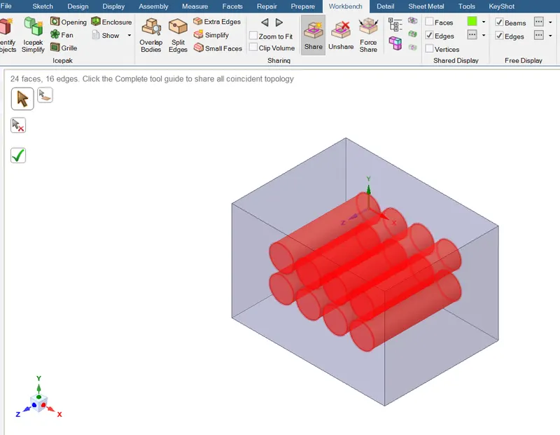
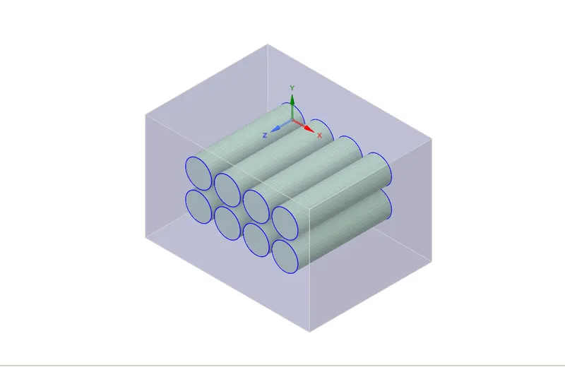
* The given model is ready with the all geomentry and also with enclosers. So we need do the share tropology which is used to carry the information from nodes of one model to other models. It will coincides the nodes of one model to other model. Here to get the share tropology disable the preserve instance.
space claim -----> workbench -----> share tropology (disable the preserve instance )
SINGLE BATTERY :
 |
 |
BATTERY PACK :
 |
 |
ENCLOUSER :
SHARE TROPOLOGY :
MESH :
* After completing the geomentry open the mesh modul to mesh the model.
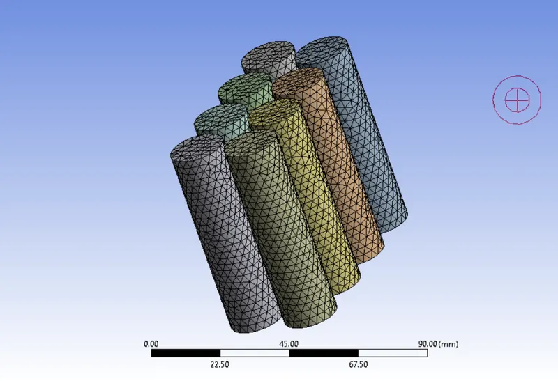
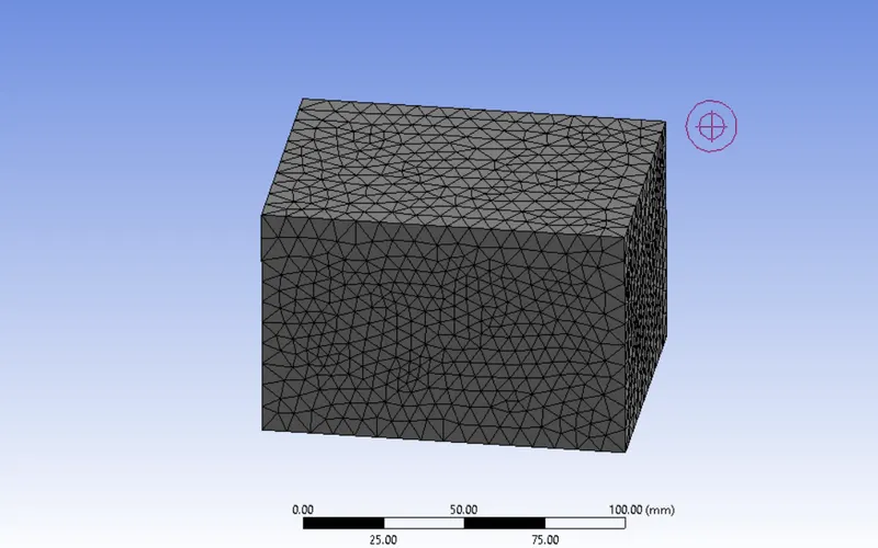
* Generate the mesh to the given model with element size as 8mm and do the name selection as inlet , outlet, conversion wall, battery, fluid, battery walls.
* Insert the sizing for the battery wall with element size as 3mm and enable the capture curvature so that it capyure at the curve area.
mesh -----> generative mesh -----> element size
mesh -----> insert -----> Face sizing or method -----> elemnt size -----> capture curve (yes)
* Enable the Inflamation layer at battery wall and just update it.
* Here we are going to perform the grid independent study. so taken two cases for it.
| CASES | ELEMENT SIZE | FACE SIZING | NO OF ELEMENTS |
| 1 | 8mm | 3mm | 201950 |
| 2 | 3mm | 2mm | 463507 |
SETUP SOLUTION :
* After the mesh open the set up modul and here we have to set the condition like physics, boundery conditions, type of analysics, Solution setups and the requried outups.
* Here enable the steady state solver because we considering only the final results or condition not considering the changes in every time (sec). Pressure based is used because the velocity of air low ( less than 0.3 of mach number ) .
* Enable the energy because we wants maximum temperature and heat transfer coefficient which is the part of energy transfer.
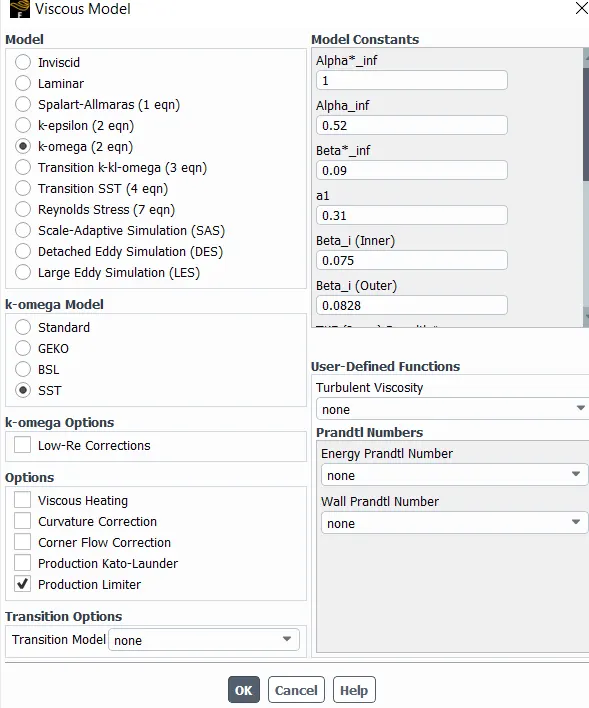
* Select the default K-omega ,SST turbulent model which is much useful to capture the change near the body.
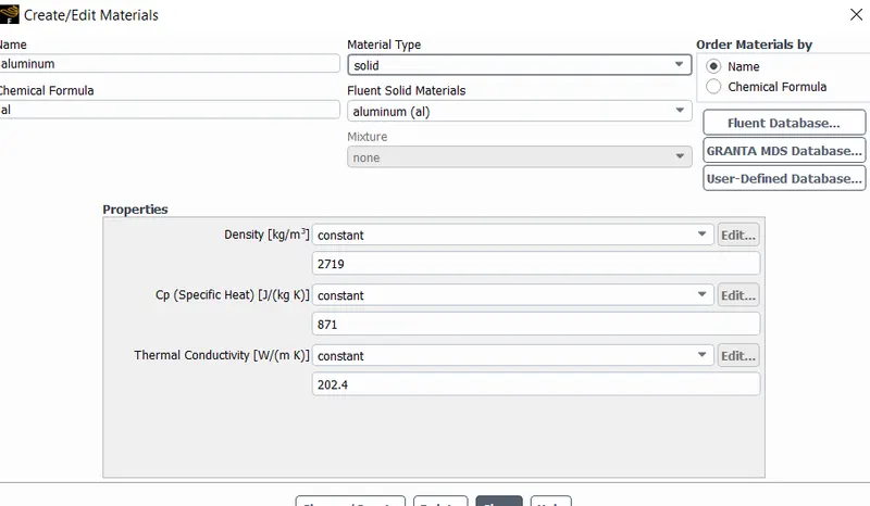
* For the material selection some of the materials are assumed based on the reseach papers. To create materials go to material database and choose the material. if the material is not available select any material and change the properties of its.
* Create the new material as lithium from the fluid database in the material selection by changing the property of aluminum.
Physics ---> Materials ---> Fluid Data base ---> select the aluminum ---> copy ----> Change the property of aluminum ---->
Add property of lithium
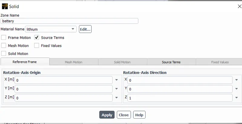
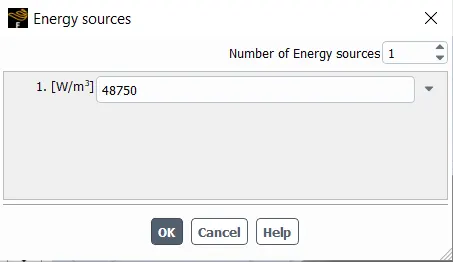
* Assign the created material to the respective parts in the cell zone option and when assigning for battery wall we wants to give the sorce term as 1 and constant and give heat generated is 15625000 W/mm^3 by assuming the heat decipated as 1W.
* Assign the boundary conditions for the inlet, outlets . For the inlet velocity consider as three cases of velocity and temperature is default 300K and for the outlet is default pressure outlet.
The case of velocity inlet,
---->Case 1: Velocity = 3m/s
---->Case 2: Velocity = 5m/s
---->Case 3: Velocity = 10m/s
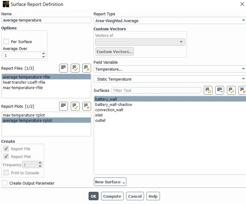
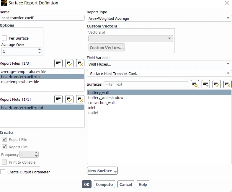
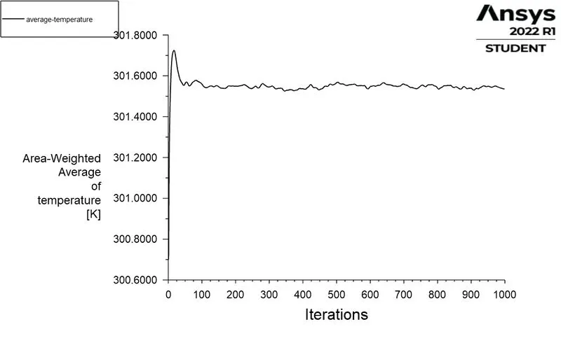
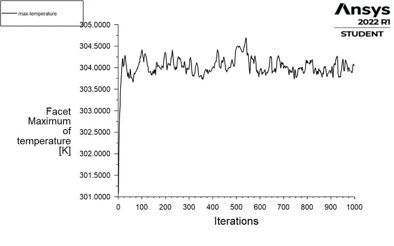
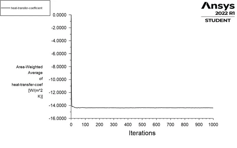
* Then set the solution report by using the definition. The three report is need for these challenge Maximum Temperature, Average Temperature, Heat Transfer Coefficient.
Average Temperature,
Definition ----> new ----> solution report ----> Area weighted average----> choose the temperatureand andbattery wallto air and enable print to console.
Average Temperature,
Definition ----> new ----> solution report ----> Facet max ----> choose the temperatureand and battery wall exposed to air and enable print to console.
Heat Transfer Coefficient,
Definition ----> new ----> solution report ----> Area weighted average ----> choose the wall flux and surface heat transfer coefficient and battery wall exposed to air and enable print to console.
* Select the initialize option to initialize it.
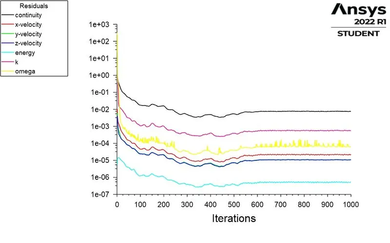
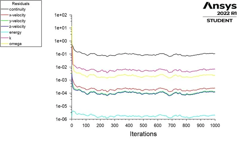
* Give 1000 iteration and if the solution is not converged and then increase the iteration and calculate it.
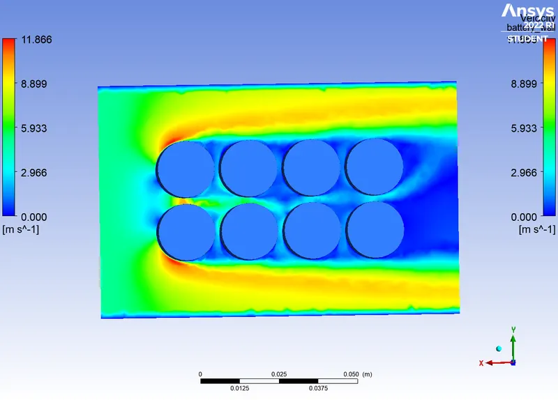
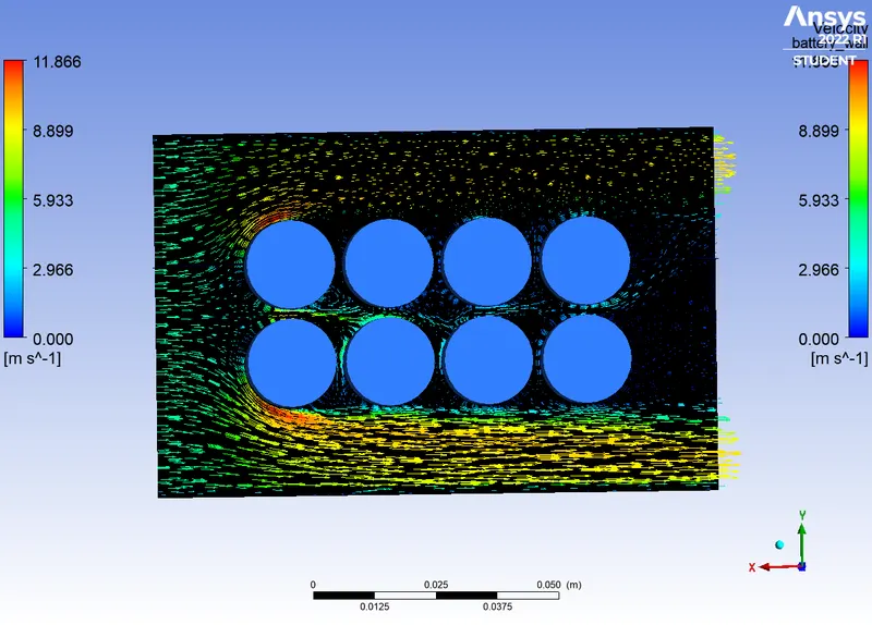
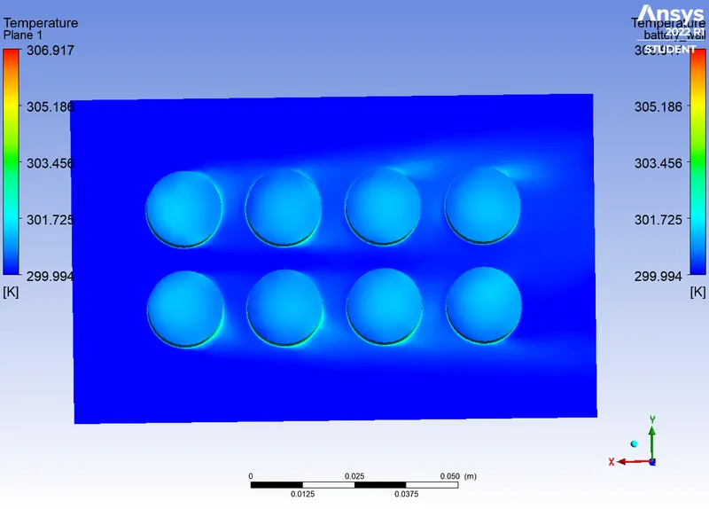
* Create the contours for Temperature, heat transfer coefficient and velocity in the created plane.
* In the result option we can create the plots for Temperature and velocity which is used to compare the results.
* Do these procedures for other two cases by changing the distance between the batteries by choosing the best case.
RESULT :
CASE 1 :
MESH :
ELEMENT SIZE : 8mm
FACE SIZING : 3mm
INLET VELOCITY : 3m/s
DISTANCE BETWEEN BATTERY : 2mm
|
RESIDUAL POLTS : |
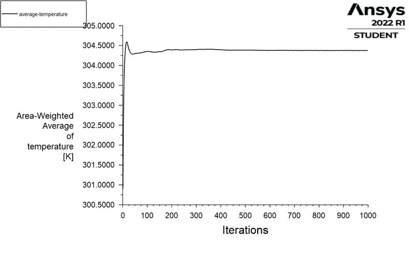
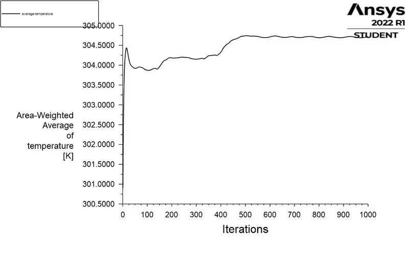
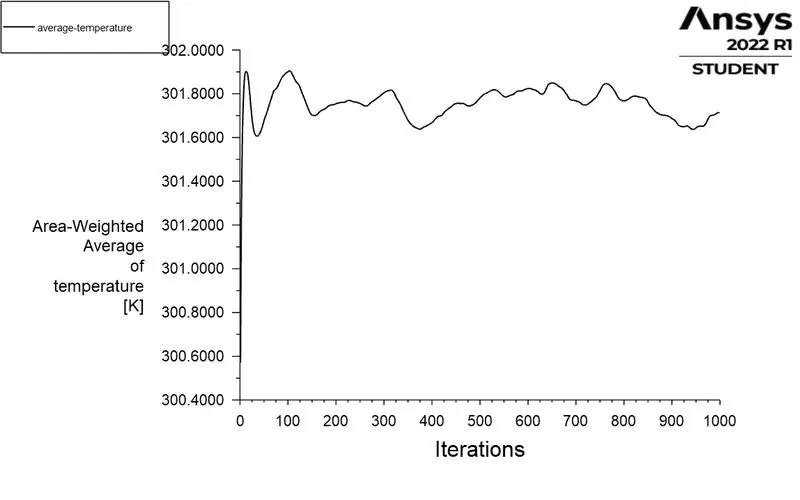
AVERAGE TEMPERATURE : |
|
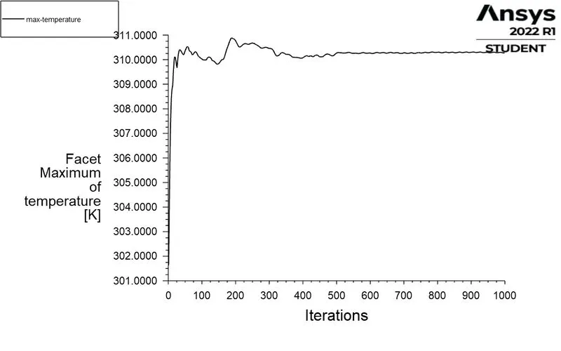
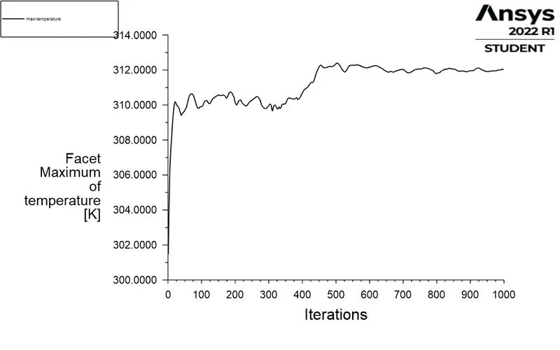
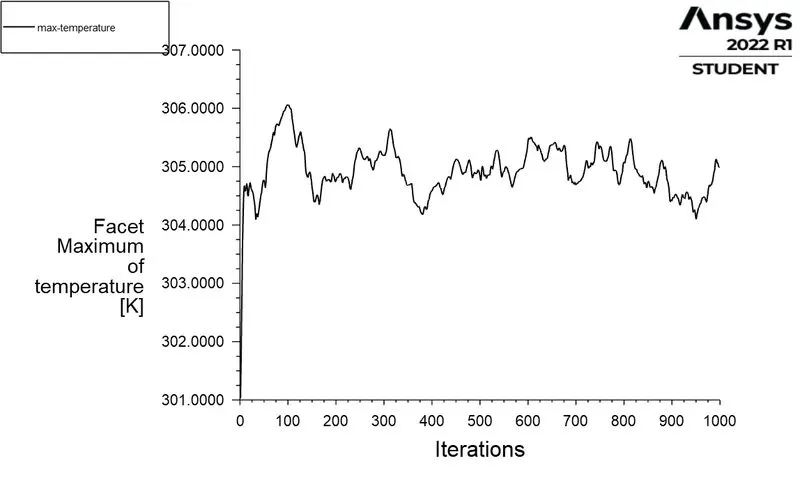
MAXIMUM TEMPERATURE : |
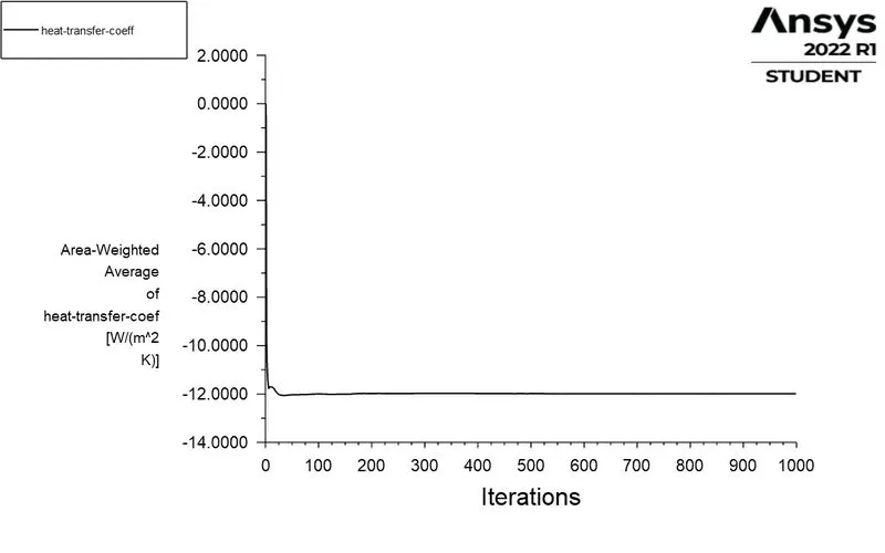
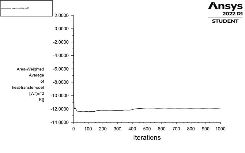
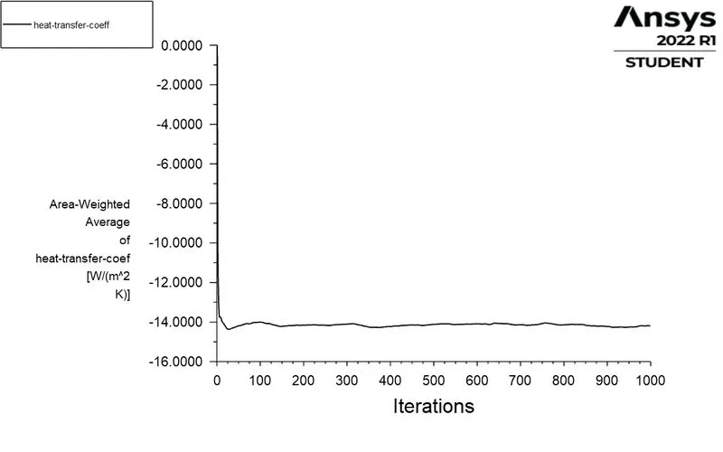
HEAT TRANSFER COEFFICIENT : |
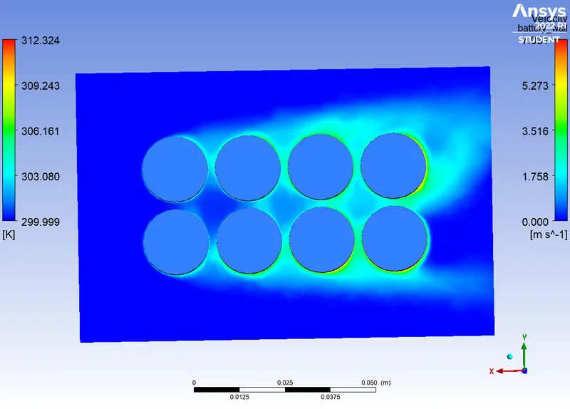
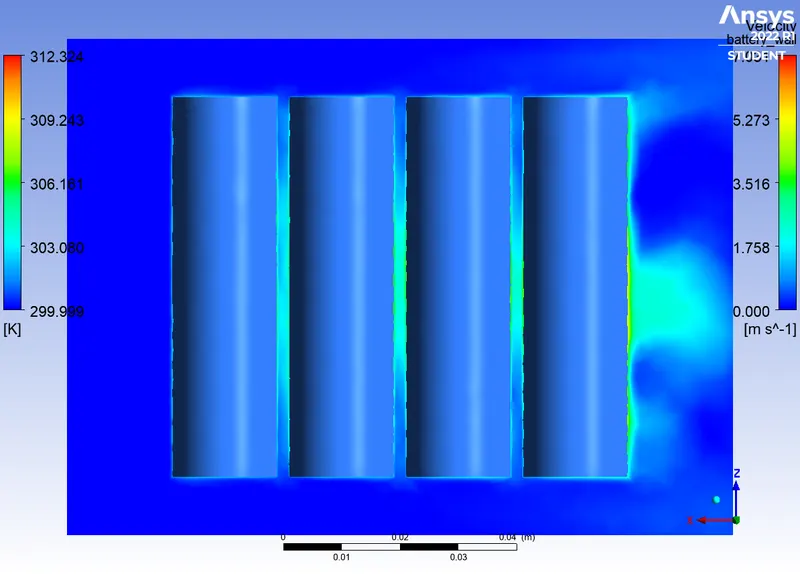
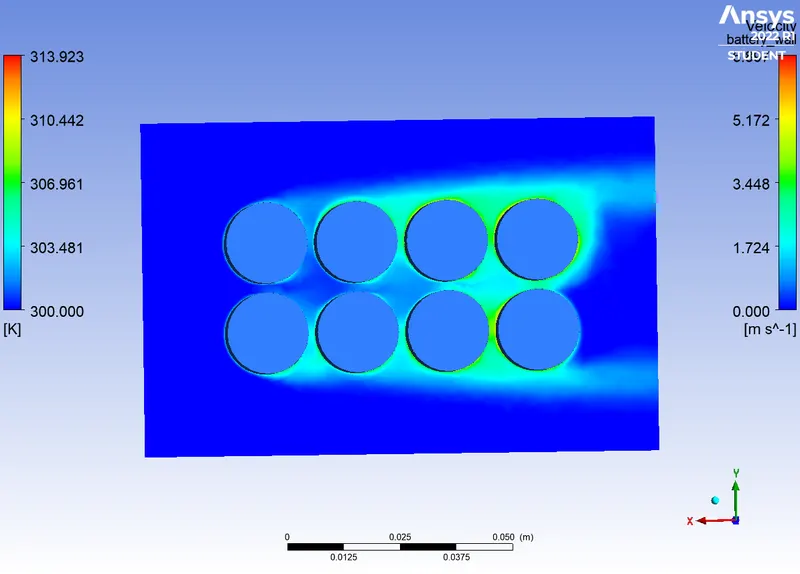
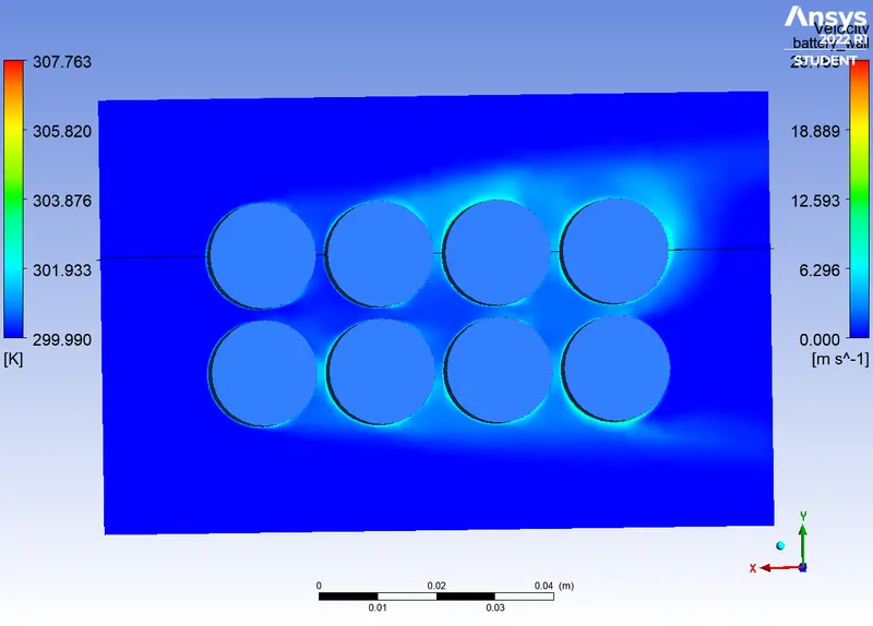
TEMPERATURE CONTOUR :
 |
 |
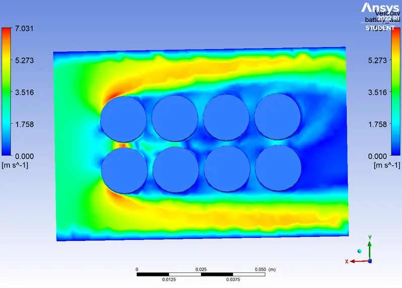
VELOCITY CONTOUR :
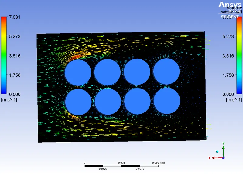
VELOCITY VECTOR :
CASE 2 :
MESH :
ELEMENT SIZE : 3mm
FACE SIZING : 2mm
INLET VELOCITY : 3m/s
DISTANCE BETWEEN BATTERY : 2mm
|
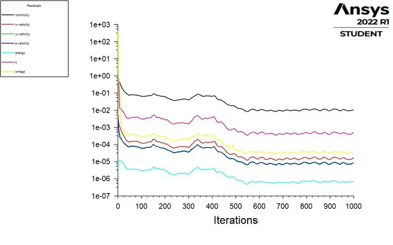
RESIDUAL POLTS : |
AVERAGE TEMPERATURE : |
|
MAXIMUM TEMPERATURE : |
HEAT TRANSFER COEFFICIENT : |
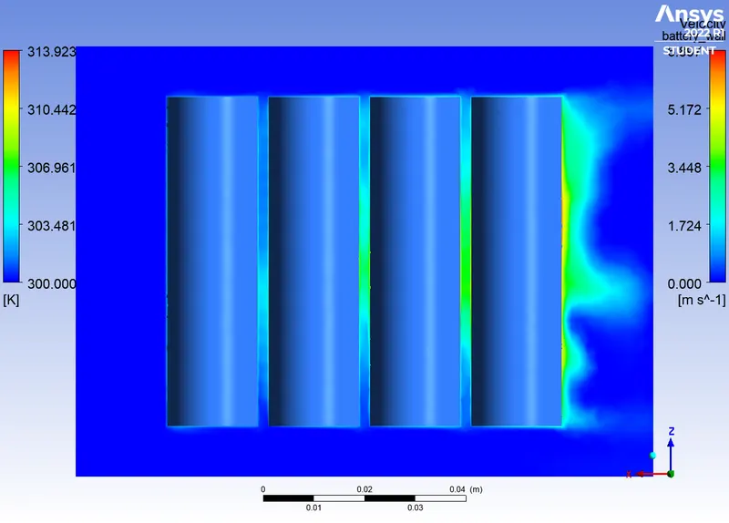
TEMPERATURE CONTOUR :
 |
 |
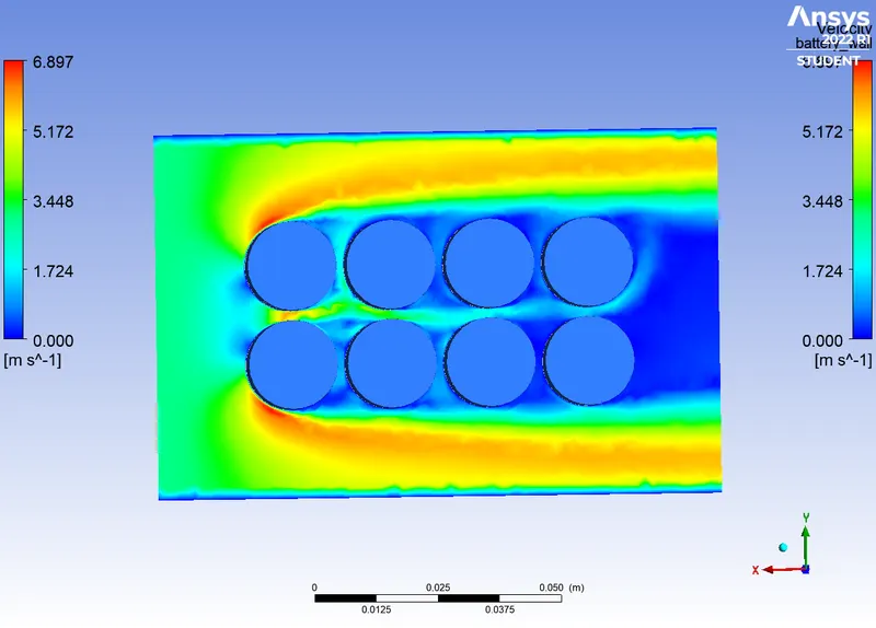
VELOCITY CONTOUR :
VELOCITY VECTOR :

CASE 3 :
MESH :
ELEMENT SIZE : 3mm
FACE SIZING : 2mm
INLET VELOCITY : 5m/s
DISTANCE BETWEEN BATTERY : 2mm
PLOTS :
|
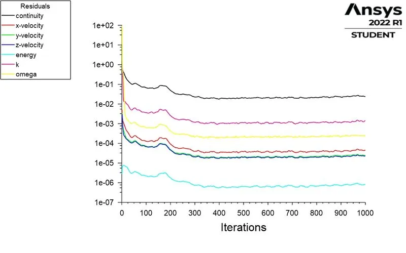
RESIDUAL POLTS : |
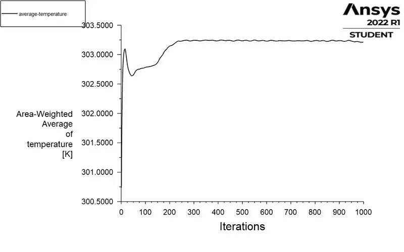
AVERAGE TEMPERATURE : |
|
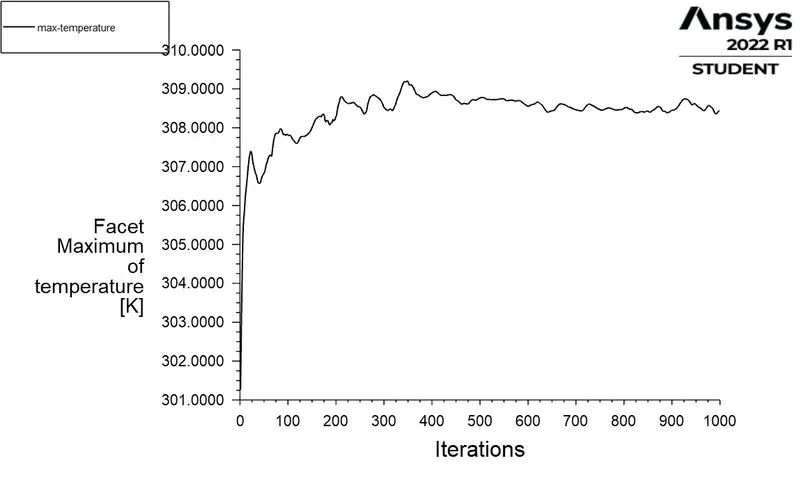
MAXIMUM TEMPERATURE : |
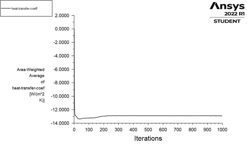
HEAT TRANSFER COEFFICIENT : |
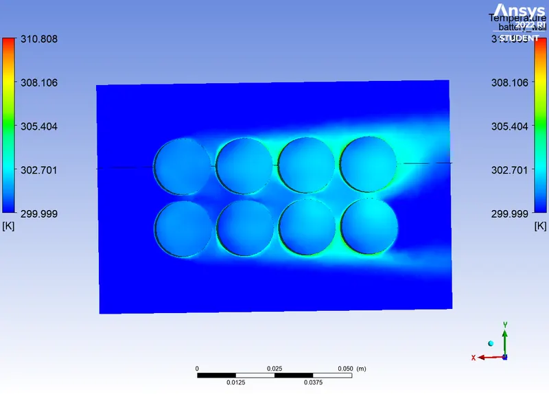
TEMPERATURE CONTOUR :
 |
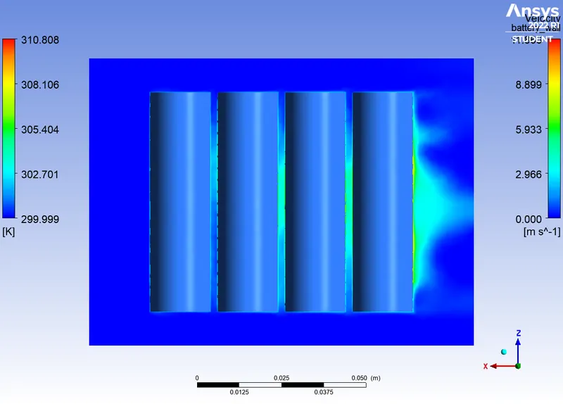 |
VELOCITY CONTOUR :
VELOCITY VECTOR :
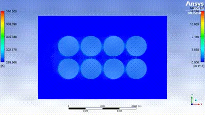
TEMPERATURE VIDEO :
CASE 4 :
MESH :
ELEMENT SIZE : 3mm
FACE SIZING : 2mm
INLET VELOCITY : 10m/s
DISTANCE BETWEEN BATTERY : 2mm
PLOTS :
|
RESIDUAL POLTS : |
AVERAGE TEMPERATURE : |
|
MAXIMUM TEMPERATURE : |
HEAT TRANSFER COEFFICIENT : |
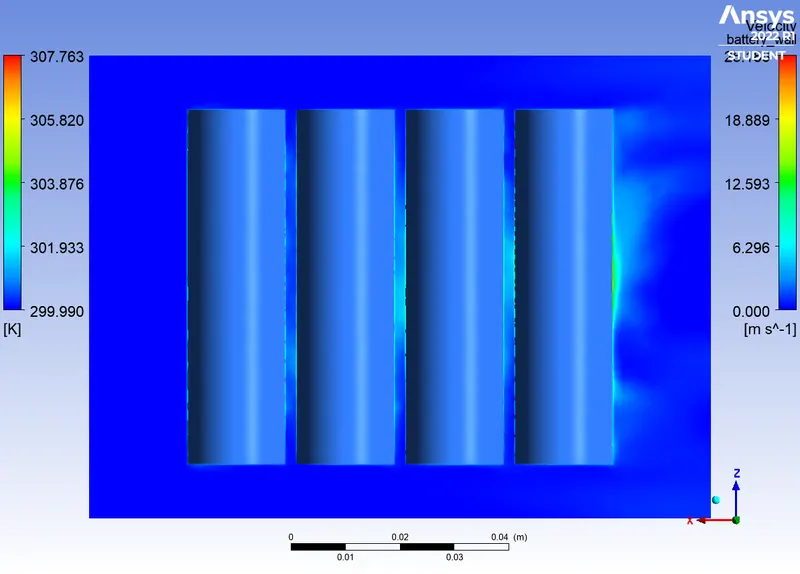
TEMPERATURE CONTOUR :
 |
 |
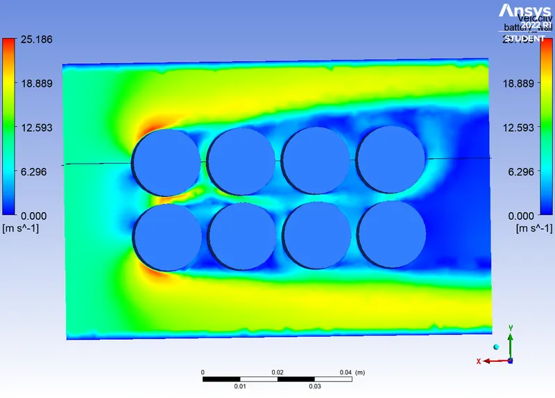
VELOCITY CONTOUR :
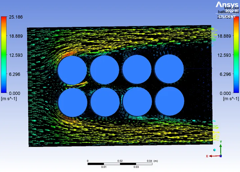
VELOCITY VECTOR :
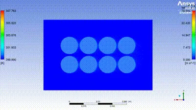
TEMPERATURE VIDEO :
CASE 5 :
MESH :
ELEMENT SIZE : 3mm
FACE SIZING : 2mm
INLET VELOCITY : 10m/s
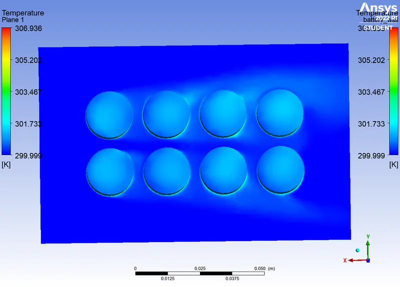
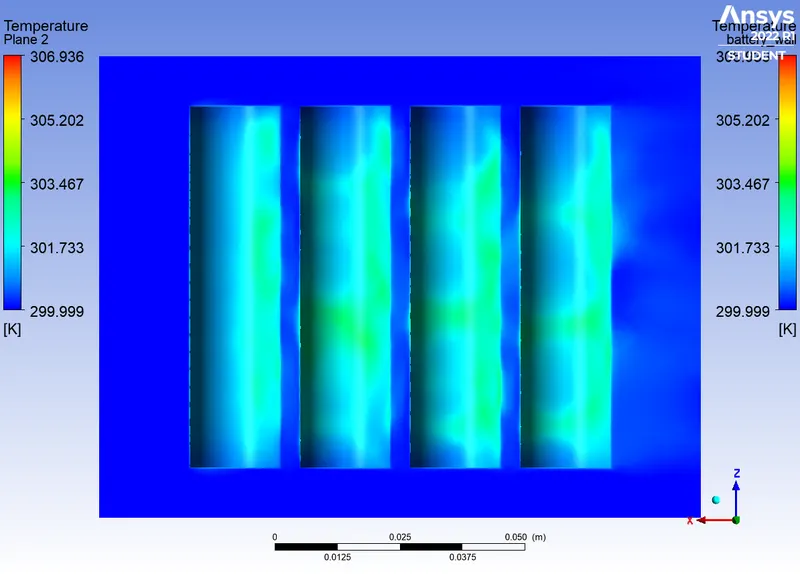
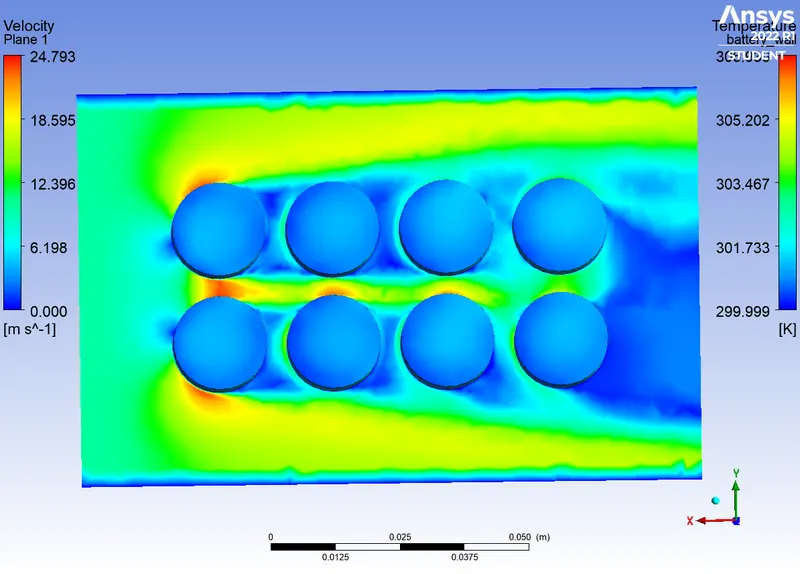
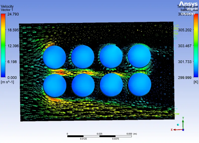
DISTANCE BETWEEN BATTERY : 4mm
PLOTS :
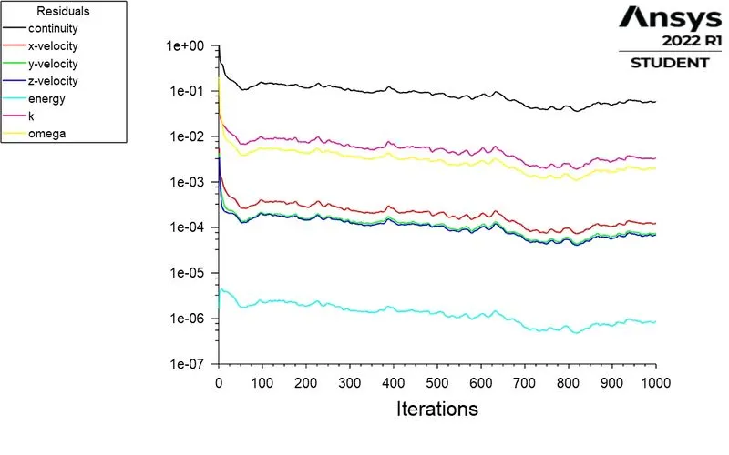
|
RESIDUAL POLTS : |
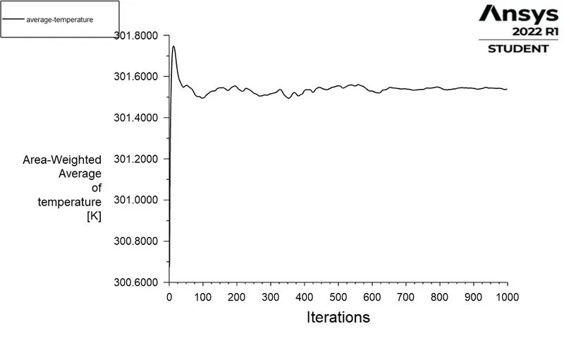
AVERAGE TEMPERATURE : |
|
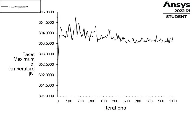
MAXIMUM TEMPERATURE : |
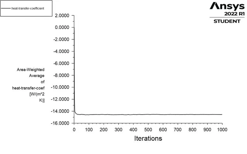
HEAT TRANSFER COEFFICIENT : |
TEMPERATURE CONTOUR :
 |
 |
VELOCITY CONTOUR :
VELOCITY VECTOR :
TEMPERATURE VIDEO :
CASE 6 :
MESH :
ELEMENT SIZE : 3mm
FACE SIZING : 2mm
INLET VELOCITY : 10m/s
DISTANCE BETWEEN BATTERY : 6mm
PLOTS :
|
RESIDUAL POLTS : |
AVERAGE TEMPERATURE : |
|
MAXIMUM TEMPERATURE : |
HEAT TRANSFER COEFFICIENT : |

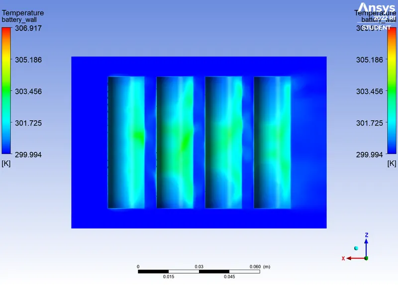
TEMPERATURE CONTOUR :
 |
 |
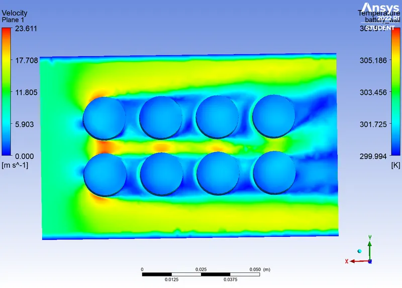
VELOCITY CONTOUR :
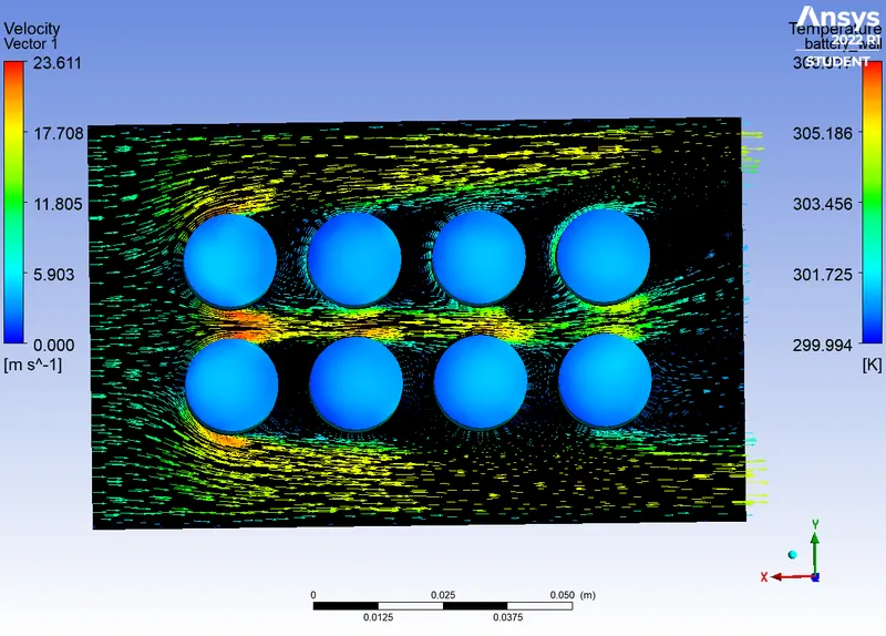
VELOCITY VECTOR :
CASE 6 :
MESH :
ELEMENT SIZE : 3mm
FACE SIZING : 2mm
INLET VELOCITY : 10m/s
DISTANCE BETWEEN BATTERY : 6mm
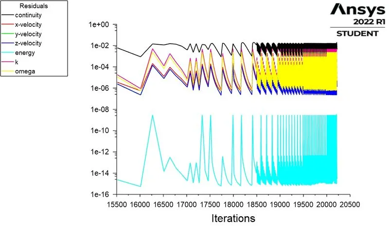
SOLVER : Transient state solver
PLOTS
|
RESIDUAL POLTS : |
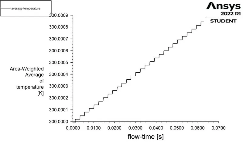
AVERAGE TEMPERATURE : |
|
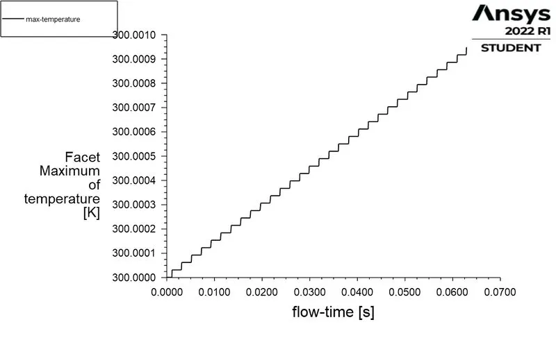
MAXIMUM TEMPERATURE : |
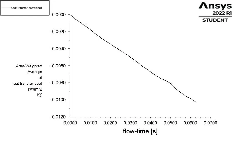
HEAT TRANSFER COEFFICIENT : |
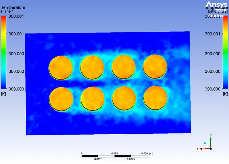
TEMPERATURE CONTOUR :
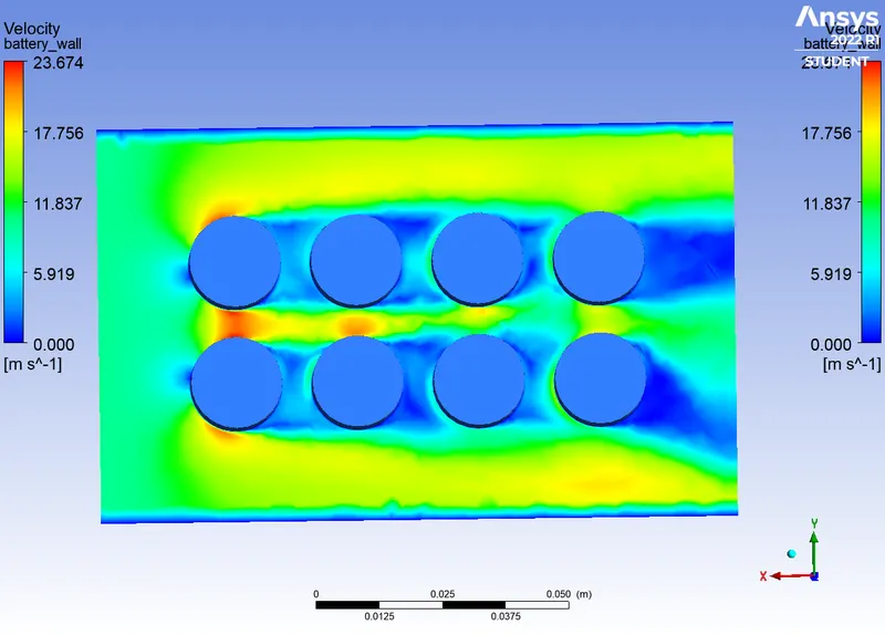
VELOCITY CONTOUR :
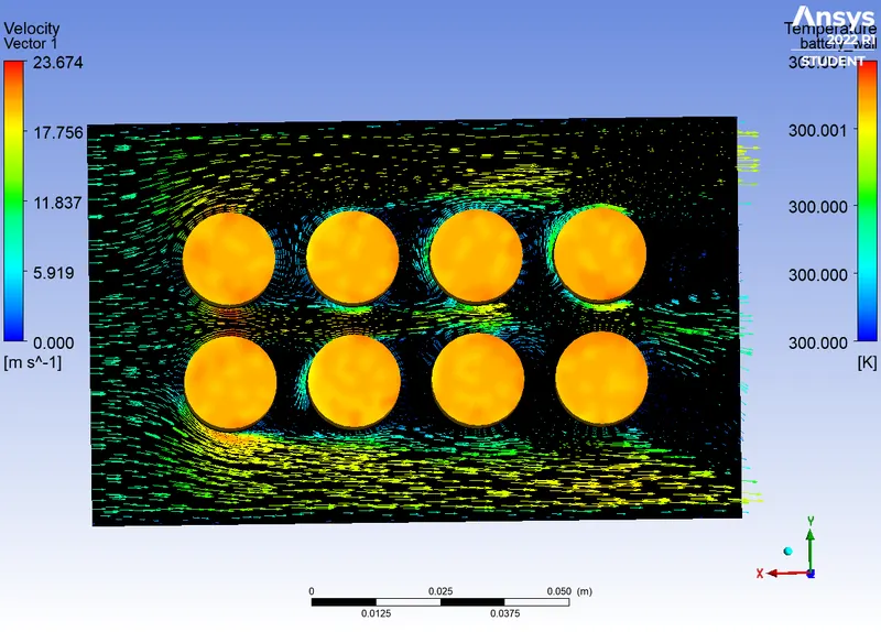
VELOCITY VECTOR:
TABULATION :
| CASES | ELEMENT SIZE | VELOCITY | DISTANCE BETWEEN BATTERIES | SOLVER TIME | AVERAGE TEMPERATURE | MAXIMUM TEMPERATURE | HEAT TRANSFER COEFFICIENT |
| 1 | 8mm | 3m/s | 2mm | Steady State | 304.3744 | 310.28156 | -11.99283 |
| 2 | 3mm | 3m/s | 2mm | Steady State | 304.72133 | 312.0424 | -11.8784 |
| 3 | 3mm | 5m/s | 2mm | Steady State | 303.21542 | 308.4342 | -12.90014 |
| 4 | 3mm | 10m/s | 2mm | Steady State | 301.7112 | 304.96368 | -14.20185 |
| 5 | 3mm | 10m/s | 4mm | Steady State | 301.5389 | 303.80743 | -14.5459 |
| 6 | 3mm | 10m/s | 6mm | Steady State | 301.5363 | 304.10403 | -14.3734 |
| 7 | 3mm | 10m/s | 6mm | Transient State | 300.00086 | 300.00095 | -0.0103 |
OBSERVATION :
GRID INDEPENDENT STUDY :
* From the first 2 cases we can observe that the 2nd case ( 3mm of element size ) gives better results than the 1st case. The maximum temperature case2 is higher than case 1.
* So it shows that when number of elements increase than the accuracy of the obtained results also increased. Then fine mesh size is used for more accurate solutions.
VARIOUS INLET VELOCITY :
* It can be observed from the table that when velocity is low the average and maximum temperature of batteries is higher.
* If the velocity of inlet air is high than the average and maximum temperature of batteries is loe. It shows that velocity increases than temperature decreses, that means both are recipolcal to eachother.
* If the velocity increase than heat tranfer coefficient increase and when velocity decreses than HTC also decresee.
* That shows heat transfer coefficient is directly propostional to the velocity.
* As we looking for higher heat transfer, It is better to use the higher velocity than the lower velocity.
* It is also observed that the increasing in heat transfer coefficient will reaches the saturation at certain velocity.
DISTANCE BETWEEN THE BATTERIES :
* As the distance between the batteries increase than the surface area of the pack is also increase.
* From the table we can observe, when the distance increases than heat transfer coefficient is not incresing evern the velocity is high.
* It shows that Heat transfer coefficient is decreasing when the surface area increases.
* For higher heat transfer coefficient it is better to use the less distance between batteries .
CONCLUSION :
* The simulation of battery pack is performed for different mesh size, various velocity, and comparied the distance of batteries to get more accurate heat transfer coefficient.
* As we looking for higher heat transfer, It is better to use the higher velocity than the lower velocity.
* The distance between batteries is less than HTC is higher.
* From all the results, we can conclude that for higher HTC, the velocity of inlet air should be high, and the distance between the battery should be less.
* The case 4 satisfies all the observed results, so case 4 will be suitable to deliver the output of higher heat transfer rate when compare to other cases.