Simulating Combustion of Natural Gas.
AIM :-
To simulate the combustion of natural gas to calculate the mass fraction & by adding the water in the fuel to observe the effects to avoid harmful effects on environment and human.
OBJECTIVE :-
- Perform a combustion simulation on the combustor model & plot the variation of the mass fraction of the different species.
- Add the water content in the fuel from 5% to 30% by mole & observe the effect of it on the results.
INTRODUCTION :-
Natural gas is an extremely important source of energy for reducing pollution & maintaining a clean and healthy environment. In addition to being a domestically abundant & secure source of energy, the use of natural gas also offers a number of environmental benefits over other sources of energy, particularly other fossil fuels.
THEORY :-
Natural gas is the cleanest of all the fossil fuels, as evidenced in the Environmental Protection Agency Composed primarily of methane. The main products of the combustion of natural gas are carbon dioxide & water vapour, the same compounds we exhale when we breathe.
Coal & oil are composed of much more complex molecules, with a higher carbon ratio & higher nitrogen & sulfur contents. This means that when combusted, coal & oil release higher levels of harmful emissions, including a higher ratio of carbon emissions, nitrogen oxides (NOx), & sulfur dioxide (SO2)
The combustion of natural gas, on the other hand, releases very small amounts of sulfur dioxide & nitrogen oxides, virtually no ash or particulate matter, lower levels of carbon dioxide, carbon monoxide & other reactive hydrocarbons.
Natural gas, emitting fewer harmful chemicals into the atmosphere than other fossil fuels, can help to mitigate some of these environmental issues. These issues include:
- Greenhouse Gas Emissions
- Smog, Air Quality & Acid Rain
- Industrial & Electric Generation Emissions
- Pollution from the Transportation Sector – Natural Gas Vehicles
Chemically, this combustion process consists of a reaction between methane & oxygen in the air.
Nitrogen Oxides :-
Nitrogen oxides formation occurs by three fundamentally different mechanisms.
The principal mechanism of NOx formation in natural gas combustion is thermal NOx. The thermal NOx mechanism occurs through the thermal dissociation and subsequent reaction of nitrogen (N2) and oxygen (O2) molecules in the combustion air. Most NOx formed through the thermal NOx mechanism occurs in the high temperature flame zone near the burners.
The formation of thermal NOx is affected by three furnace-zone factors:
- oxygen concentration,
- peak temperature, and
- time of exposure at peak temperature.
As these three factors increase, NOx emission levels increase. The emission trends due to changes in these factors are fairly consistent for all types of natural gas-fired boilers and furnaces.
Emission levels vary considerably with the type and size of combustor and with operating conditions (e.g., combustion air temperature, volumetric heat release rate, load, and excess oxygen level).
The second mechanism of NOx formation, called prompt NOx, occurs through early reactions of nitrogen molecules in the combustion air and hydrocarbon radicals from the fuel. Prompt NOx reactions occur within the flame and are usually negligible when compared to the amount of NOx formed through the thermal NOx mechanism. However, prompt NOx levels may become significant with ultra-low-NOx burners.
The third mechanism of NOx formation, called fuel NOx, steams from the evolution and reaction of fuel-bound nitrogen compounds with oxygen. Due to the characteristically low fuel nitrogen content of natural gas, NOx formation through the fuel NOx mechanism is insignificant.
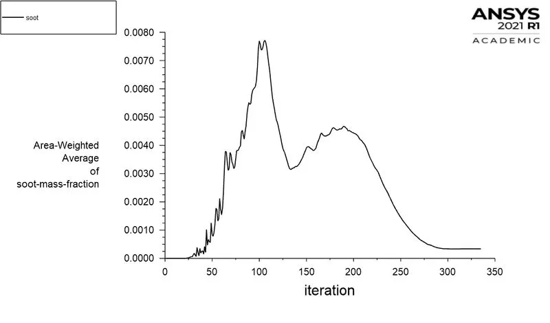
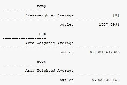
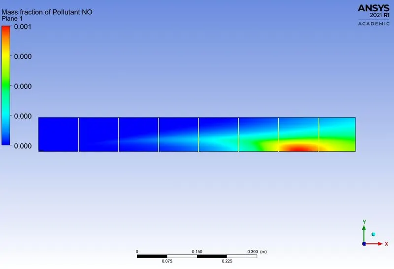
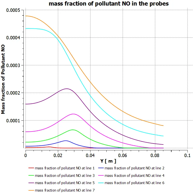
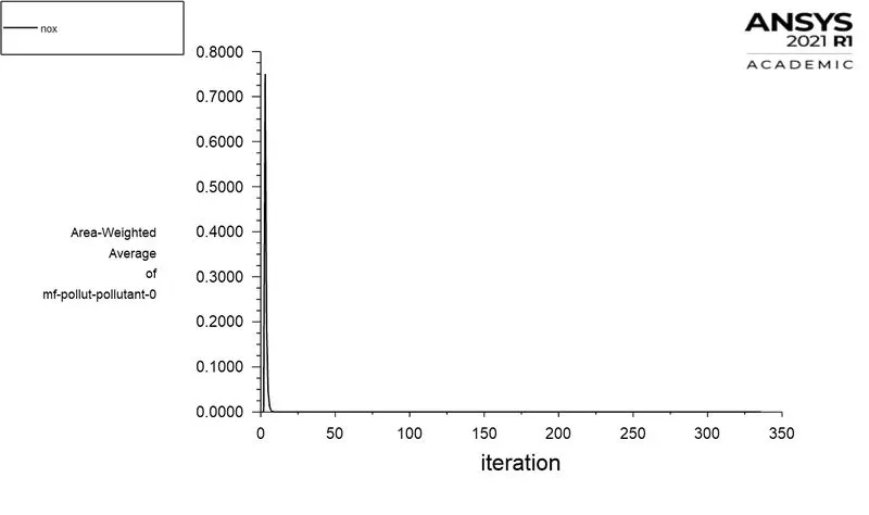
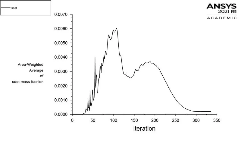
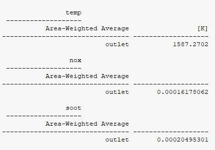
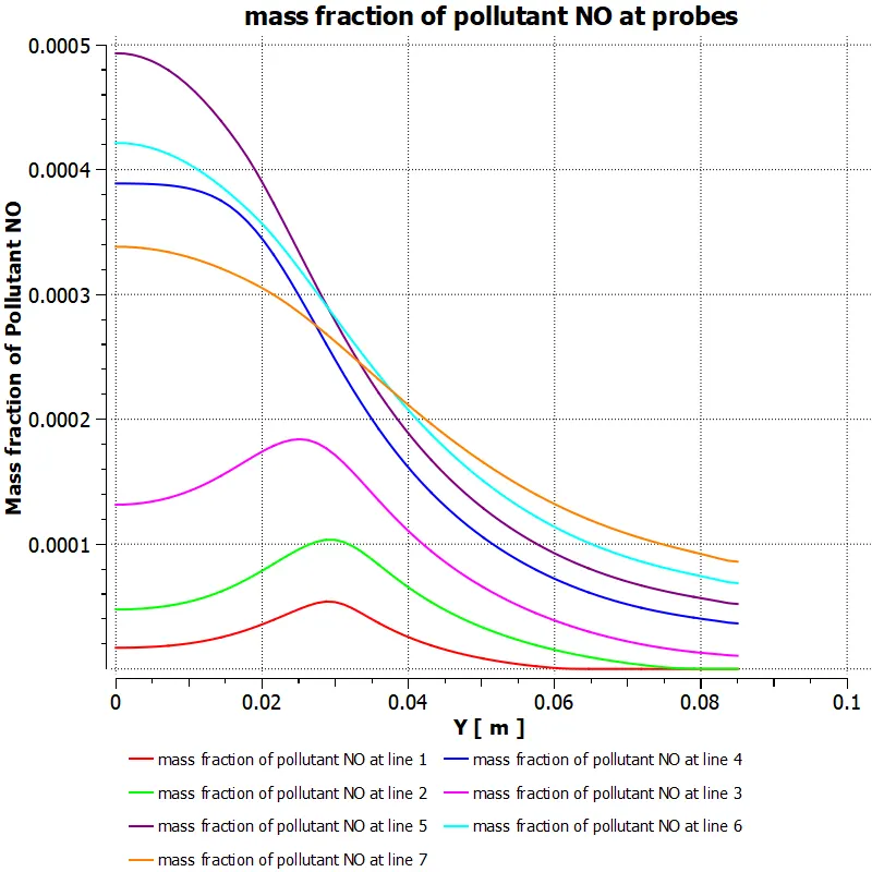
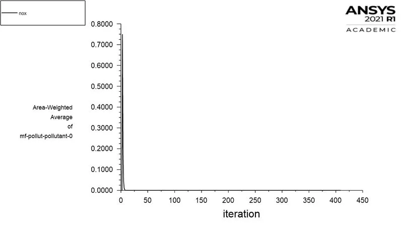
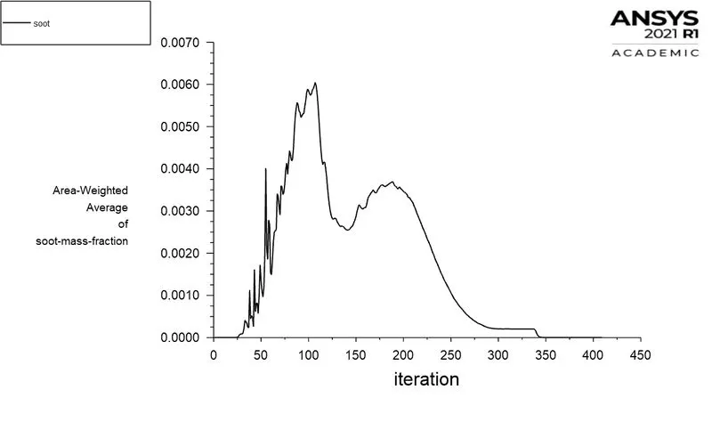
From the simulation, the Nox and soot is getting formed at the outlet of the combustor. Such formation has harmful effects on the environment and humans. The stringent government norms also demand the least formation of Nox and soot and to satisfy those requirements, check the effect of adding the water in the fuel.
Here by adding the water content in the fuel from 5% to 30% by mole and observe the effect of it on the results And line plots and contours are to prove.
MASS FRACTION :-
The ratio of mass of a component in a mixture to the total mass of mixture is known as mass fraction.
MOLE FRACTION :-
The ratio of number of molecule of one component of solution or other mixture to the total number of moles representing all of the components.
SPACECLAIM :-
1. Combustion Model :-
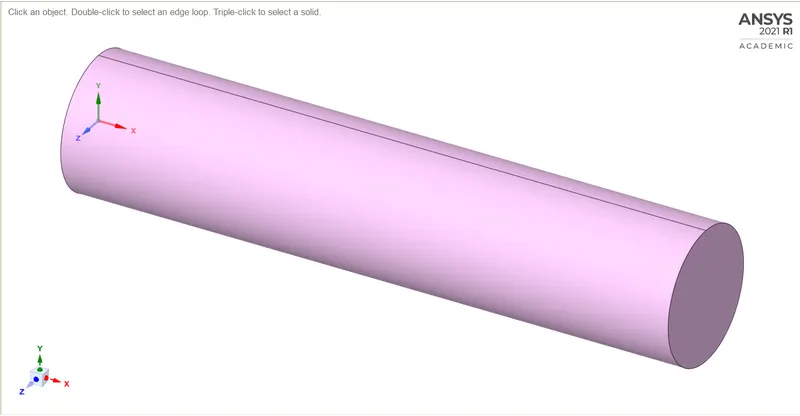
- This is 3D model, we can't run simulation for entire 3D model, it will cost a lot interms of time.
- So instead of 3D, We will perform simulation on 2D geometry, which is Axis-symmetric.
- For 2D geomerty we have to cut 3D model in two parts, and extract 2D geometry of the quadrant portion
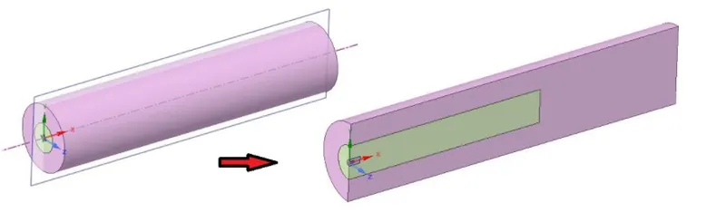
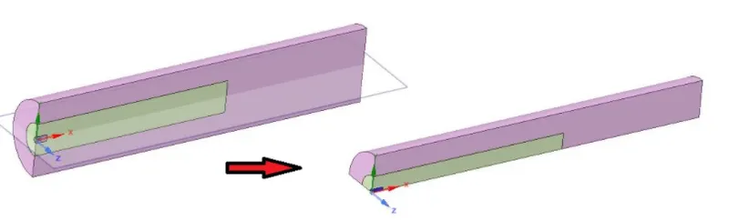
- Then we copy all faces from X-Y plane and paste it in New Design
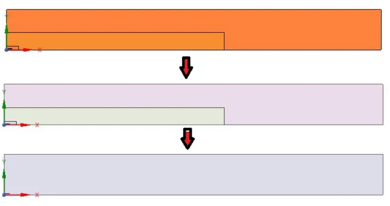
- Then we paste it only in X-Y plane.
- After pasting, we merge all faces by using 'combine' command and can make it a single surface.
- So the 2D geometry can be ready for further process
Mesh :-
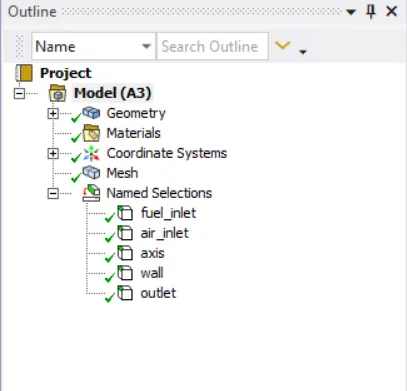
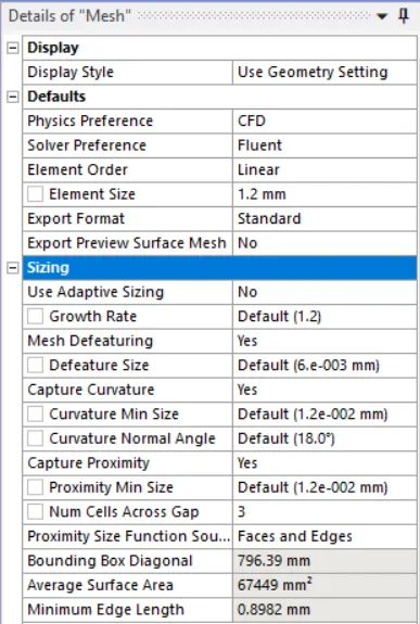
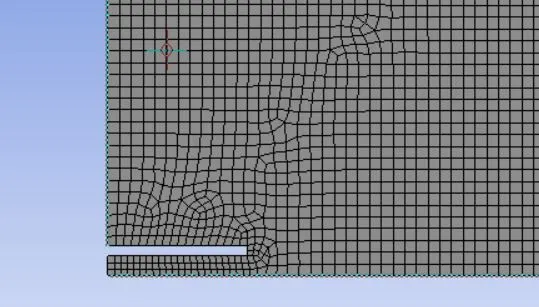
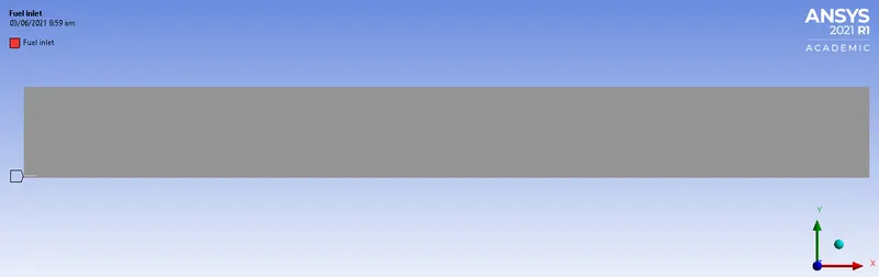
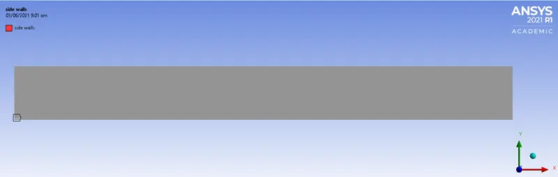
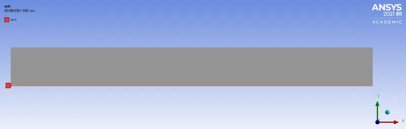
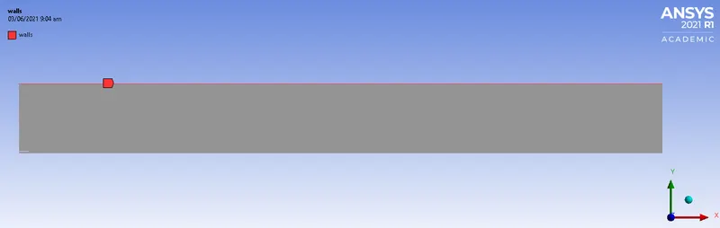
Model was imported from Spaceclaim and tia mesh was deployed with element size 1mm. Named selection was created like fuel inlet, air inlet, wall etc, these used for boundary conditions in solver setup.
Mesh parameters -
Generated Mesh -

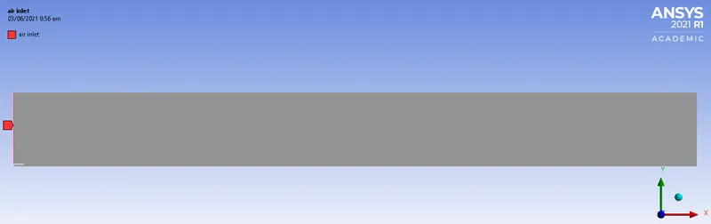
Named selections:
Air inlet (Type Velocity inlet)
Fuel inlet (Type Velocity inlet)
Side Walls (Type Wall)
Axis (Type Axis)
Walls (Type Wall)
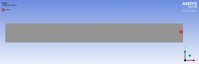
Outlet (Type Pressure outlet)
Fluent set-up :-
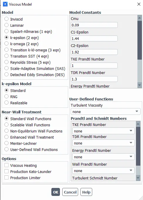
1.Standard K-epsilon turbulence model with standard wall function is chosen as we are interested in the analysis of the combustion reaction than the wall phenomenons.
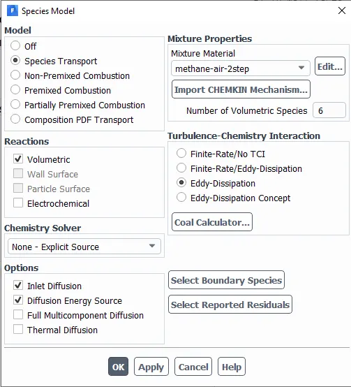
2. Species model is chosen as species transport as there is a separate inlet for air and fuel. The fuel chosen is methane-air. The volumetric combustion phase of the model is chosen. The combustion
3. Chemical interaction chosen is the Eddy dissipation model. This model is chosen because it requires less computational time when compared to other models and also requires fewer hardware requirements. In this model, the start time of combustion is calculated based on the turbulence kinetic energy 'k' and epsilon. Here the heat source of the combustion is the turbulence of the fuel mixture.
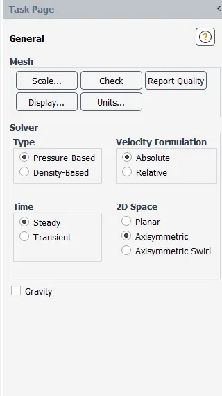
4. Axis symmetric model is chosen as the bottom of the model axis boundary condition is applied.
General settings:
Viscous model and species:
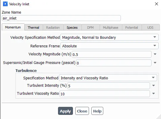
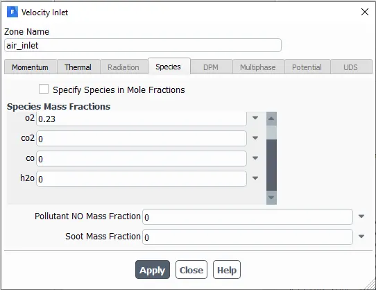
Air inlet:
Fuel inlet:
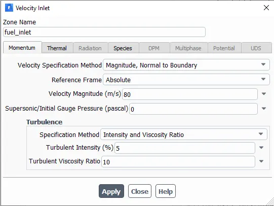
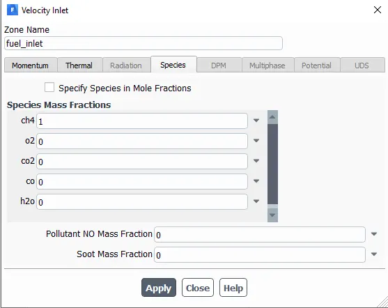
PART 1:
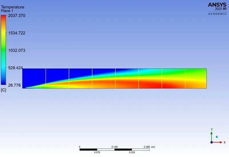
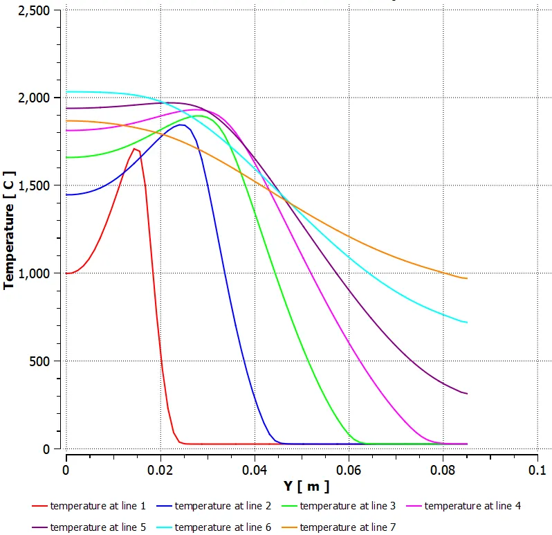
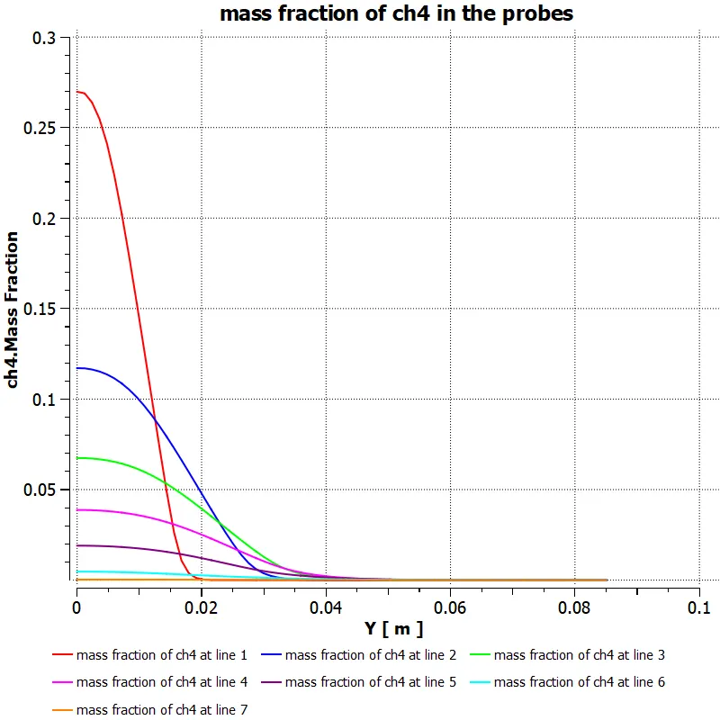
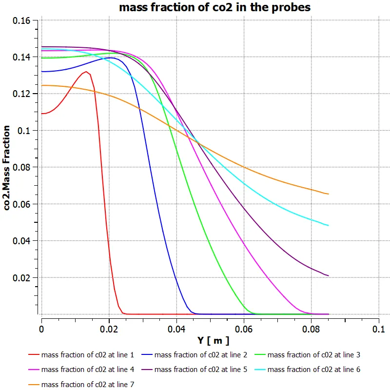
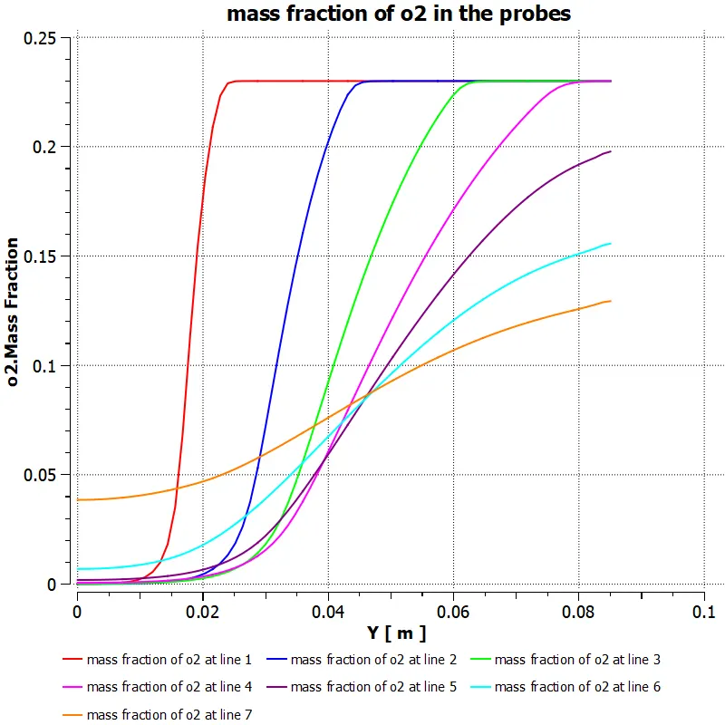
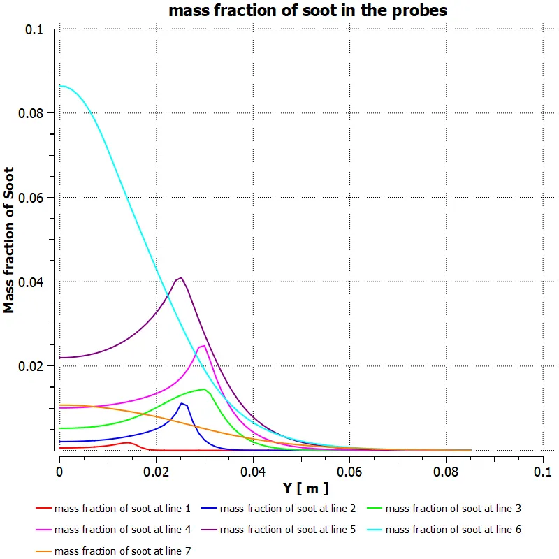
Perform a combustion simulation on the combustor model and plot the variation of the mass fraction of the different species’ in the simulation using line probes at different locations of the combustor as shown in Fig. You need to plot for CO2, H2O, CH4, N2, O2, NOx emissions & Soot formation.
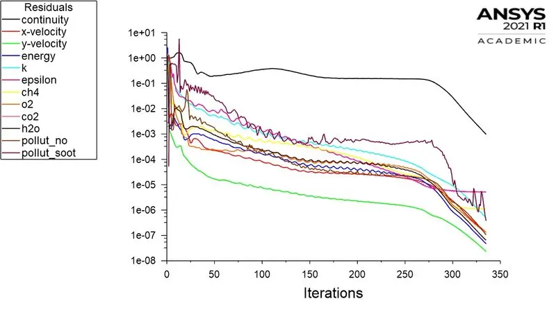
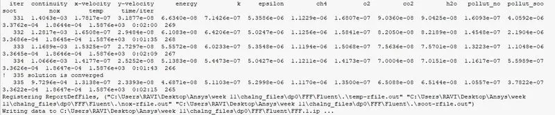
Residuals:
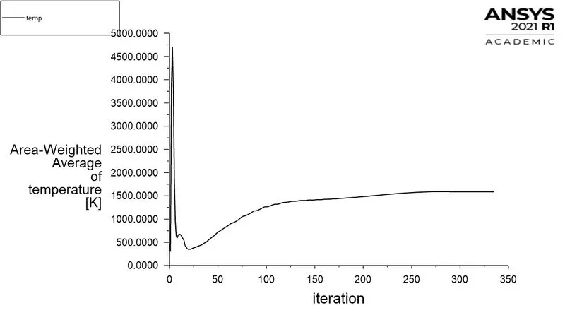
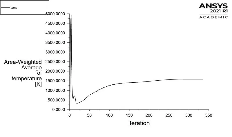
Area-weighted Avergae temperature:
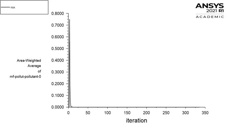
Area-Weighted Average of mass fraction of Pollutant NOX
Area-Weighted Average of mass fraction of soot
Temperature contour
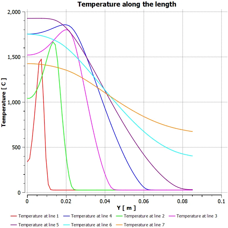
temperature along the probes
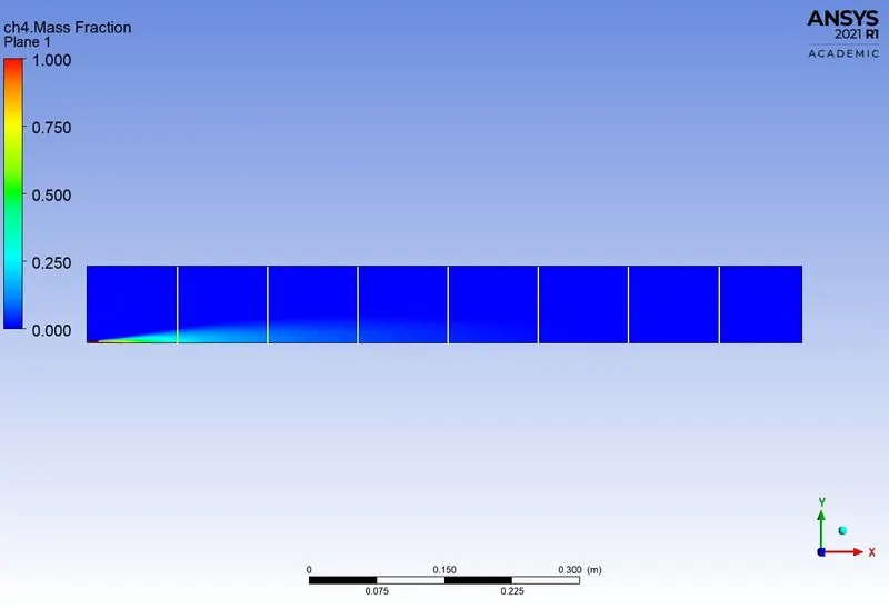
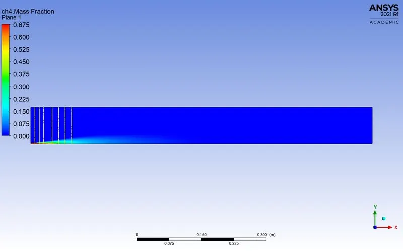
Mass fraction of ch4
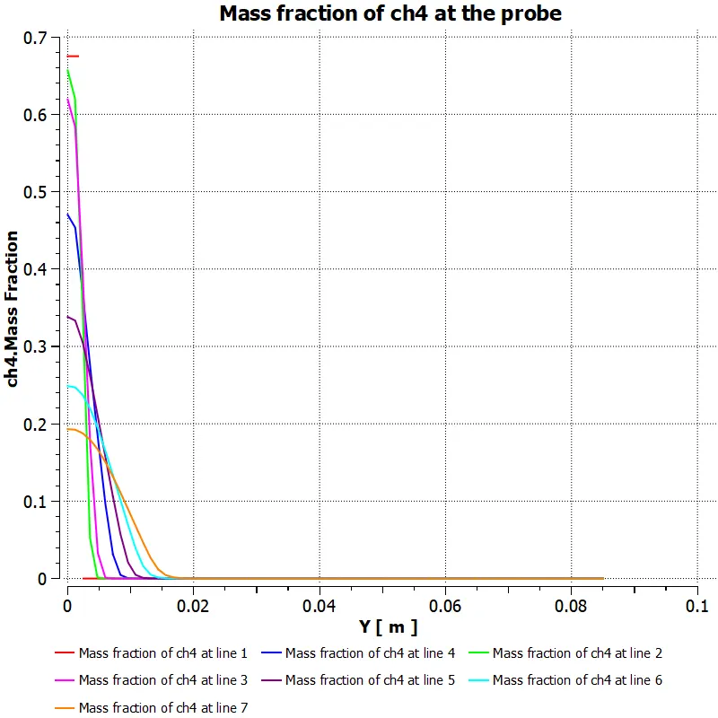
Mass fracton of ch4 along the above line probes
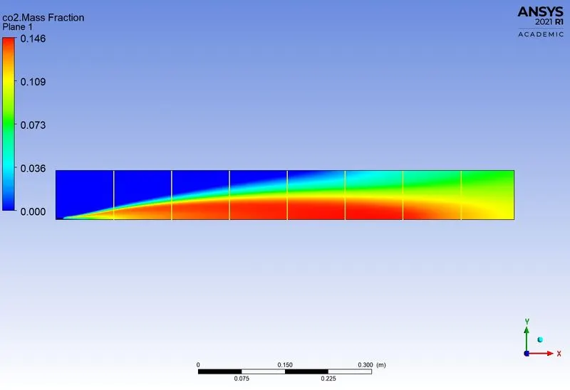
Mass fraction of Co2
Mass fracton of co2 along the above line probes
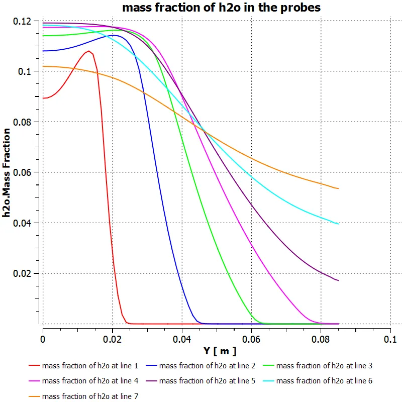
Mass fraction of h2o
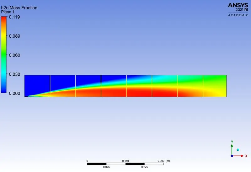
Mass fracton of h2o along the above line probes
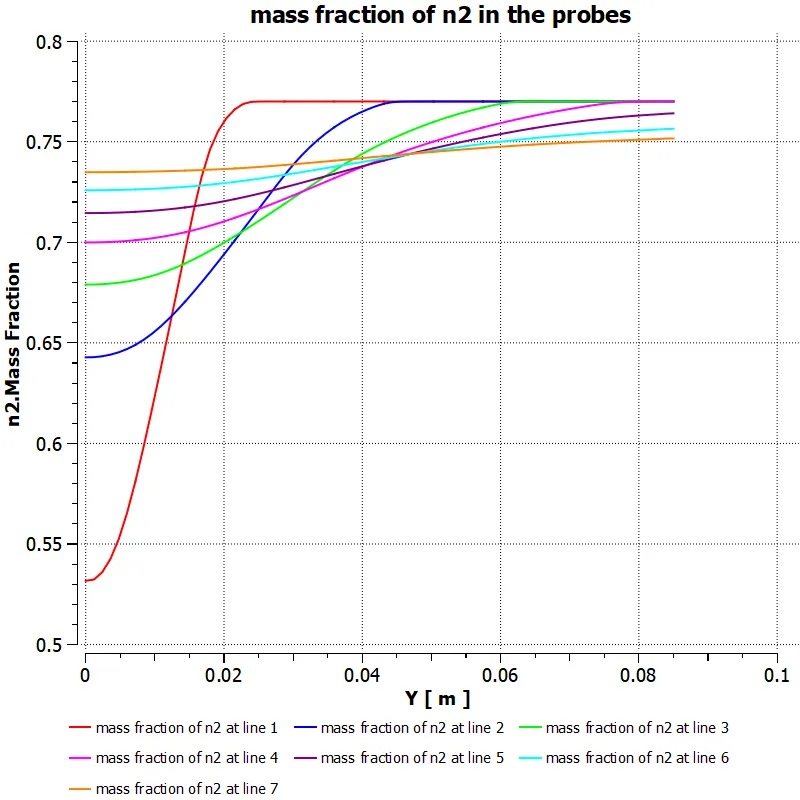
Mass fraction of n2
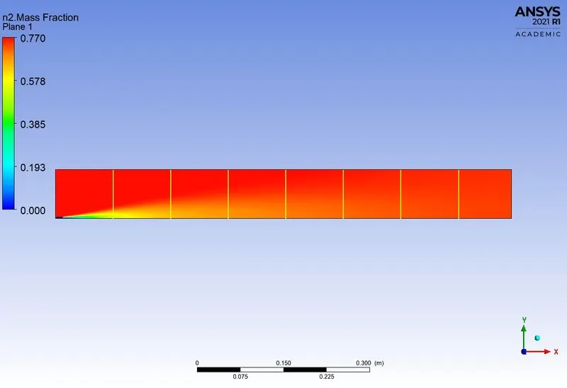
Mass fracton of n2 along the above line probes
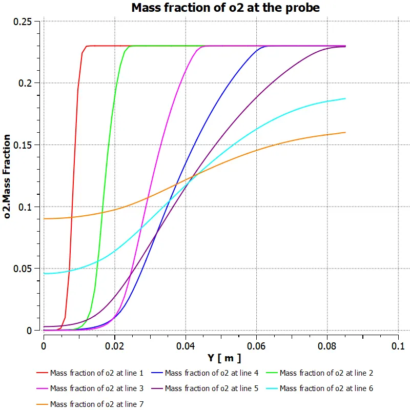
Mass fraction of o2
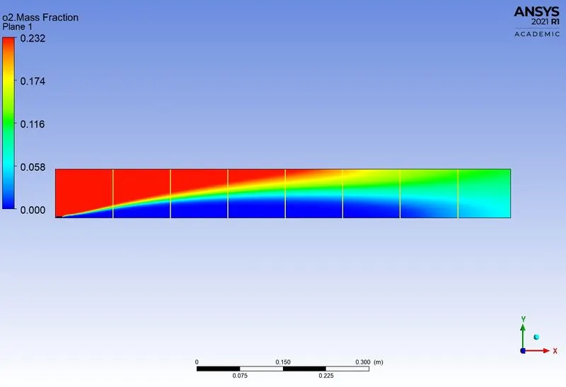
Mass fracton of o2 along the above line probes
Mass fraction of pollutant NOx
Mass fracton of pollutant NOx along the above line probes
Mass fraction of soot
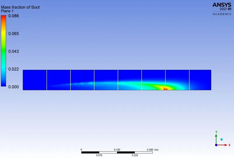
Mass fracton of soot along the above line probes
PART 2:
As you must have observed from the above simulation, the Nox and soot is getting formed at the outlet of the combustor. Such formation has harmful effects on the environment and humans. The stringent government norms also demand the least formation of Nox and soot and to satisfy those requirements, you need to check the effect of adding the water in the fuel.
In this part, you need to add the water content in the fuel from 5% to 30% by mole and observe the effect of it on the results. It is necessary to provide line plots and contours to prove your claim.
CASE 1
Air-inlet velocity = 0.5m/s, Thermal temperature=300K, Species mixture O2=0.23
Fuel-inlet velocity = 80m/s, Thermal temperature=300K, Species mixture CH4 =1
CASE 2 Adding 5% by mole of water into the fuel mixture
Air-inlet velocity = 0.5m/s, Thermal temperature=300K, Species mixture O2=0.23
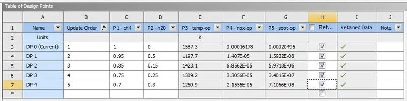
Fuel-inlet velocity = 80m/s, Thermal temperature=300K, Species mixture CH4 =0.95,H2O=0.5
CASE 3 Adding 15% by mole of water into the fuel mixture
Air-inlet velocity = 0.5m/s, Thermal temperature=300K, Species mixture O2=0.23
Fuel-inlet velocity = 80m/s, Thermal temperature=300K, Species mixture CH4 =0.85,H2O=0.15
CASE 4 Adding 25% by mole of water into the fuel mixture
Air-inlet velocity = 0.5m/s, Thermal temperature=300K, Species mixture O2=0.23
Fuel-inlet velocity = 80m/s, Thermal temperature=300K, Species mixture CH4 =0.75,H20=0.25
CASE 5 Adding 30% by mole of water into the fuel mixture
Air-inlet velocity = 0.5m/s, Thermal temperature=300K, Species mixture O2=0.23
Fuel-inlet velocity = 80m/s, Thermal temperature=300K, Species mixture CH4 =0.7,H2O=0.3
Hybrid initialisation is done
Number of iteration = 600
Case 1: ch4=1 and h2o=0
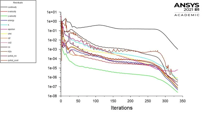
Residuals

Area-weighted Avergae temperature:
Area-Weighted Average of mass fraction of Pollutant NOX
Area-Weighted Average of mass fraction of soot
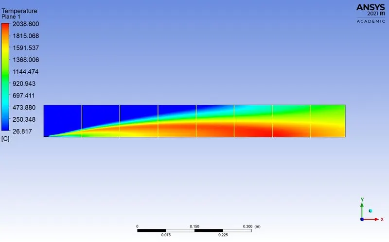
Temperature contour
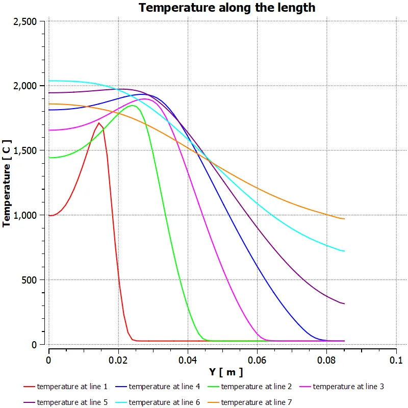
temperature along the probes
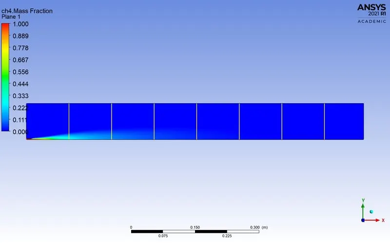
Mass fraction of ch4
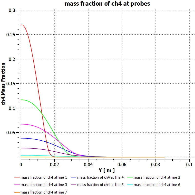
Mass fracton of ch4 along the above line probes
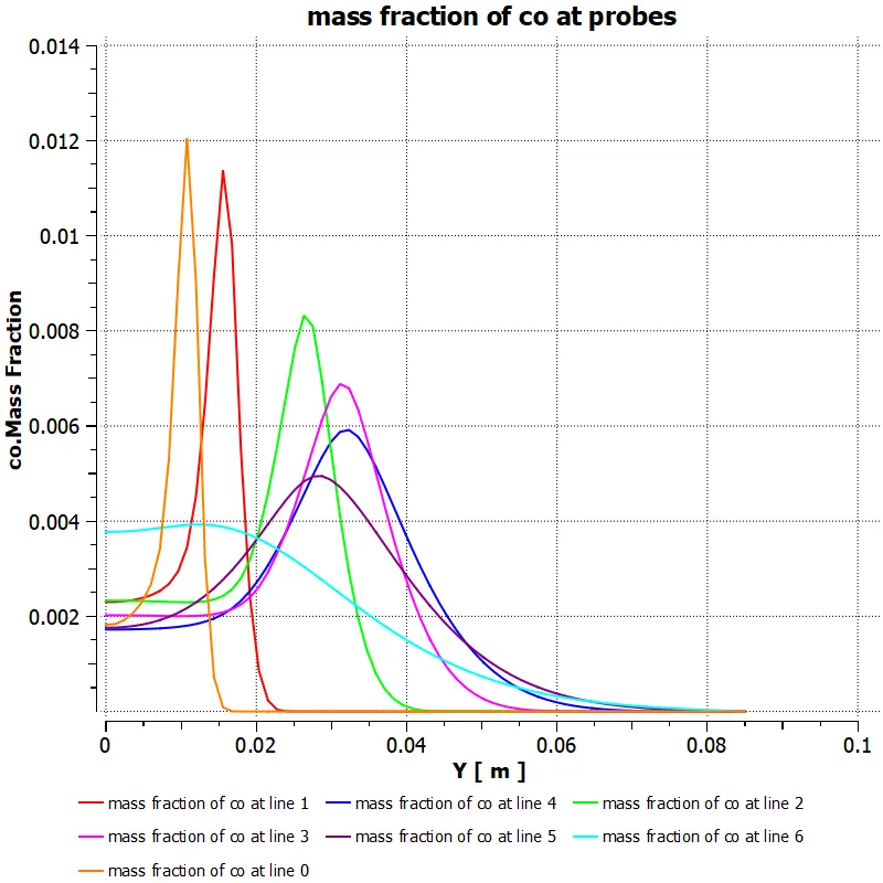
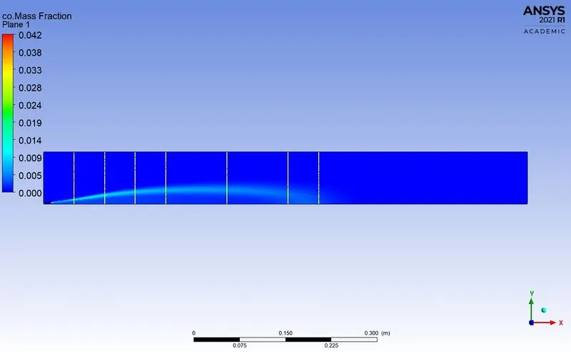
Mass fraction of co
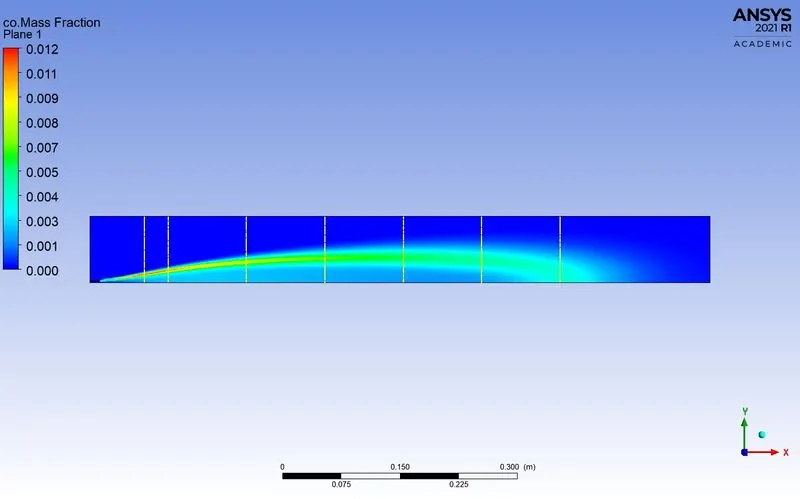
Mass fracton of co along the above line probes
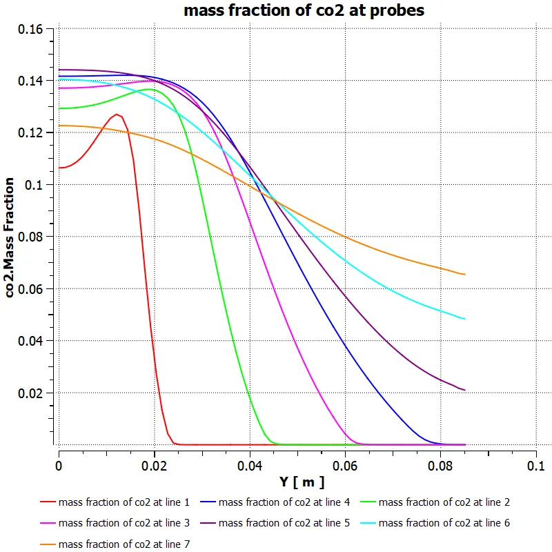
Mass fraction of co2
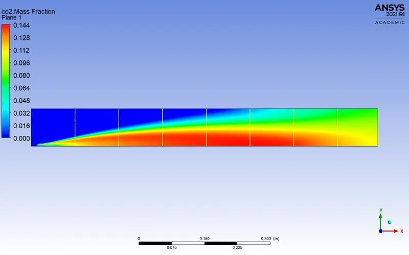
Mass fracton of co2 along the above line probes
Mass fraction of h2o
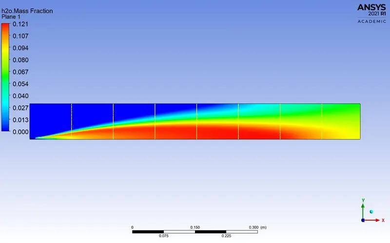
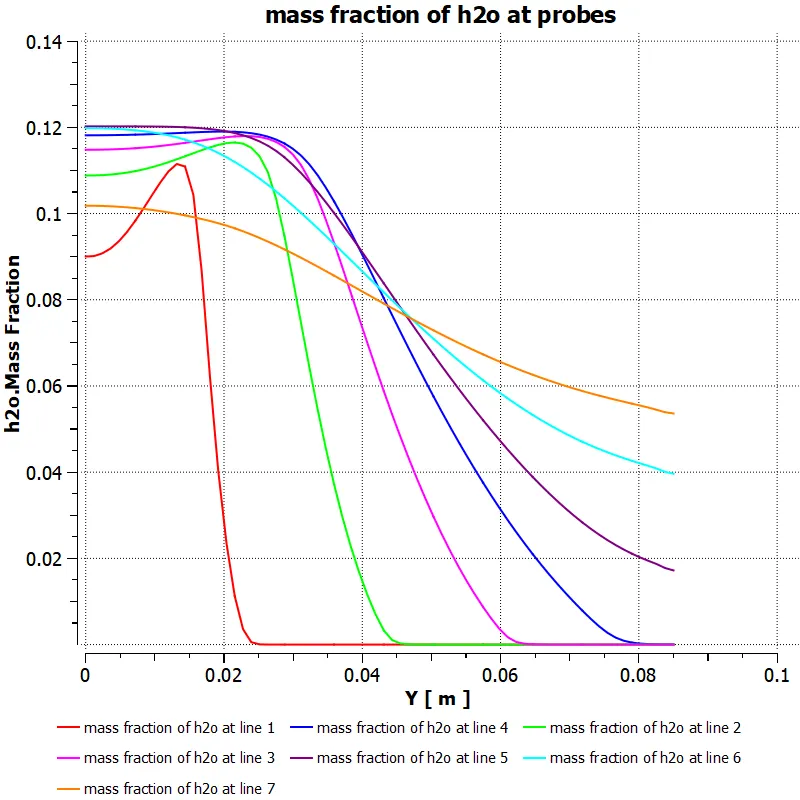
Mass fracton of h2o along the above line probes
Mass fraction of n2
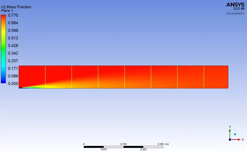
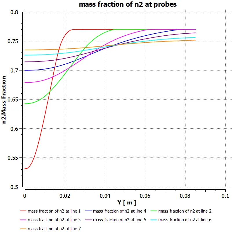
Mass fracton of n2 along the above line probes
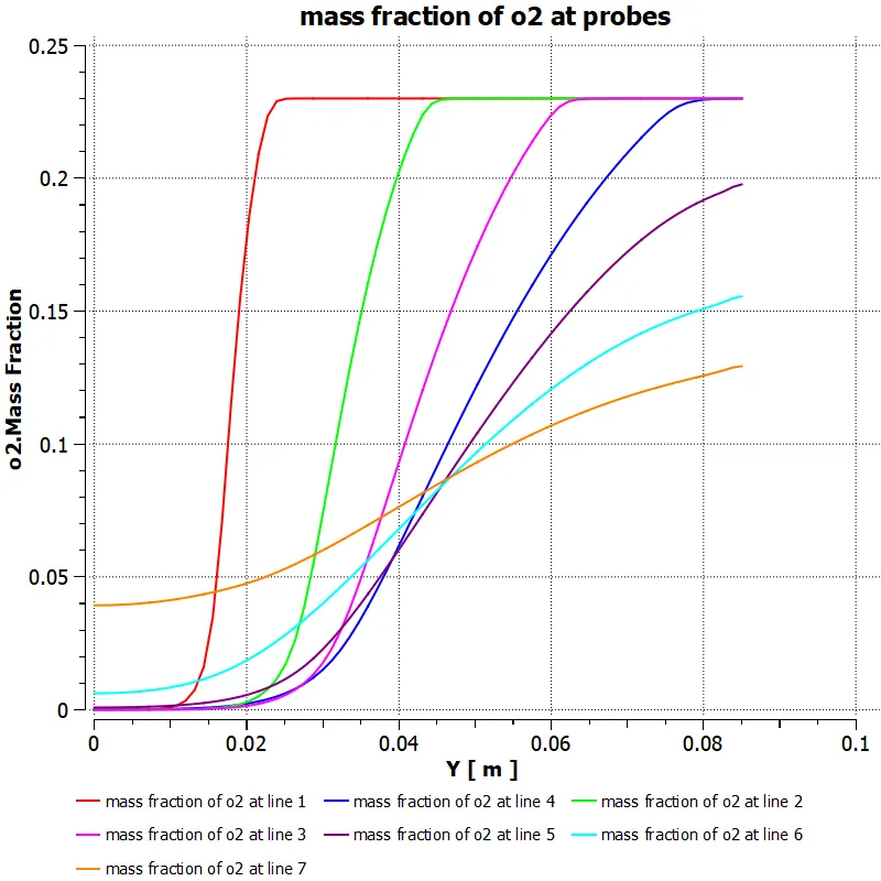
Mass fraction of o2
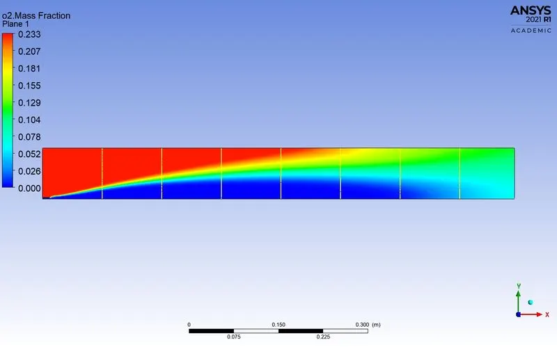
Mass fracton of o2 along the above line probes
Mass fraction of pollutant NOx
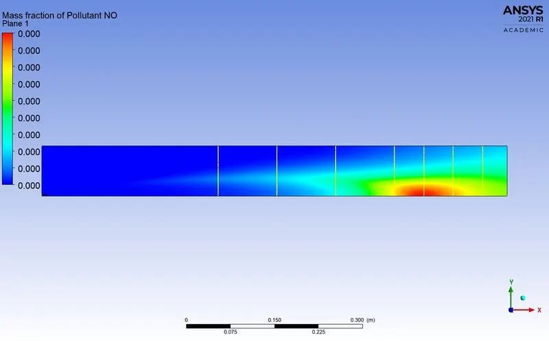
Mass fracton of pollutant NOx along the above line probes
Mass fraction of soot
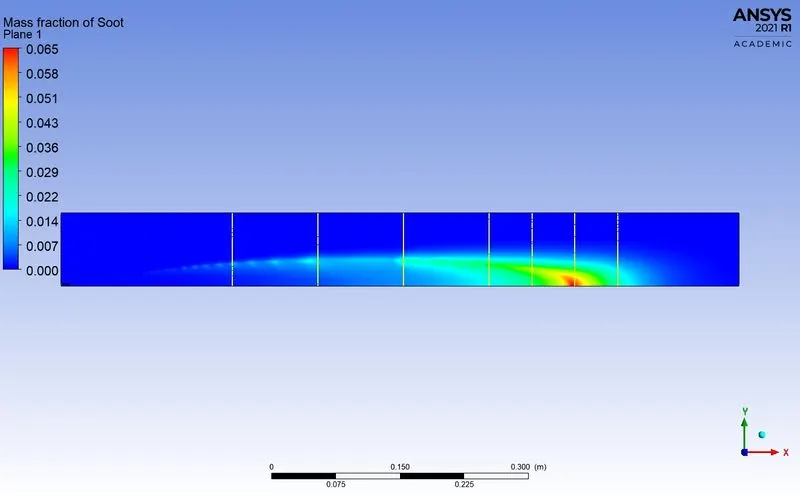
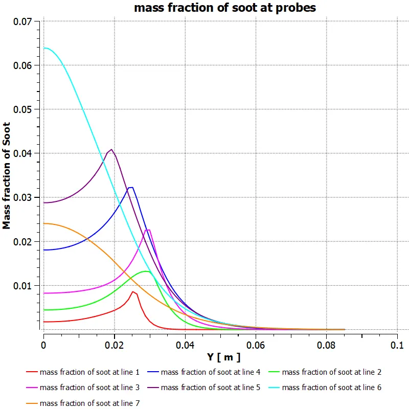
Mass fracton of soot along the above line probes
Case 2: ch4=0.95 and h2o=0.5
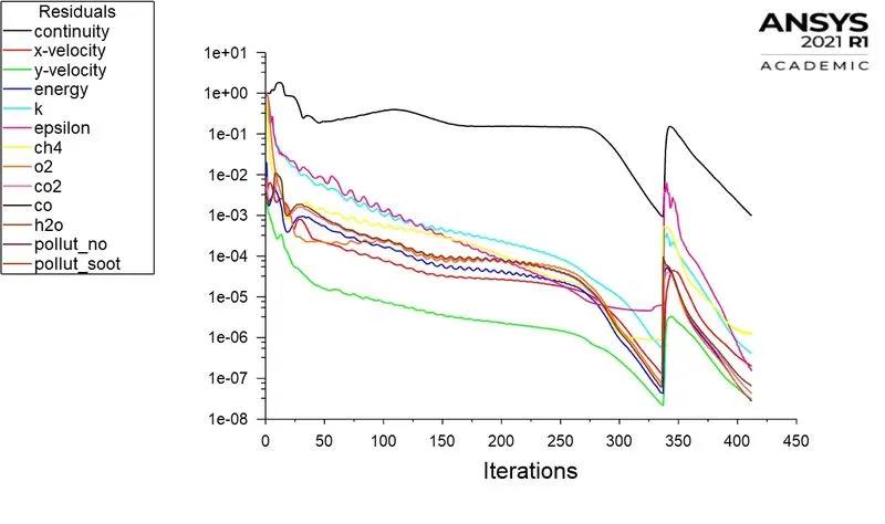
Residuals
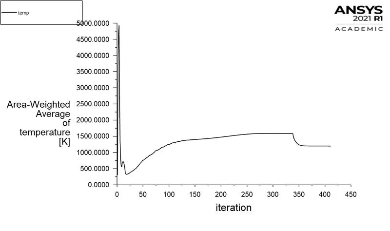
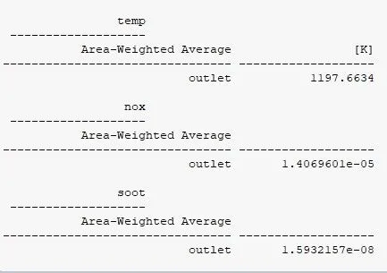
Area-weighted Avergae temperature:
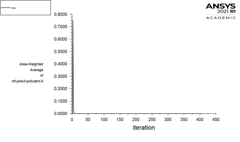
Area-Weighted Average of mass fraction of Pollutant NOX
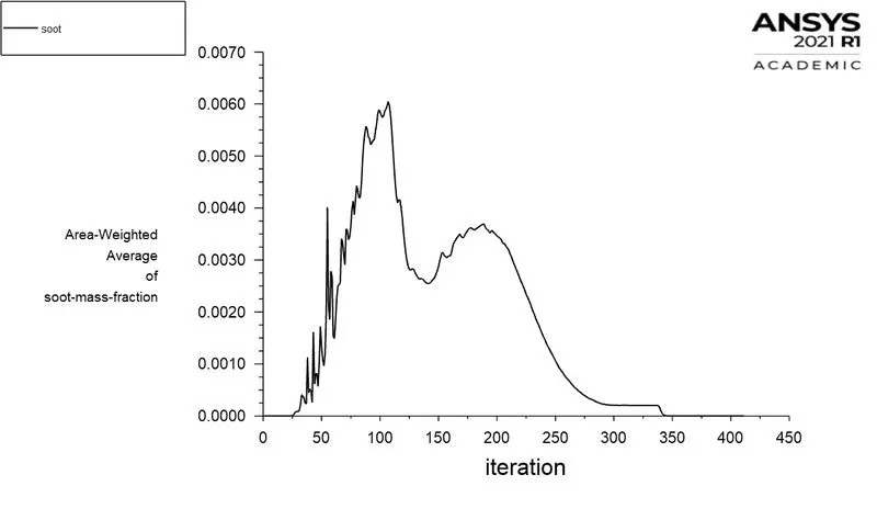
Area-Weighted Average of mass fraction of soot
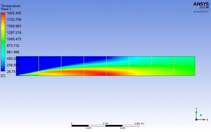
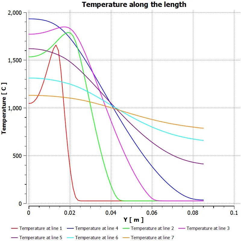
Temperature contour
temperature along the probes
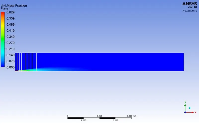
Mass fraction of ch4
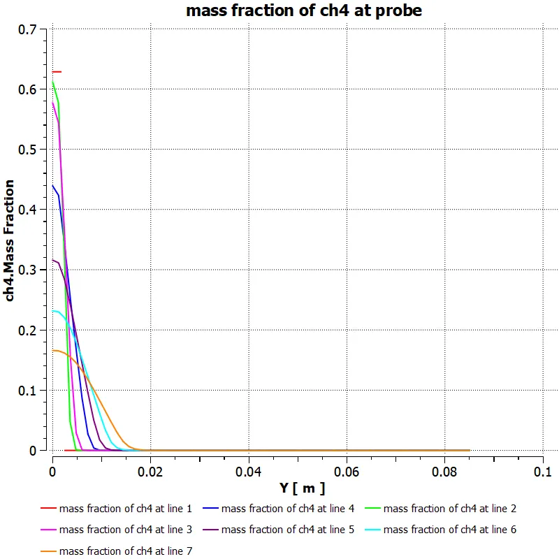
Mass fracton of ch4 along the above line probes
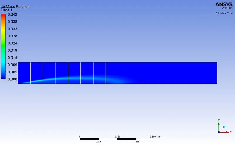
Mass fraction of co
Mass fracton of co along the above line probes
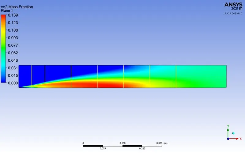
Mass fraction of co2
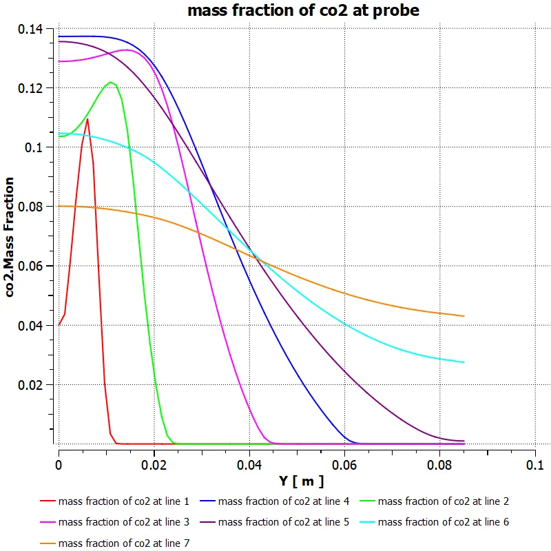
Mass fracton of co2 along the above line probes
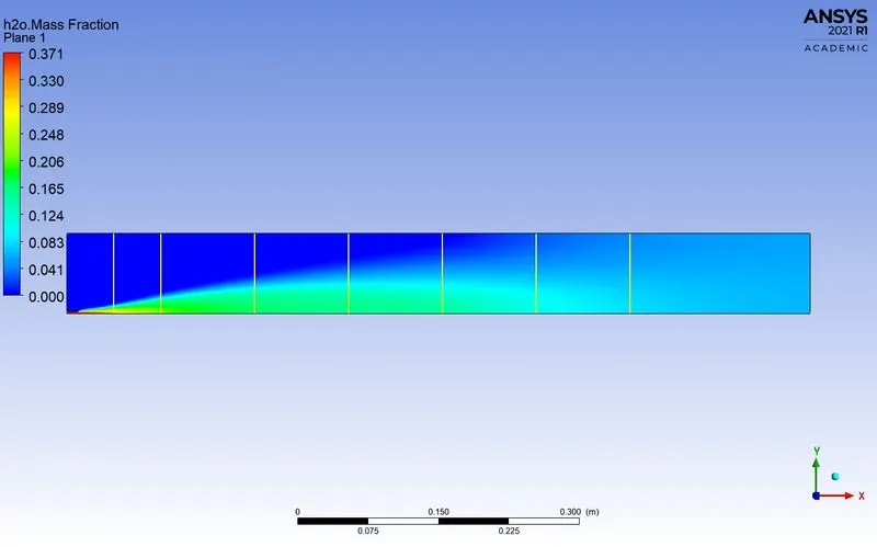
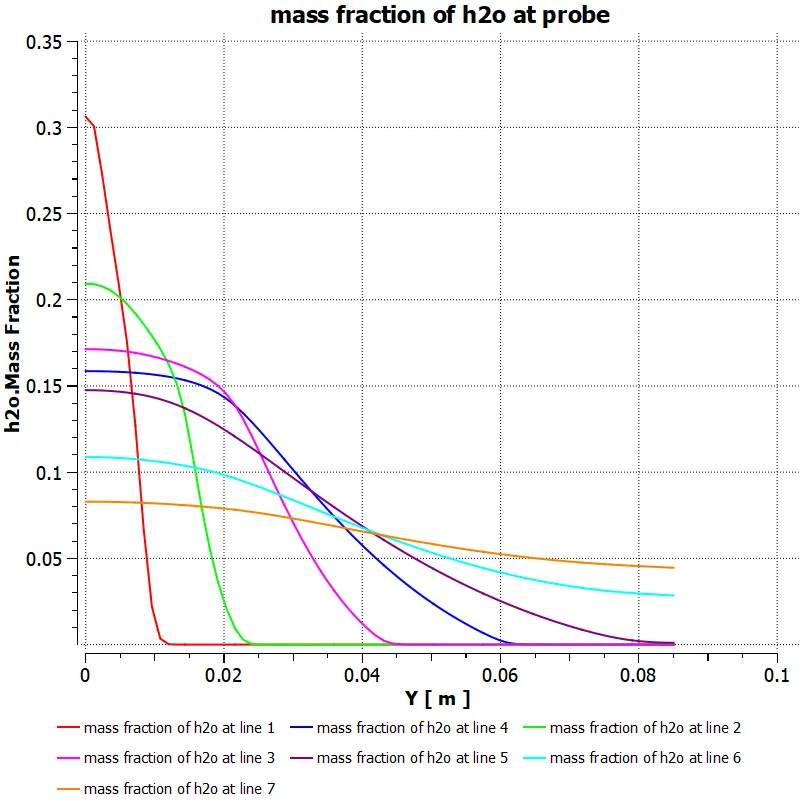
Mass fraction of h2o
Mass fracton of h2o along the above line probes
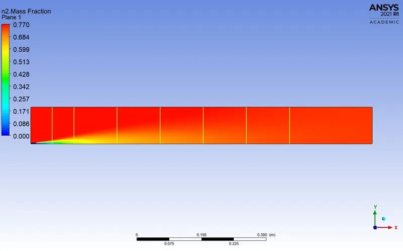
Mass fraction of n2
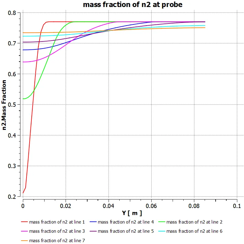
Mass fracton of n2 along the above line probes
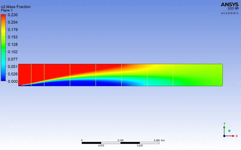
Mass fraction of o2
Mass fracton of o2 along the above line probes
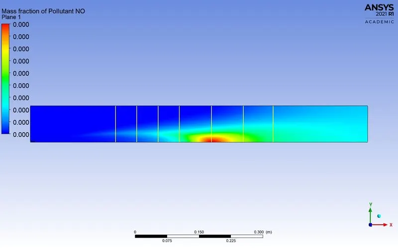
Mass fraction of pollutant NOx
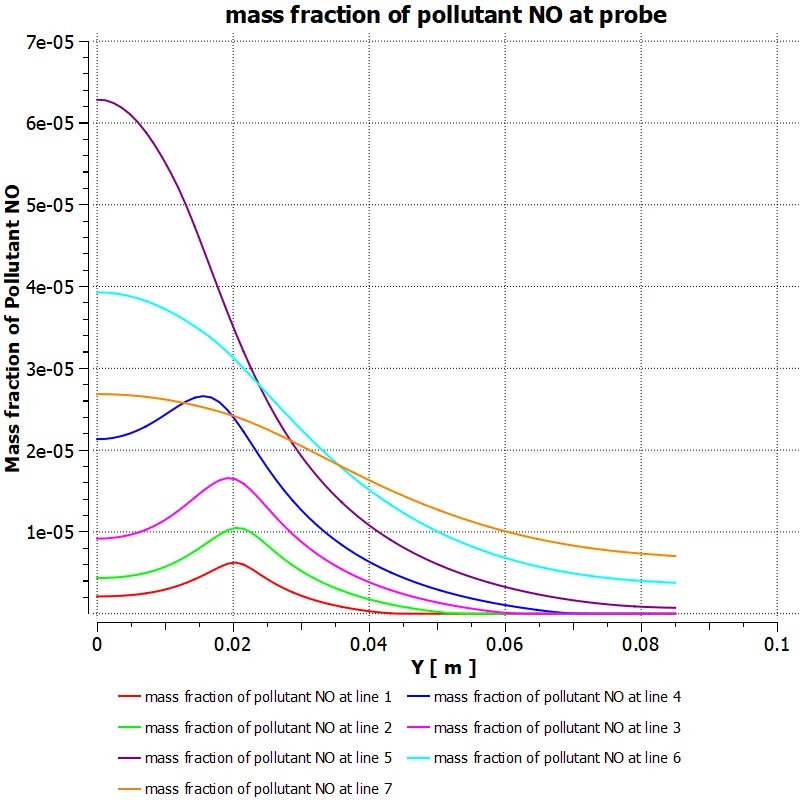
Mass fracton of pollutant NOx along the above line probes
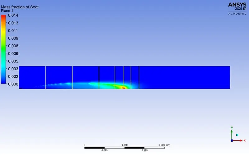
Mass fraction of soot
Mass fracton of soot along the above line probes
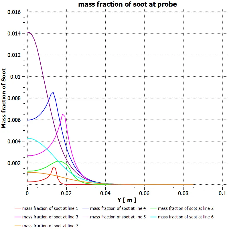
Case 3: ch4=0.85 and h2o=0.15
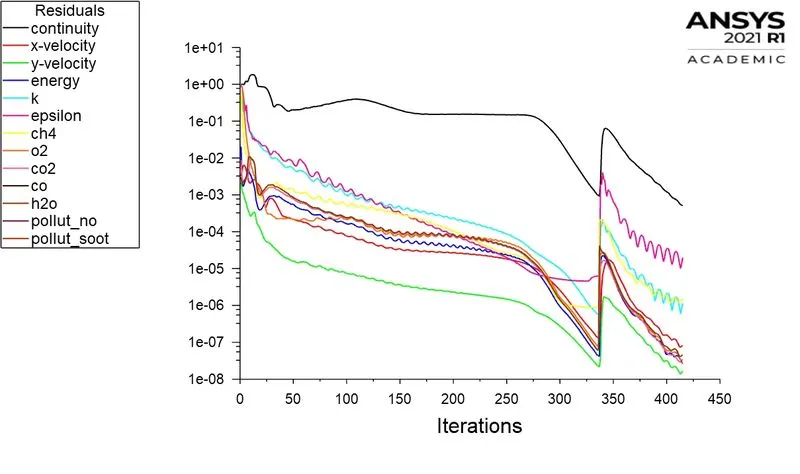
Residuals
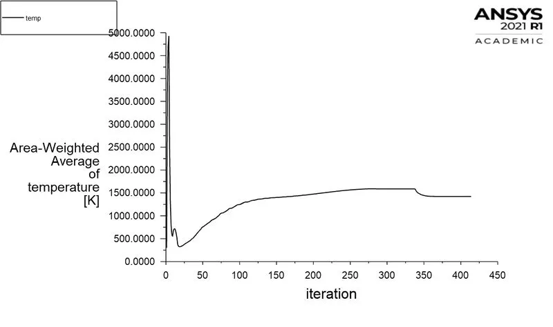
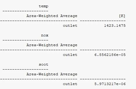
Area-weighted Avergae temperature:
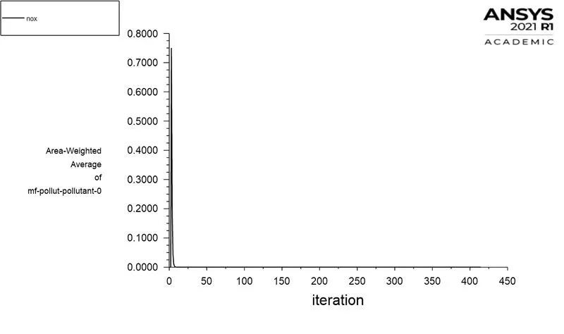
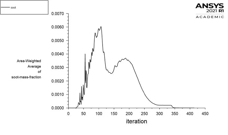
Area-Weighted Average of mass fraction of Pollutant NOX
Area-Weighted Average of mass fraction of soot
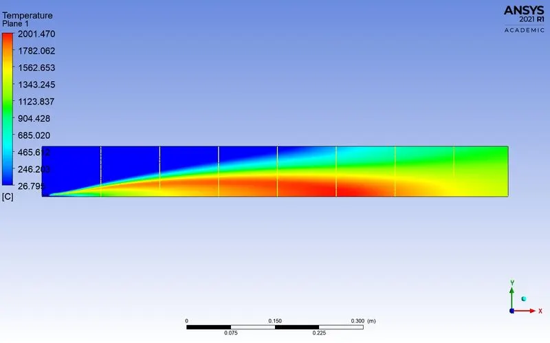
Temperature contour
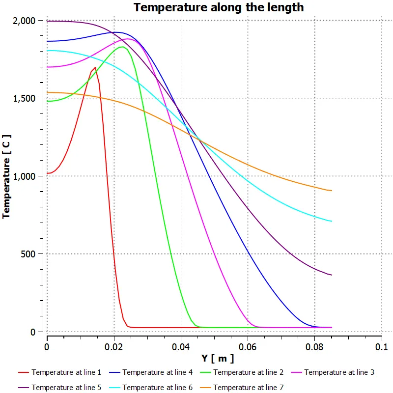
temperature along the probes
Mass fraction of ch4
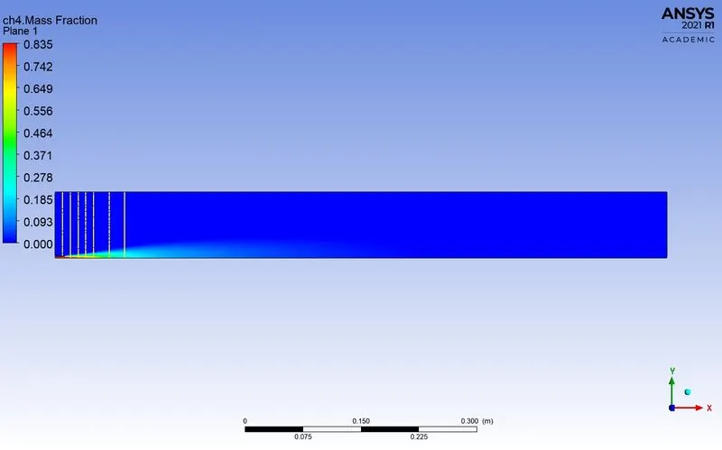
Mass fracton of ch4 along the above line probes
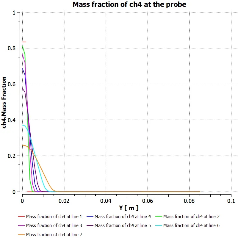
Mass fraction of co
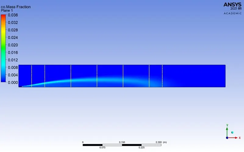
Mass fracton of co along the above line probes
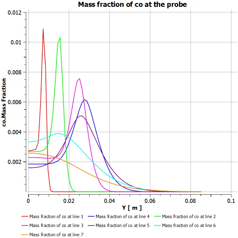
Mass fraction of co2
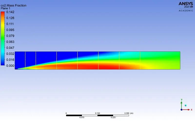
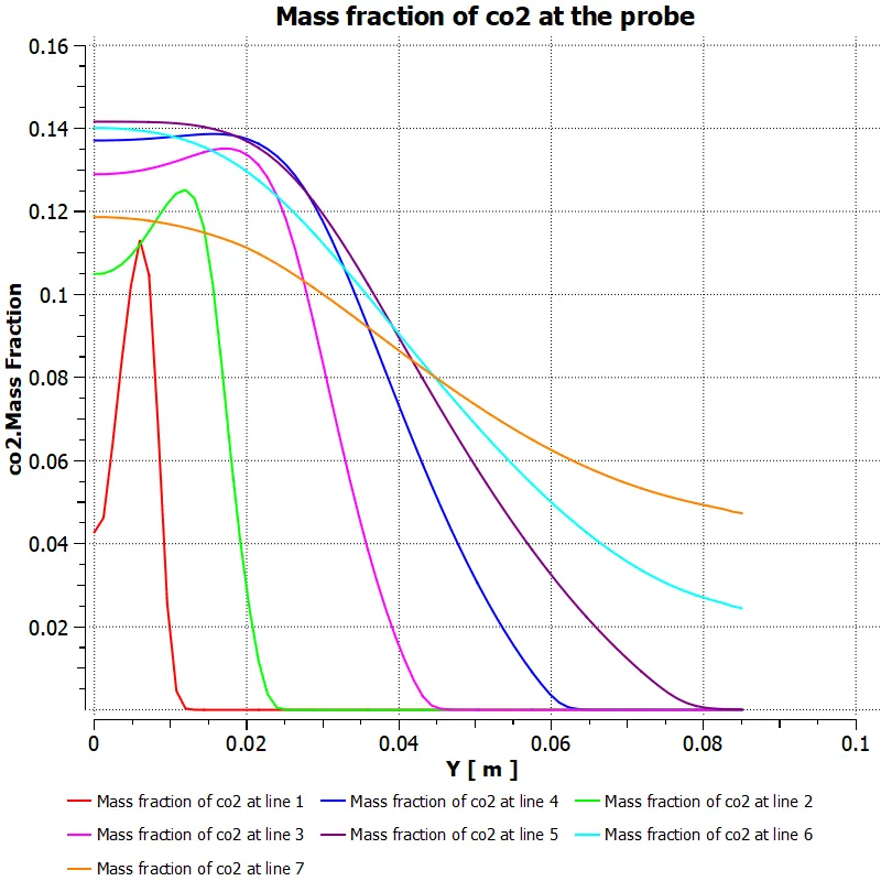
Mass fracton of co2 along the above line probes
Mass fraction of h2o
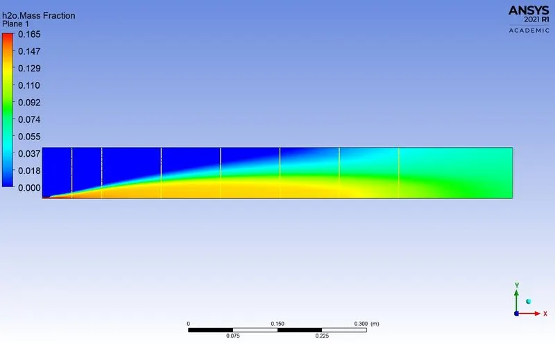
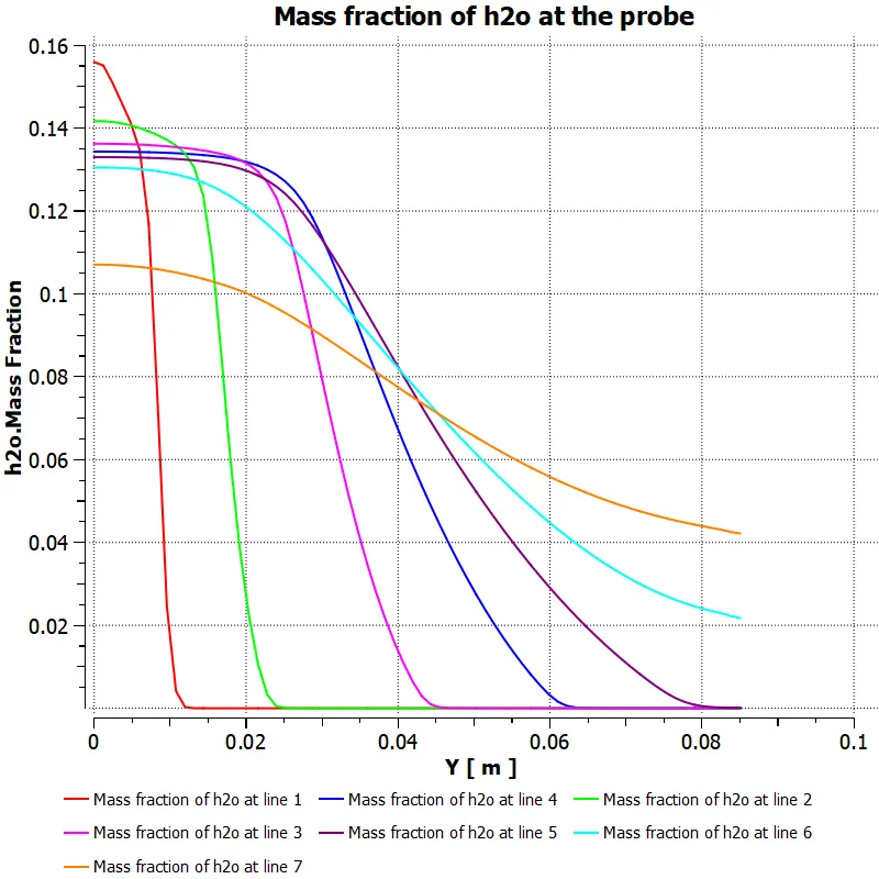
Mass fracton of h2o along the above line probes
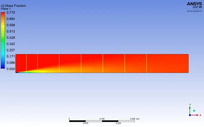
Mass fraction of n2
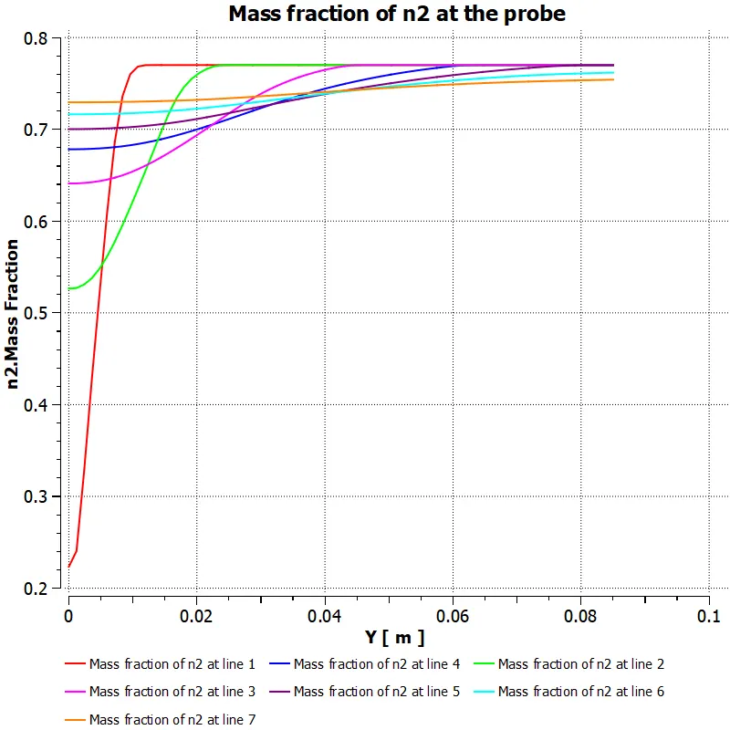
Mass fracton of n2 along the above line probes
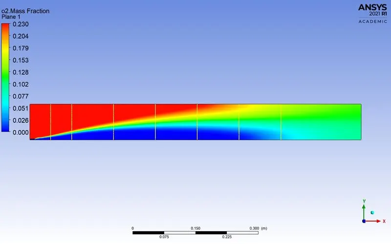
Mass fraction of o2
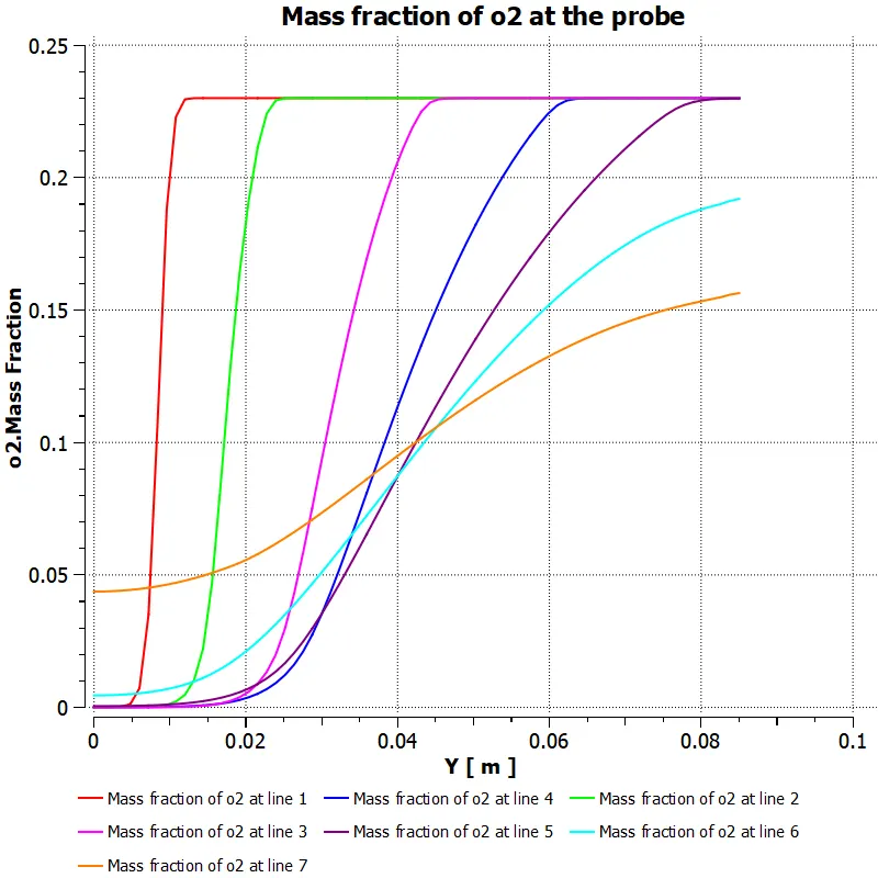
Mass fracton of o2 along the above line probes
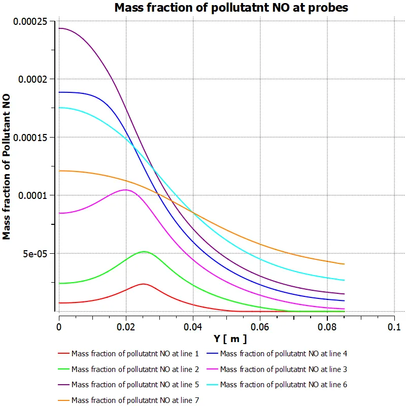
Mass fraction of pollutant NOx
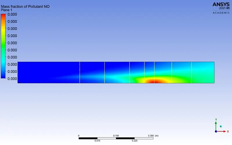
Mass fracton of pollutant NOx along the above line probes
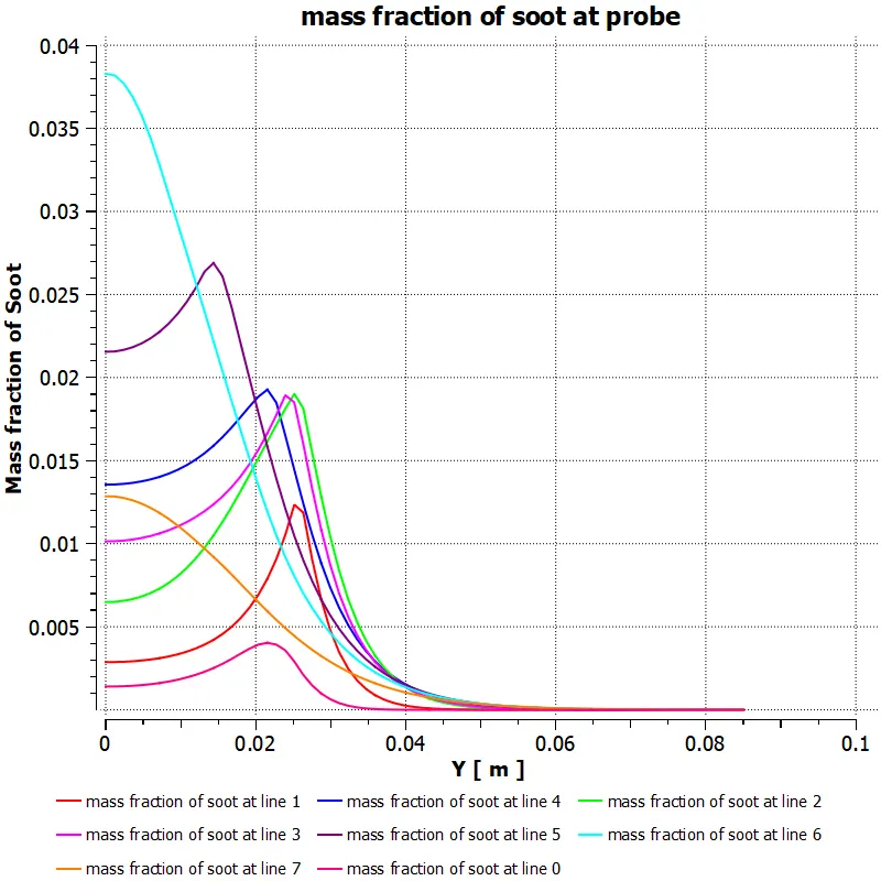
Mass fraction of soot
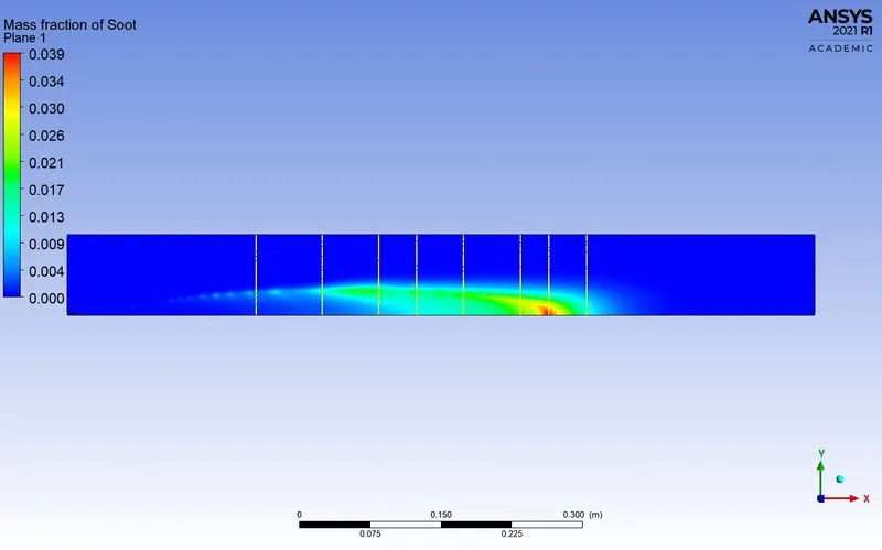
Mass fracton of soot along the above line probes
Case 4: ch4=0.75 and h2o=0.25
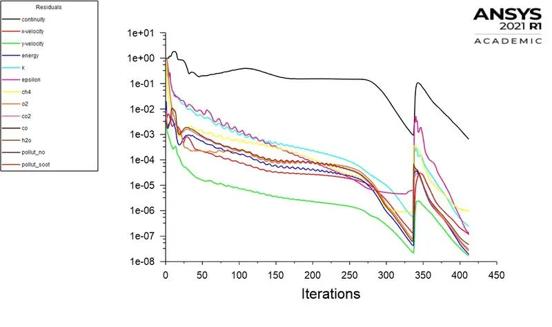
Residuals
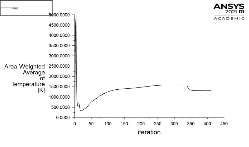
Area-weighted Avergae temperature:
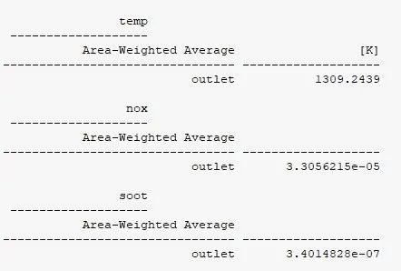
Area-Weighted Average of mass fraction of Pollutant NOX
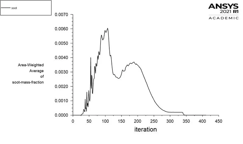
Area-Weighted Average of mass fraction of soot
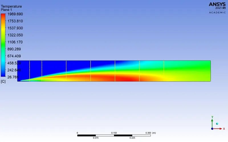
Temperature contour
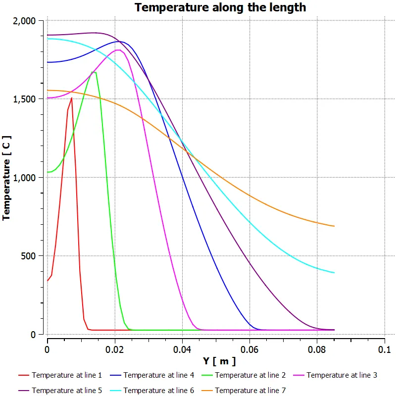
temperature along the probes
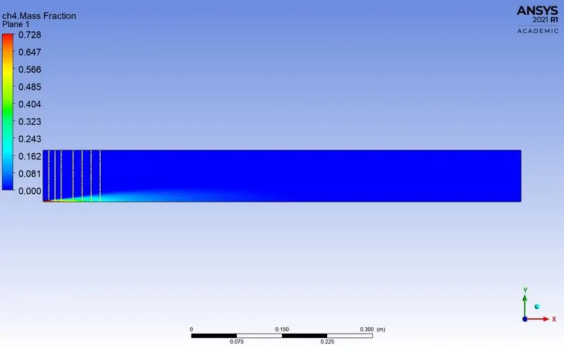
Mass fraction of ch4
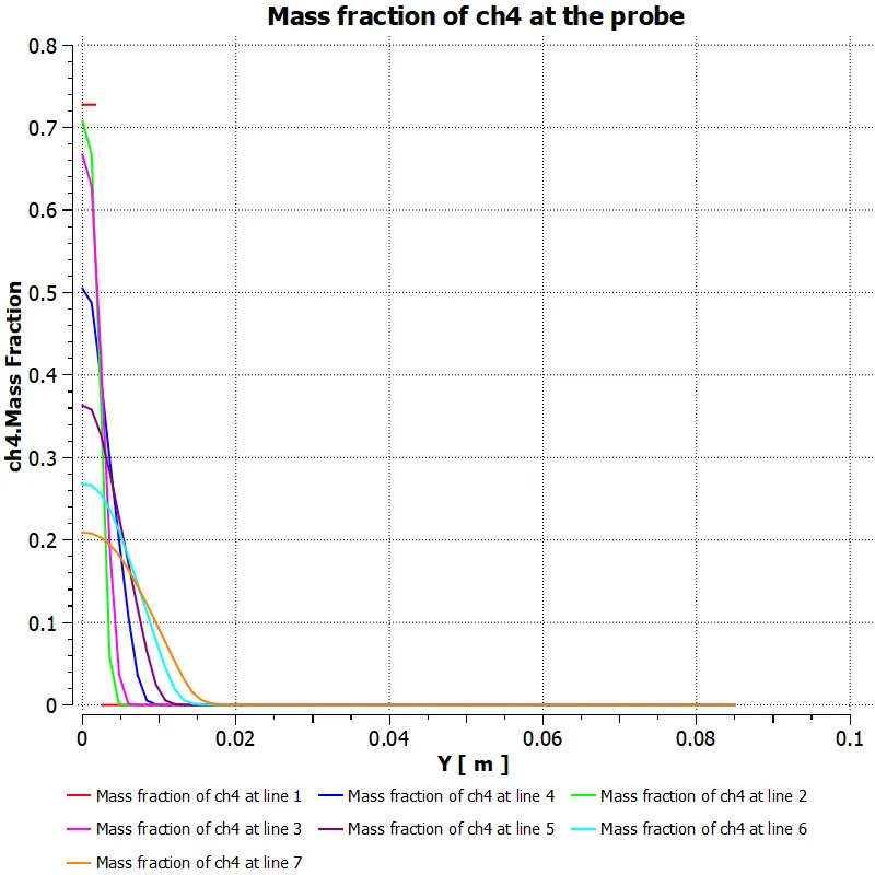
Mass fracton of ch4 along the above line probes
Mass fraction of co
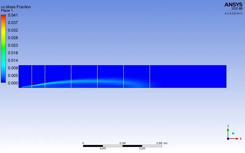
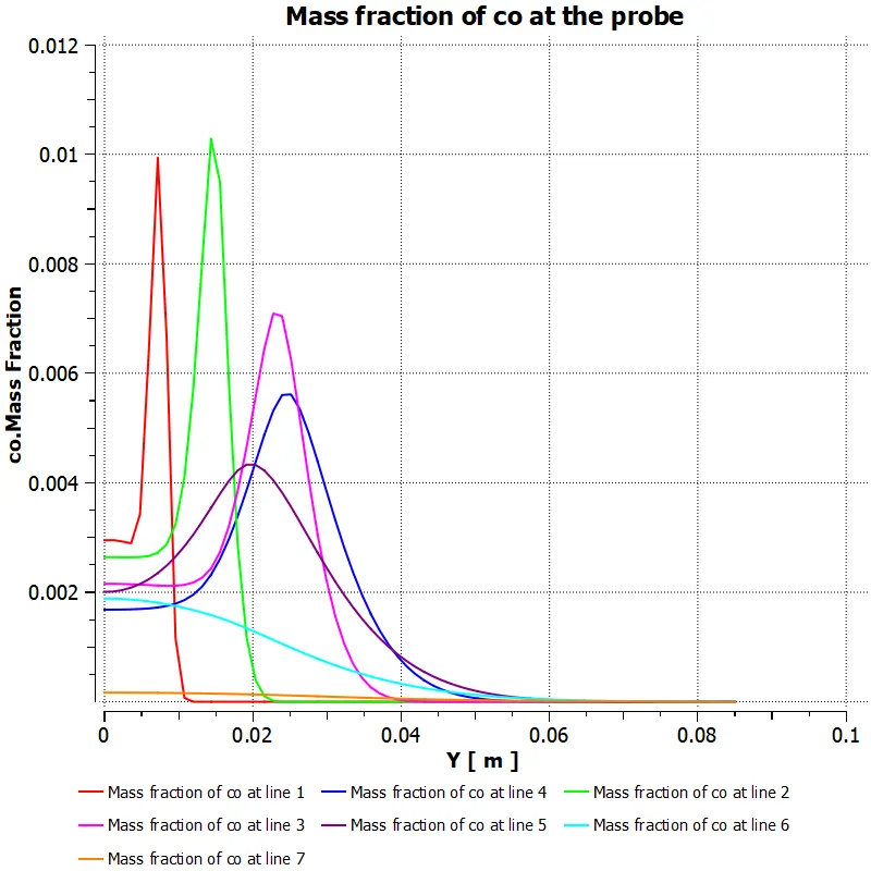
Mass fracton of co along the above line probes
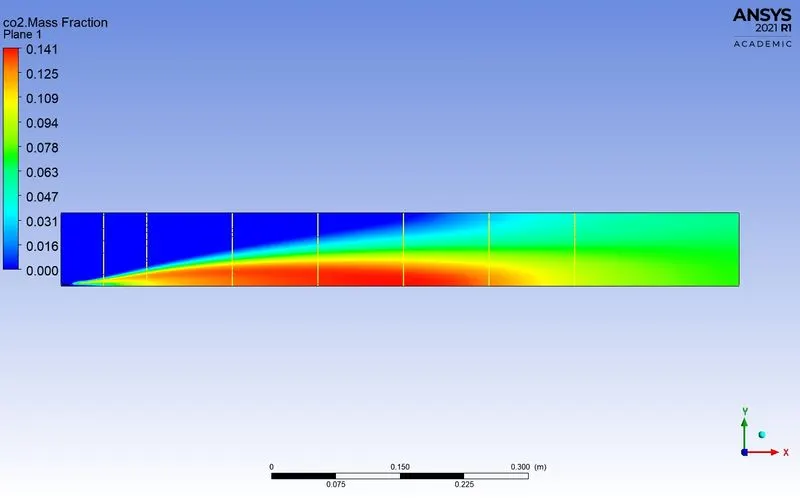
Mass fraction of co2
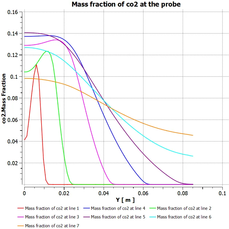
Mass fracton of co2 along the above line probes
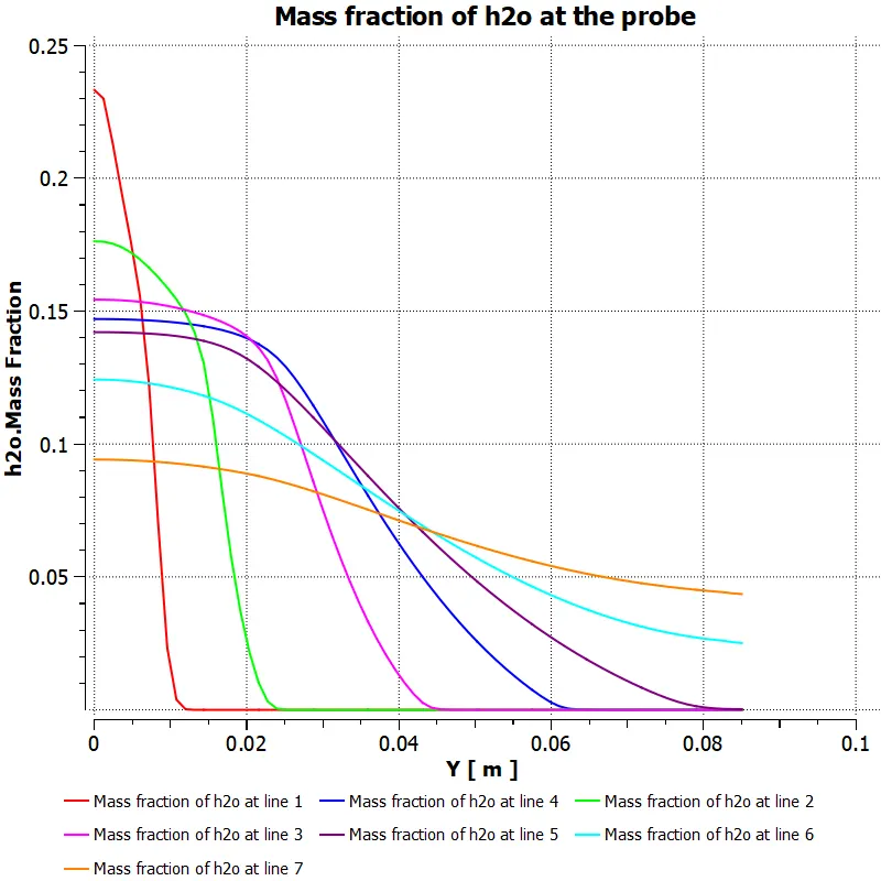
Mass fraction of h2o
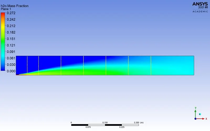
Mass fracton of h2o along the above line probes
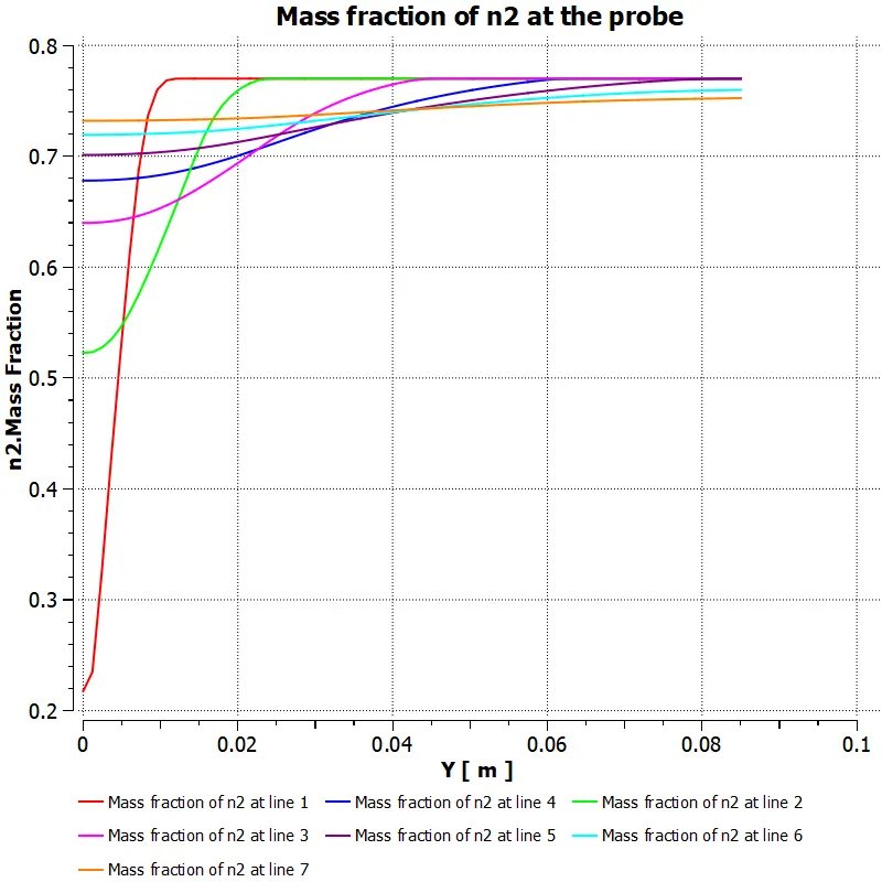
Mass fraction of n2
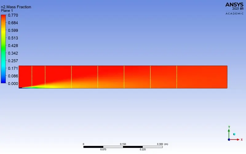
Mass fracton of n2 along the above line probes
Mass fraction of o2
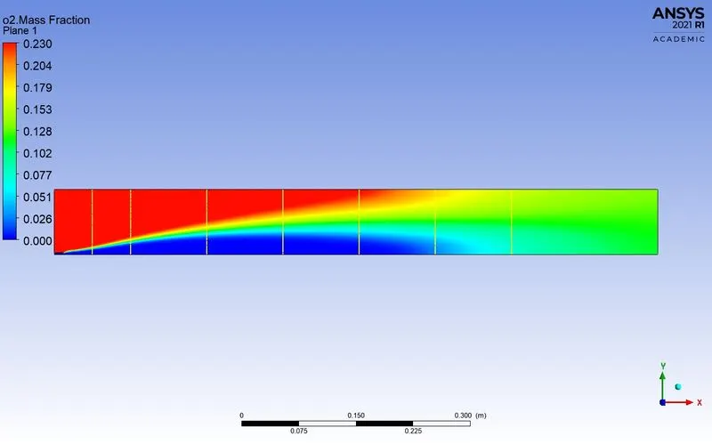
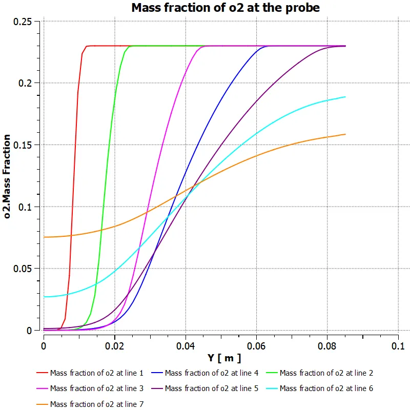
Mass fracton of o2 along the above line probes
Mass fraction of pollutant NOx
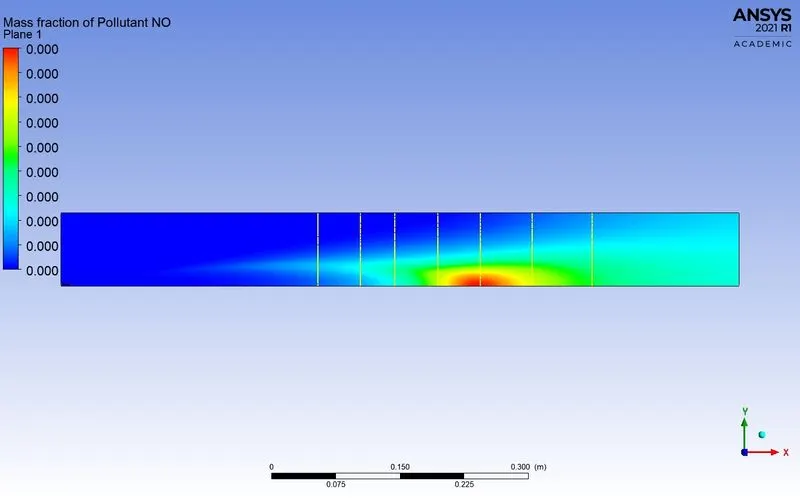
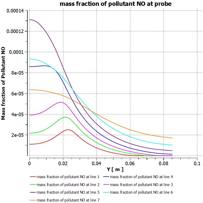
Mass fracton of pollutant NOx along the above line probes
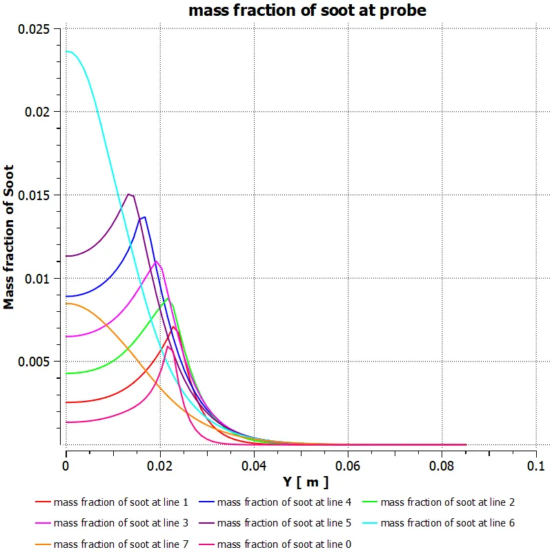
Mass fraction of soot
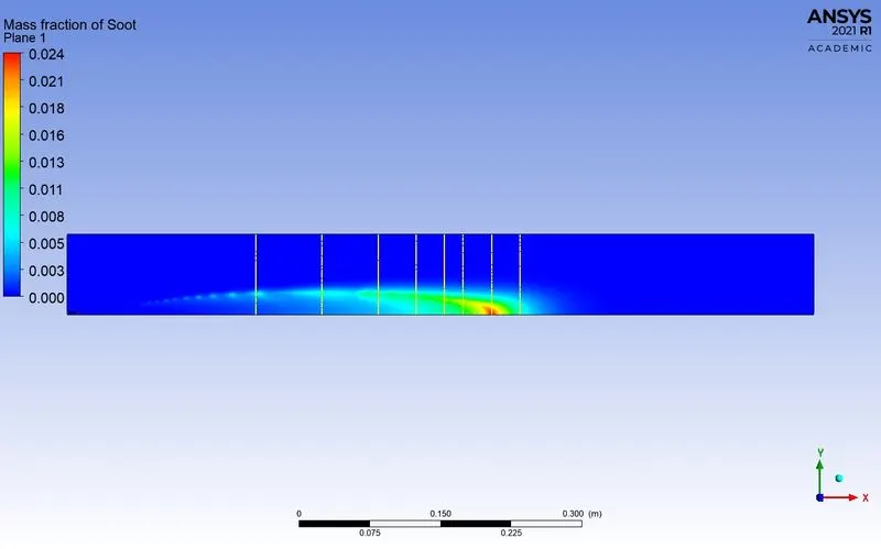
Mass fracton of soot along the above line probes
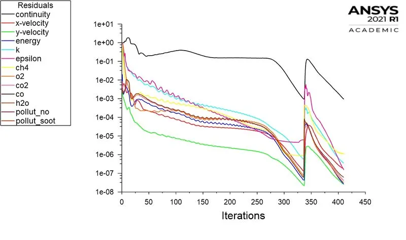
Case 5: ch4=0.7 and h2o=0.3
Residuals
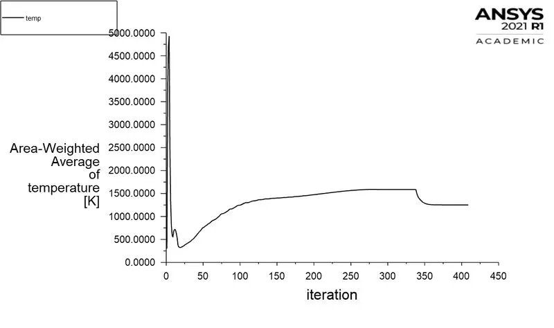
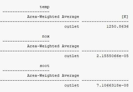
Area-weighted Avergae temperature:
Area-Weighted Average of mass fraction of Pollutant NOX
Area-Weighted Average of mass fraction of soot
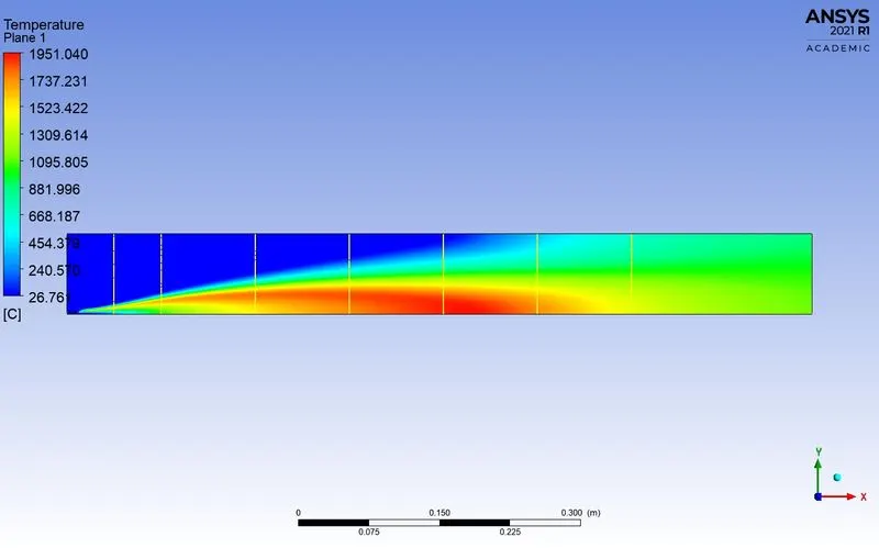
Temperature contour
temperature along the probes
Mass fraction of ch4
Mass fracton of ch4 along the above line probes
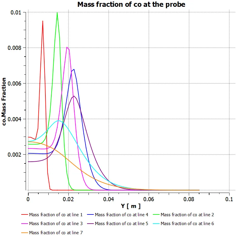
Mass fraction of co
Mass fracton of co along the above line probes
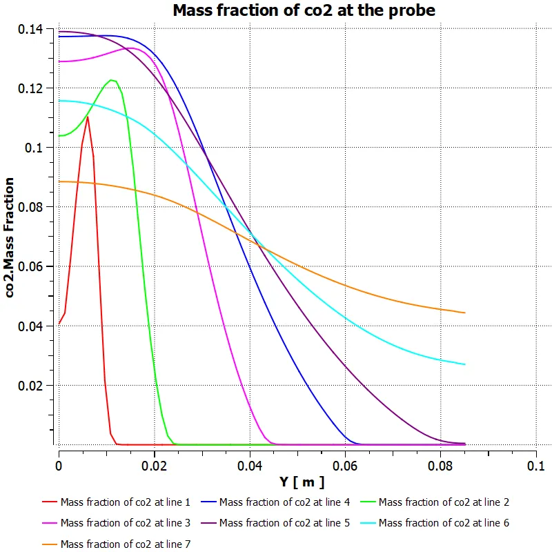
Mass fraction of co2
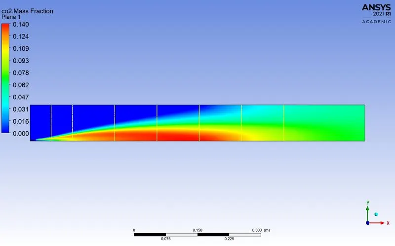
Mass fracton of co2 along the above line probes
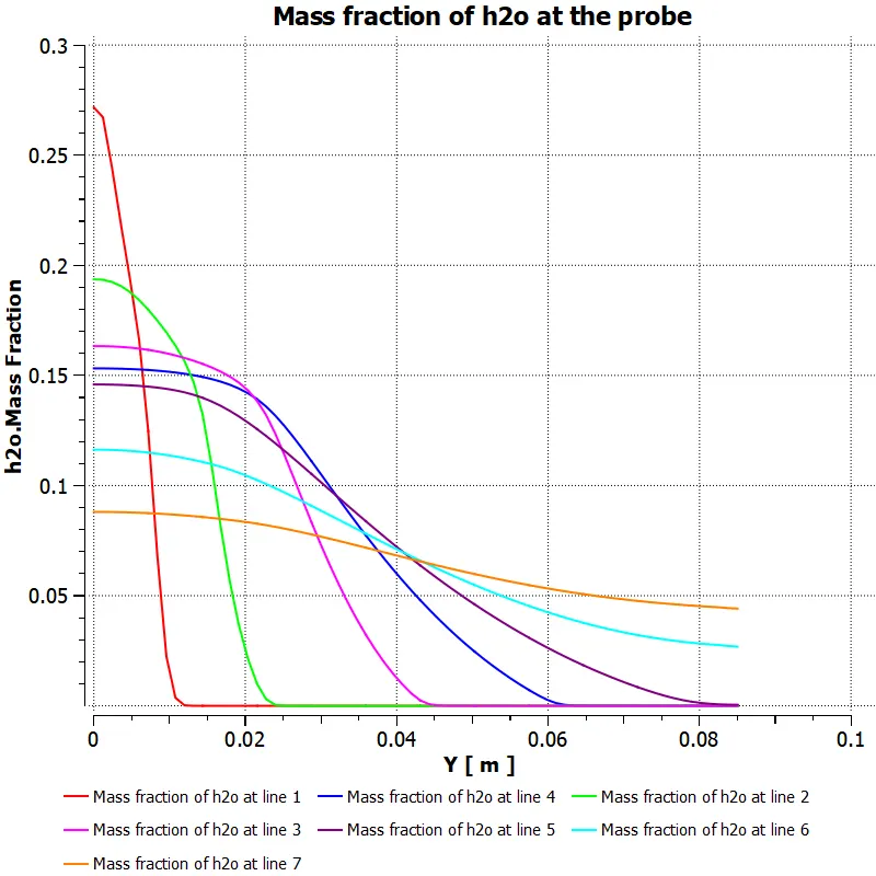
Mass fraction of h2o
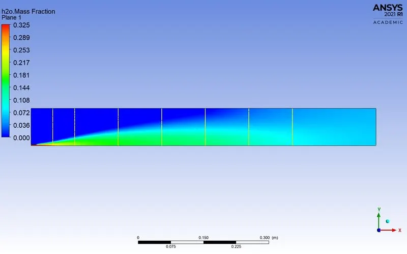
Mass fracton of h2o along the above line probes
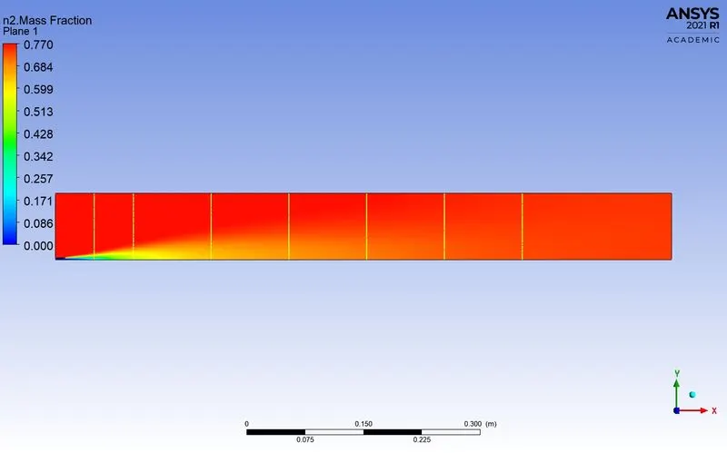
Mass fraction of n2
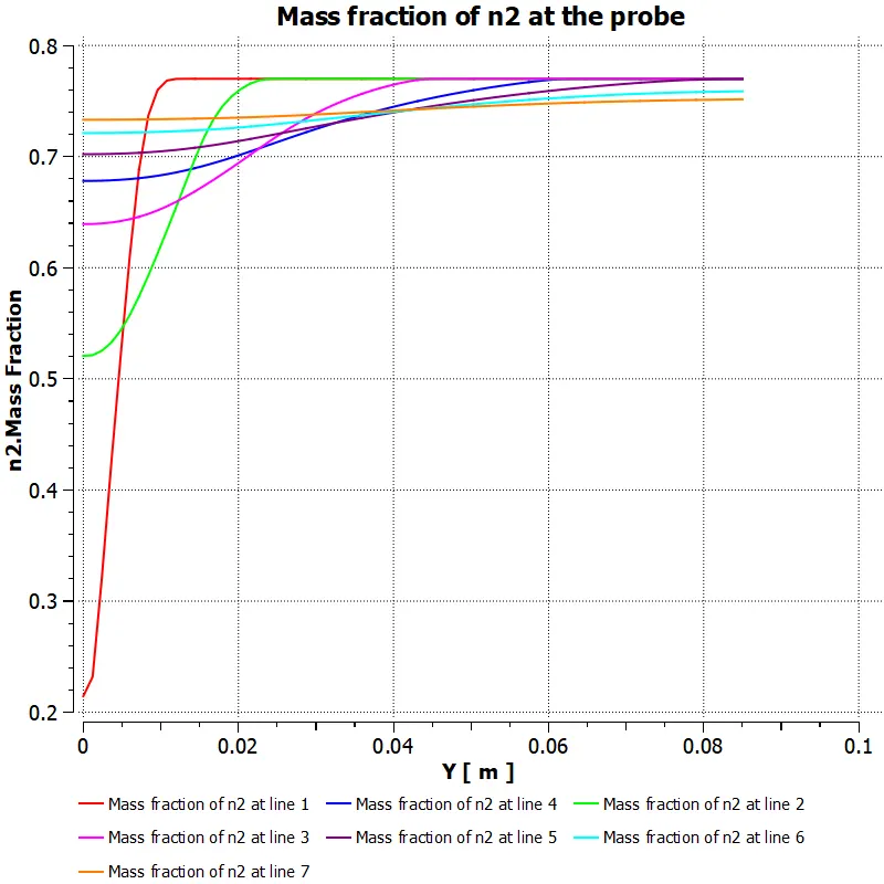
Mass fracton of n2 along the above line probes
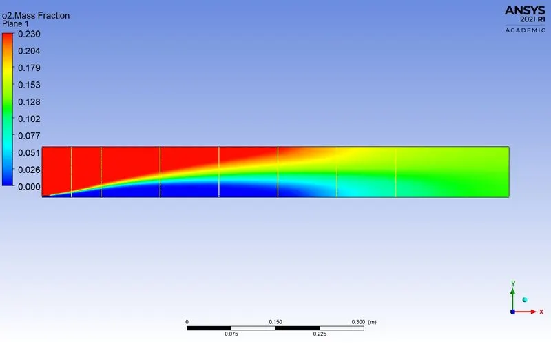
Mass fraction of o2
Mass fracton of o2 along the above line probes
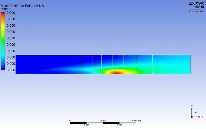
Mass fraction of pollutant NOx
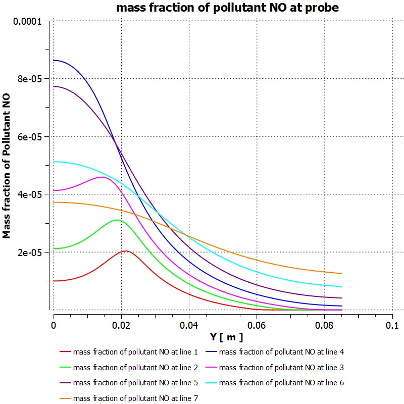
Mass fracton of pollutant NOx along the above line probes
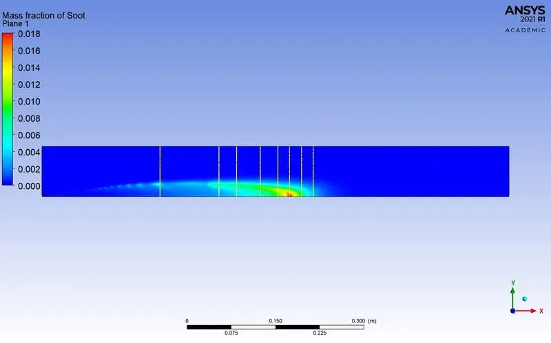
Mass fraction of soot
Mass fracton of soot along the above line probes
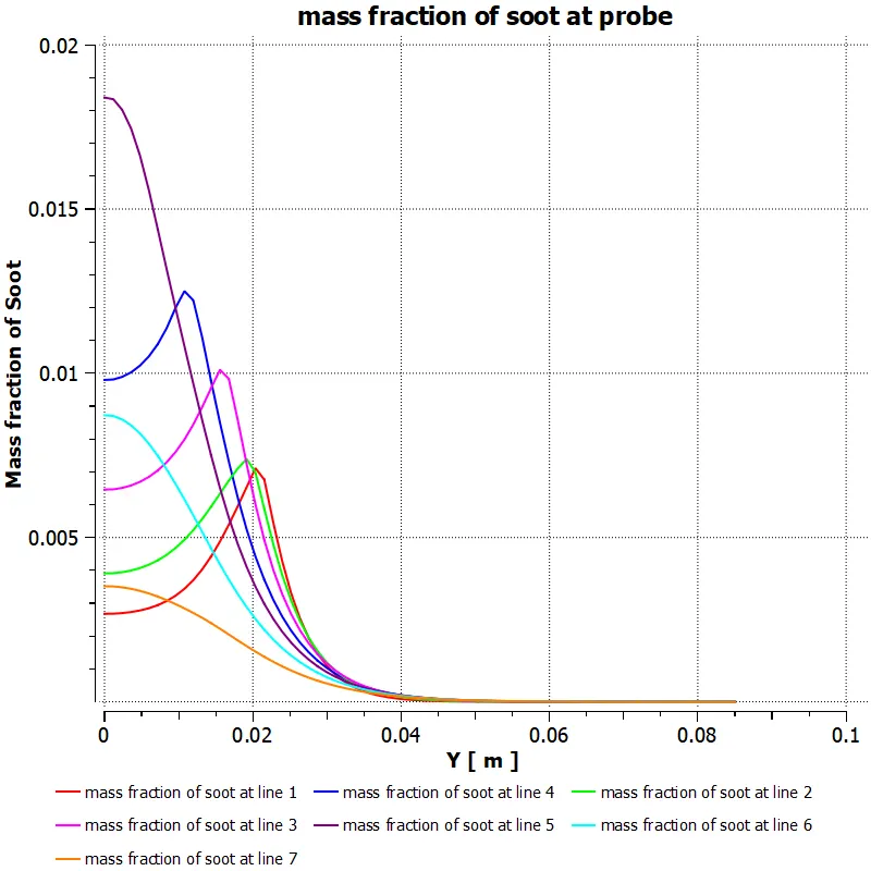
Table of parametric study
CONCLUSIONS
- With the increment in amount of water in fuel, the mass fraction of pollutant No & soot both decreases. It has been widely reported in literature that reduction in No is because of thermal effect. The mechanism behind the reduction of soot are not well understood. The water could reduce soot formation via physical, chemical or thermal effect.
- Supplying water into the combustion chambers of diesel engines is a widely used method to reduce the harmful gases from exhaust. Various systems which are being studied for making fuel water mixture are: - continuous water injection into the scavenging air, humid air motor, direct water injection, fuel water emulsion supply system using emulsifiers etc.
- From the present simulation it has also been observed that flame temperature decreases significantly with increase in water percentage. The lower flame temperatures consequent to water addition decrease the rate of fuel pyrolysis and carbon formation. The accompanying lower NO x emissions can also be attributed to decreased flame temperatures as the reaction mechanism responsible for their formation (Zeldovich mechanism) is highly temperature sensitive.