Week 10 - Simulating Combustion of Natural Gas.
Battery Thermal Management Systems: Design Approach of Cooling Technologies.
Problem Statement:
Perform the heat transfer analysis using ANSYS-Fluent software for the cylindrical Lithium-ion Battery with heat generation boundary conditions. Create an enclosure and use air as the working fluid for cooling the battery back system (4 x 2). Take air inlet temperature as 300 K.
Expected results:
- Explain why battery cooling is needed. And give a brief description of various techniques for battery cooling.
- Run the simulation by varying the velocity from 1m/sec to 5m/sec for at least 3 velocities and discuss the results.
- Find out the maximum temperature and heat transfer coefficient obtained by the battery.
- Prove that the simulation has achieved convergence with appropriate images and plots.
- Identify potential hotspots on the model.
Property of the Lithium-ion Battery
Density = 2700 kg/m^3
Specific heat = 900 J/kg.K
Thermal Conductivity = 7.14 W/m.K
Heat Generation per battery = 10 W
Size of the Battery = 18 mm diameter and 65 mm height.
We need to calculate the power density as a Volumetric heat source for each cell. the calculation is shown below.
Formulas:
The volume of Each Cell = (pi/4)*L*D^2
Heat Generation per battery = 10 W
Energy = Heat Generation per battery/Volume
Calculation:
Diameter: 0.018 m
Length: 0.065 m
Energy: 10 W
The volume of Each Cell = (pi/4)*L*D^2
hence Volume= 1.65E-05 m^3
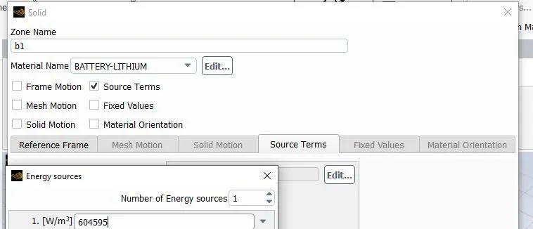
Energy: 604595 W/m^3
Introduction:
Electric vehicle and hybrid electric vehicle (EV/HEV) technology, as a green substitute for conventional combustion vehicles, has attracted a significant amount of attention globally and is quickly replacing internal combustion engine-powered vehicles.
The performance of EVs and HEVs is highly dependent on battery capacity. Battery thermal management systems (BTMS’) are developed to monitor and optimize the thermal status of batteries. The battery temperature is a critical factor for battery operating performance. Specifically, the charge/discharge capacity can be strongly influenced by temperature. This availability will further impact the performance of applications. For instance, the discharge rate will determine the acceleration process of electric and hybrid electric vehicles. The lifespan of batteries also greatly depends on the operating temperature. Under normal operating conditions, of say −30 °C to 60 °C, the battery health varies significantly from the optimal battery temperature range.
Efficient temperature management systems contribute significantly to battery health and extend the overall lifespan. Moreover, as the capacity and charge/discharge rate increase, battery security issues need more attention. Subsequently, various BTMSs’ has been developed to meet the demand for higher power, faster charge rates, and improved driving performance. Modern BTMSs’ are divided into two groups: active systems and passive systems. Passive BTMS generally employ phase change materials, heat pipes, and hydrogels. Zero extra power consumption is the most prominent feature of these systems. However, the cooling process is difficult to manage. Conversely, traditional active methods generally lead to forced circulation and circulation of specific cooling materials and substances such as water and air. The main issue is that the cooling effect can be very limited under certain circumstances. Thermoelectric power generation devices for vehicles have been developed for years. In contrast, thermoelectric coolers (TEC) which are employed by battery thermal management are a comparatively new candidate for electric vehicles. These benefit from strong cooling capacities and reliable working potential and have attracted increasingly more attention for integration into BTMS.
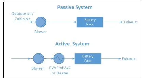
The battery thermal management system (BTMS) plays a vital role in the control of the battery's thermal behavior. The BTMS technologies are air cooling system, liquid cooling system, direct refrigerant cooling system, phase change material (PCM) cooling system, and thermo-electric cooling system as well as heating. These systems are analyzed through a trade-off between performance, weight, size, cost, reliability, safety, and energy consumption. According to the analysis two prime battery, thermal management systems are recommended: a combined liquid system (CLS) and a variant system with PCM.
The BTMS should have the following essential functions:
Cooling: Due to inefficiency, battery cells will not only generate electricity but also heat. This heat should be moved from the battery pack when the battery temperature reaches the optimum temperature or even in advance. Thus, a cooling function is required in BTMS
Heating: In cold climates, battery pack temperature probably falls below the lower temperature limit. Hence, a heating function, such as a PTC heater, is required to assist the battery pack to reach the proper temperature range in a shorter time.
Insulation: In extreme cold or hot weather, the temperature difference between the inside and outside of the battery pack is much larger than that in mild weather. Battery temperature will thus fall (cold) or rise (hot) sooner out of the proper temperature range. To prevent this, good insulation can slow down the falling or rise of battery temperature, especially when the vehicle is parked outdoors.
Ventilation: Ventilation is required to exhaust the hazardous gases within the battery pack. In some systems, such as air systems, this function is combined with cooling and heating functions.
Thermal Issues with Lithium Iron Battery:
Lithium-ion cells' performance depends on both the temperature and the operating voltage. Lithium-Ion cells work well when cells operate within limited voltage and temperature. Otherwise, the damage will occur to the cells and will be irreversible. In over-voltage situations the charging voltage exceeds the bearable cell voltage, resulting in excessive current flows and at the same time, it causes two problems. At excessive currents the Lithium-ions are deposited more rapidly than intercalation to the anode layers, Lithium ions are then deposited on the surface of the anode as metallic Lithium. This is Lithium plating. It gives rise to the reduction in the free Lithium ions and an irreversible capacity loss.
There are two types of metallic lithium plating, namely homogeneous lithium plating and heterogeneous lithium plating, but lithium plating is dendritic in form. Eventually, it can result in a short circuit between the electrodes.
As with over-voltage, under-voltage also brings about problems that give rise to the breakdown of the electrode materials.
Chemical reaction rates have a linear relation to temperature. The decrease in the operating temperature will reduce the reaction rate and the capacity of carrying current during charging or discharging. In other words, the battery power capacity is decreased. Moreover, the reduction of reaction rate makes it harder to insert lithium ions into intercalation spaces. The result is the reduction of power and lithium plating causing capacity loss.
High temperature increases the reaction rate with higher power output, however, it also increases heat dissipation and generates even higher temperatures. Unless the heat is dissipated quicker than heat is generated, the temperature will be higher and finally, a thermal runaway will result.
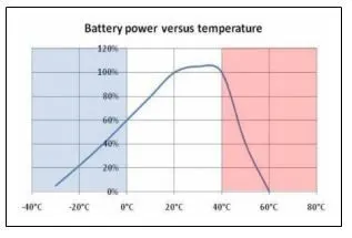
Thermal runaway consists of several stages and each stage will give rise to more irreversible damage to cells. First, the SEI layer is dissolved into electrolytes at around 80ºC. The primary overheating may result from excessive current or high ambient temperature. After the breakdown of the SEI layer, the electrolyte begins to react with the anode. This reaction is exo-thermal which drives the temperature higher. Secondly, the higher temperature causes the organic solvents to break down with the release of hydrocarbon gases. Normally this starts at around 110 ºC. The pressure inside cells is built up by the gas and the temperature is beyond the flashpoint. However, the gas does not burn due to the lack of oxygen. A vent is needed to release the gas in order to keep cells under proper pressure and avoid a possible rupture. Then, the separator is melted, and short circuits occur between the anode and cathode at 135 ºC. Finally, the metal oxide cathode breaks down at 200 ºC and releases oxygen which allows the electrolyte and hydrogen gas to burn. This reaction is also exo-thermal and drives temperature and pressure still further.
The importance of a cooling system
While advancements have been made in electric vehicles batteries that allow them to deliver more power and require less frequent changes, one of the biggest challenges that remain for battery safety is the ability to design an effective cooling system.
Batteries work based on the principle of voltage differential and at high temperature, the electron inside becomes excited which deserves the difference in voltage between the two sides of the battery. Because batteries are only manufactured to work between certain temperature extremes, they will stop working if there is no cooling system to keep it in working range.
If there is a larger internal temperature difference it can lead to different charge and discharge rates for each cell and deteriorate the battery pack performance. potential thermal stability issues such as capacity degradation, thermal runaway, and fire explosion could occur if the battery overheats or if there is nonuniform temperature distribution in the battery pack. In the face of life-threatening safety issues, innovation is continually happening in the electric vehicle industry to improve the battery cooling system.
Types of Cooling System
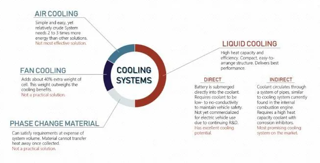
Phase change material absorbs heat energy by changing state from solid to liquid. While changing phase, the material can absorb large amounts of heat with little change in temperature. Phase change material cooling systems can meet the cooling requirements of the battery pack, however, the volume change that occurs during a phase change restricts its application. Also, phase change material can only absorb heat generated, not transfer it away, which means that it won’t be able to reduce overall temperature as well as other systems. Although not favorable for use in vehicles, phase change materials can be useful for improving thermal performance in buildings by reducing internal temperature fluctuations and reducing peak cooling loads.
Cooling fins increase surface area to increase the rate of heat transfer. Heat is transferred from the battery pack to the fin through conduction, and from the fin to the air through convection. Fins have high thermal conductivity and can achieve cooling goals, but they add a lot of additional weight to the pack. The use of fins has found a lot of success in electronics, and traditionally they have been used as an additional cooling system on internal combustion engine vehicles. Using fins to cool the electric car battery has fallen out of favor since the additional weight of the fins outweighs the cooling benefits.
Air cooling uses the principle of convection to transfer heat away from the battery pack. As air runs over the surface, it will carry away the heat emitted by the pack. Air cooling is simple and easy, but not very efficient and relatively crude compared to liquid cooling. Air cooling is used in earlier versions of electric cars, such as the Nissan Leaf. As electric cars are now being used more commonly, safety issues have arisen with purely air-cooled battery packs, particularly in hot climates. Other car manufacturers, such as Tesla, insist that liquid cooling is the safest method.
Liquid coolants have higher heat conductivity and heat capacity (ability to store heat in the form of energy in its bonds) than air, and therefore performs very effectively and own advantages like compact structure and ease of arrangement. Out of these options, liquid coolants will deliver the best performance for maintaining a battery pack in the correct temperature range and uniformity. Liquid cooling systems have their own share of safety issues related to leaking and disposal, as glycol can be dangerous for the environment if handled improperly. These systems are currently used by Tesla, Jaguar, and BMW, to name a few.
Geometry
Prepare Geometry in SpaceClaim.
Firstly, the fluid flow fluent was dragged into the main operating window, then the space claim was opened, and after that, a sketch was created on the X-Z plane (x-z horizontal axis) (y- vertical axis).
The circle was created on the sketching module with 18 mm diameter dimension and the surface was created from that sketch, And surface was extracted from that sketch.
Now for these eight surfaces, we have to share topology so that we can generate a conformal mesh, in the meshing module.
A Enclosure has to be created around the batteries, there are multiple methods to achieve this, but the easiest is using the enclosure tool in ANSYS to generate the tunnel. The inlet of the enclosure is 10 mm from the front of the batteries, the outlet is 10 mm from the back of the body. The height of the enclosure is 10 mm above batteries and the width is 10 mm from the side of the batteries and the bottom is 10 mm. The enclosure is checked for Interference and it is repaired as well.
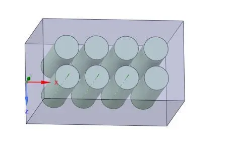
Open SpaceClaim--Select Plane--Draw 8 Circles one by one and then give dimensions as well.
Diameter of circle = 18 mm
The gap between two circles = 4 mm
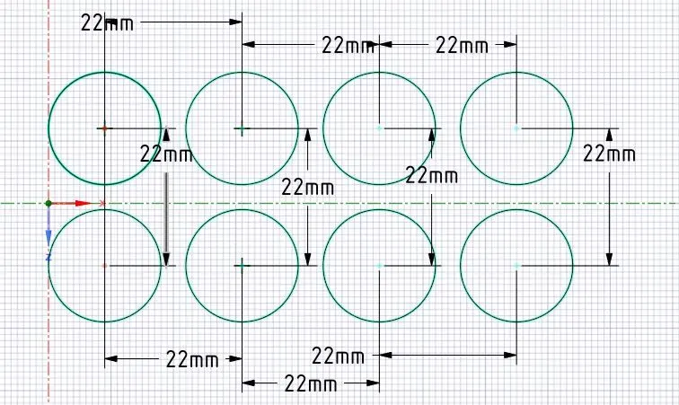
Then pull the circle up to 65mm in height by using the PULL tool.
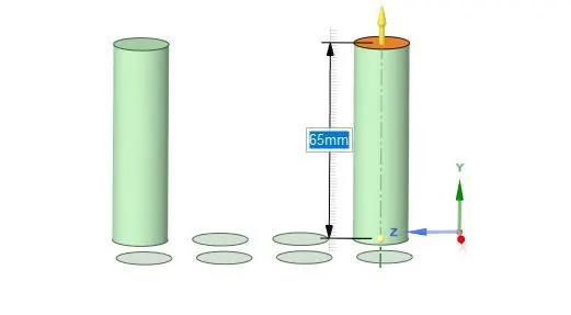
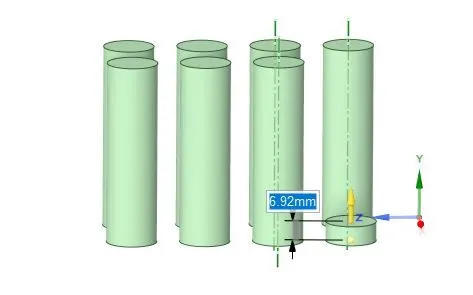
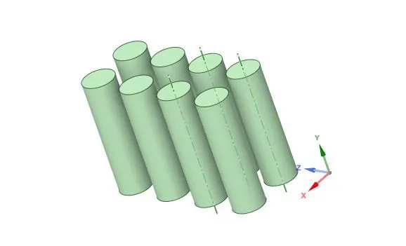
Now with the help of the Enclosure tool, enclose all the batteries and create a battery pack system.
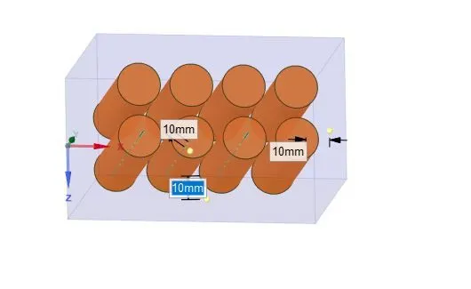
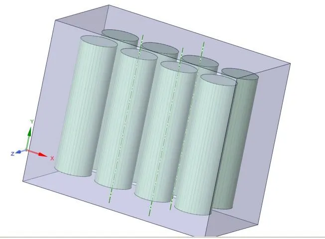
The given problem is external flow over battery simulation. A Enclosure is created over Batteries using the 'Enclosure' option in Spaceclaim. While creating the enclosures, the 'Interference' option was used to remove any geometric interference and common regions created by the double enclosures. The 'topology' option is set to 'Share' to ensure data is shared between different enclosures.
Mesh
Set Preference as CFD in the details of mesh and Element size as 5 mm. In meshing, we mesh the geometry by Defining the sizes of the different elements. Where the fluid volume and cells mesh differently as shown below due to the type of system.
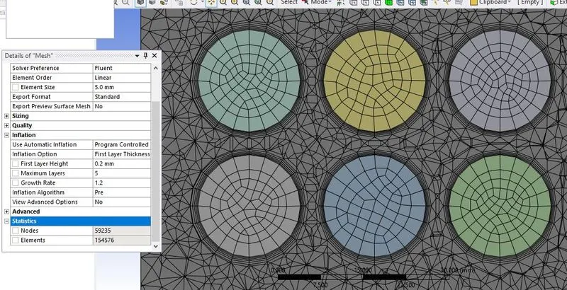
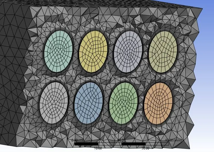
To capture the near-wall physics accurately, a Mesh inflation is provided to the geometry. To come up with the right mesh size, the following calculations are done. Shown below is the mesh obtained.
The mesh inflation option is set to 'first layer thickness. Two parameters are required: The first layer thickness of inflation and the number of inflation layers. Firstly, the boundary layer thickness at the end of the battery is calculated using the boundary layer formula for turbulent flow over a body. Considering the y+ for the problem as 5, the first layer thickness is calculated.
Y+ Concept:
The behavior of the flow near the wall is a complicated phenomenon and to distinguish the different regions near the wall the concept of wall Y+ has been formulated. Thus Y+ is a dimensionless quantity and the distance from the wall is measured in terms of viscous lengths.
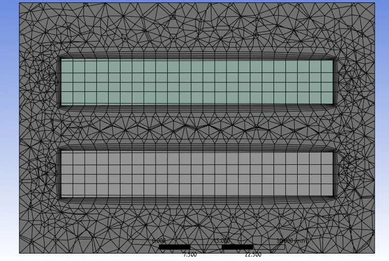
we are defining the name of the inlet and exit of the boundary and also naming each cell and fluid volume.
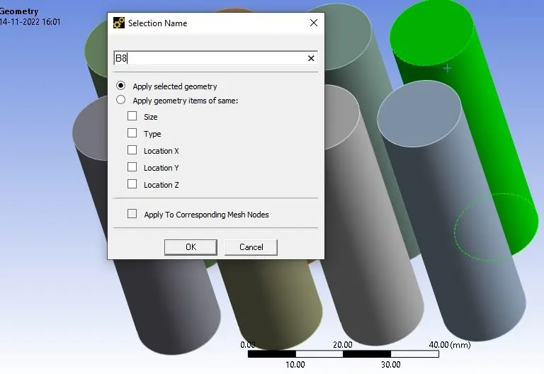
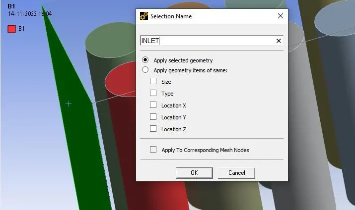
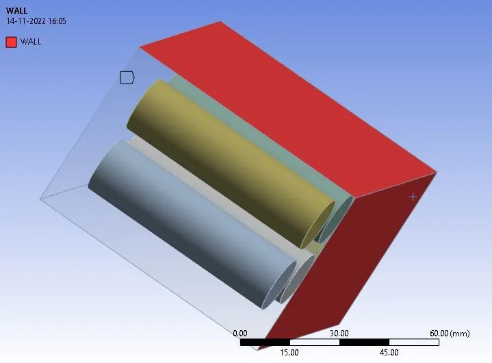
After the geometry preparation meshing was opened, here only meshing is an important parameter, and in this challenge, After meshing the fluent was opened, and the meshing was imported into the graphical window. Then I performed a mesh check operation.
Fluent Model setup:
In Ansys fluent we are taken, Pressure-based solver due to lower velocity. after defining the volumetric heat source parameter for each cell as a 604595 W/m^3. Also defining the inlet velocity parameter at the inlet boundary as 1, 3, and 5 m/s. using a k-epsilon method as a viscous model and standard method.
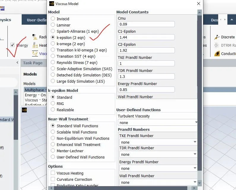
Next, Fluent is opened and a meshed check is performed. A pressure-based steady-solver is used for the case as the flow speed of 1, 3, and 5 m/s is well below Mach 0.3.
Time: Steady
Type: Pressure-based
Energy (on)
Turbulent Model: K-Epsilon
Inlet: velocity inlet
Outlet: pressure outlet
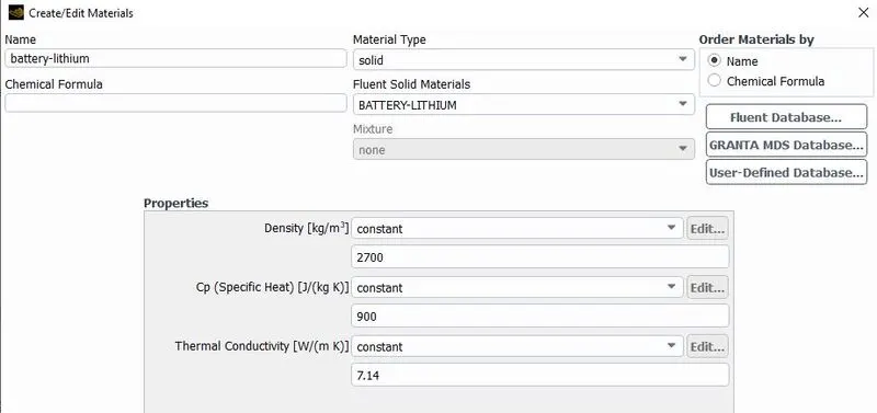
MATERIAL
Property of the Lithium-ion Battery
Density = 2700 kg/m^3
Specific heat = 900 J/kg.K
Thermal Conductivity = 7.14 W/m.K
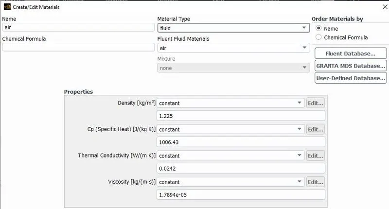
The existing MATERIAL's (air) properties were used
CELL ZONE
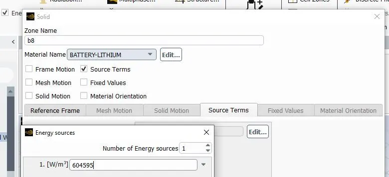
Boundary Conditions
Inlet Velocity
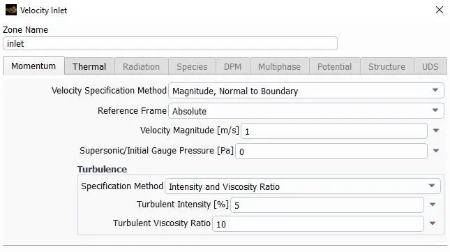
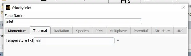
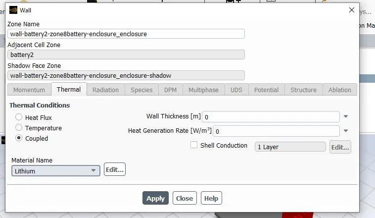
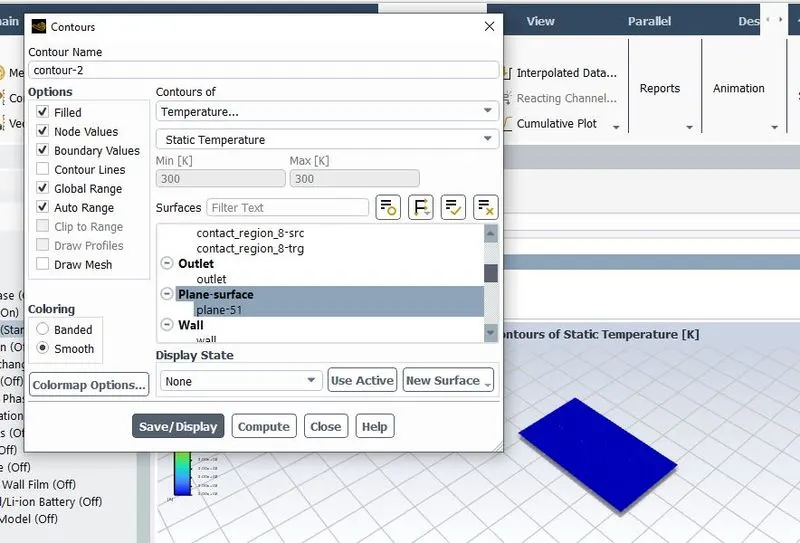
The problem is then initialized using the Hybrid solver. Create a surface plane to see the contours. Plots such as temperature contours, pressure contours, velocity contours, and vector plots are set up before the simulation. Finally, the case is run for 500 iterations.
Results
Inlet velocity = 1 m/s
Residual Plot
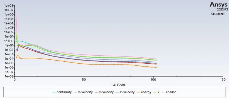
The number of iterations was set to 500.
But it is observed that the residuals have fallen below the specified tolerances and the solution attains convergence in ~105 iterations.
Temperature
Velocity
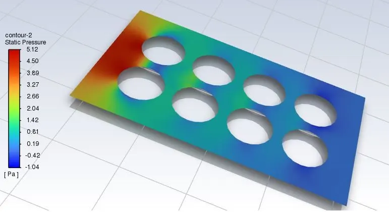
Pressure
Average Temperature
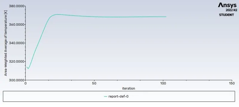
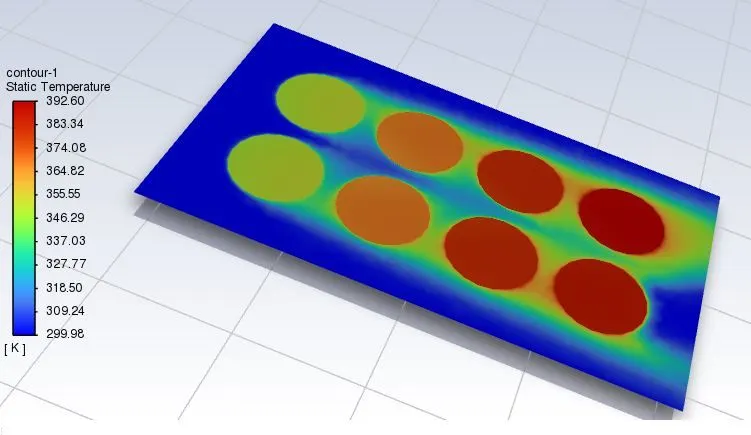
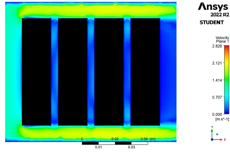
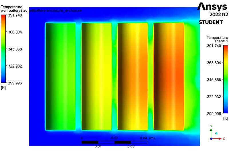
The Graph of Volume-Average of temperature shows the temperature 368 K for the inlet velocity 1 m/s and elements size of mesh is 5 mm.
Post Processing results
Vertical Pressure Plane
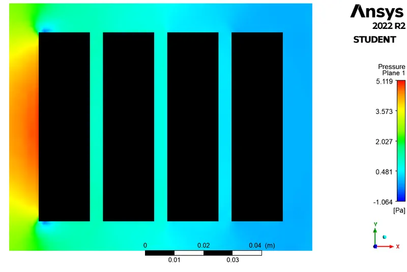
Horizental Pressure Plane
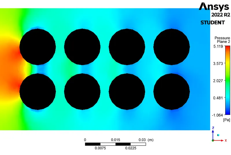
Vertical Velocity Plane
Horizental Velocity Plane
Vertical Temperature Plane
Horizental Temperature Plane
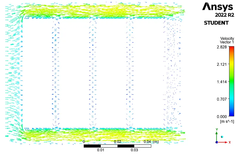
Velocity Vector in Vertical Plane
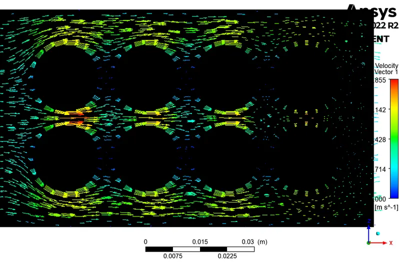
Velocity Vector in Horizental Plane
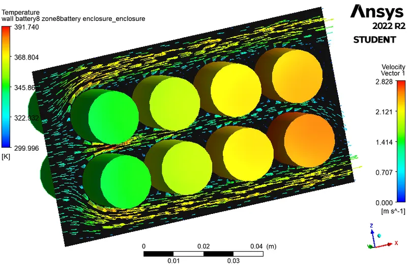
Velocity Vector in Horizental Plane and Temperature of Battery
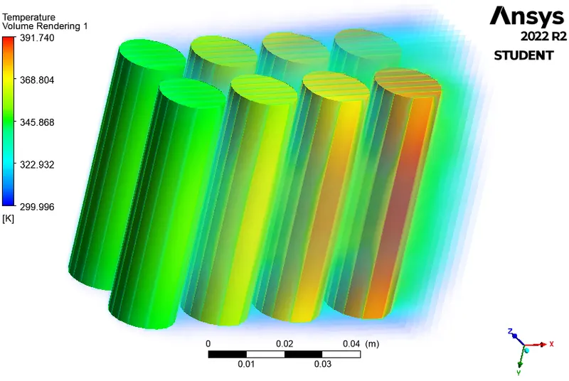
Volume Rendering of Temperature in Battery
Inlet velocity = 3 m/s
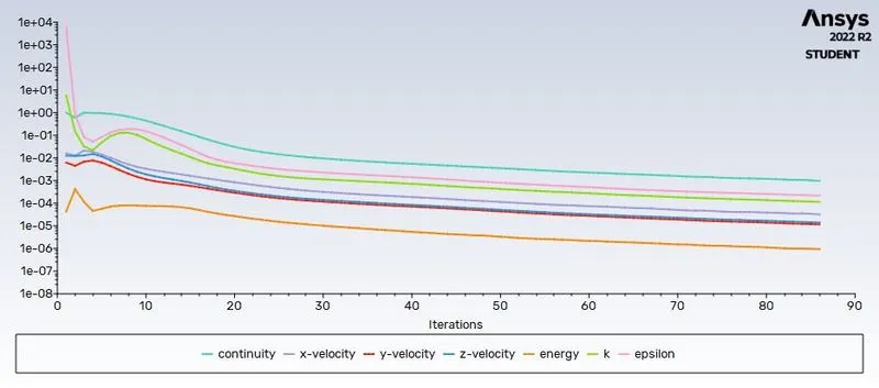
Residual Plot
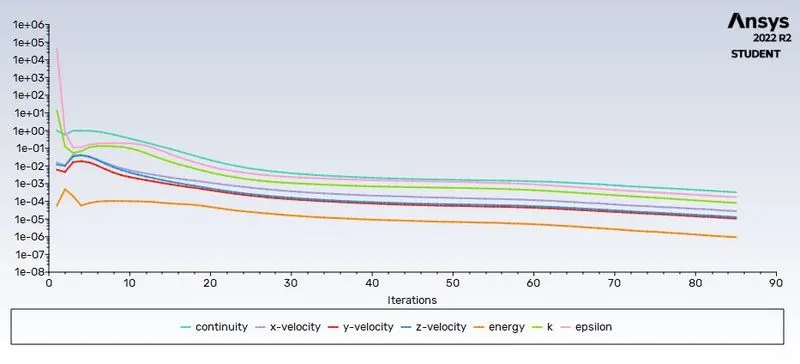
The number of iterations was set to 500.
But it is observed that the residuals have fallen below the specified tolerances and the solution attains convergence in ~85 iterations.
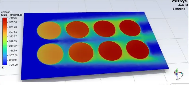
Temperature
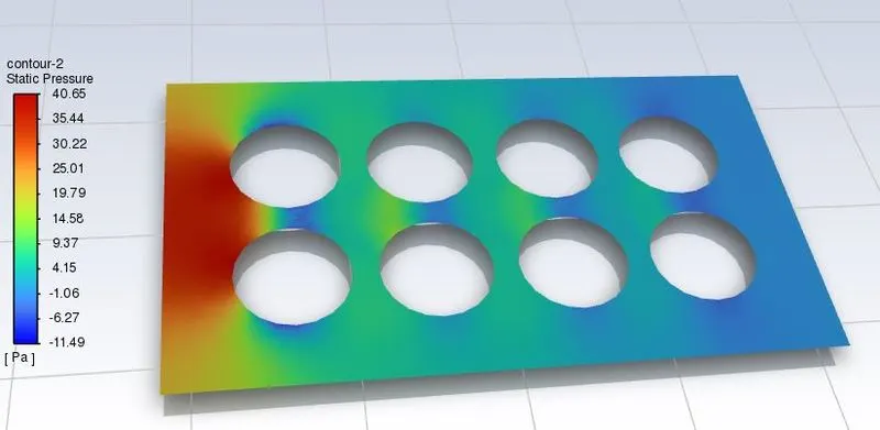
Pressure
Average Temperature
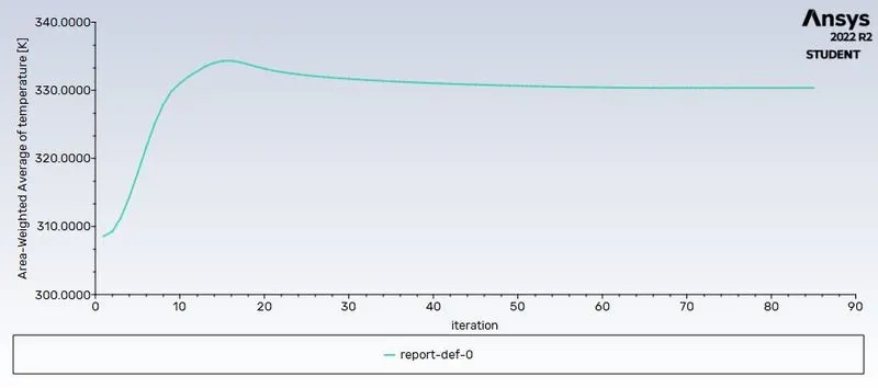
The Graph of Volume-Average of temperature shows the temperature 331 K for the inlet velocity 3 m/s and elements size of mesh is 5 mm.
Post Processing results
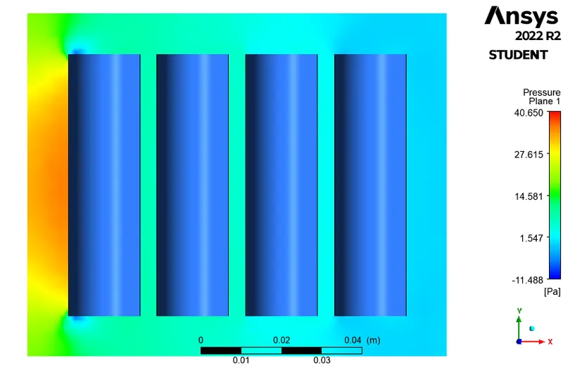
Vertical Pressure Plane with Battery
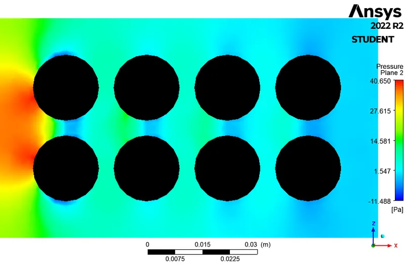
Horizental Pressure Plane
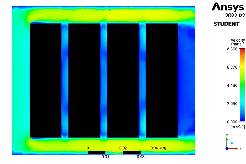
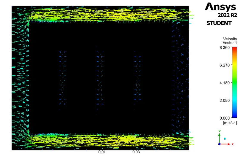
Vertical Velocity Plane
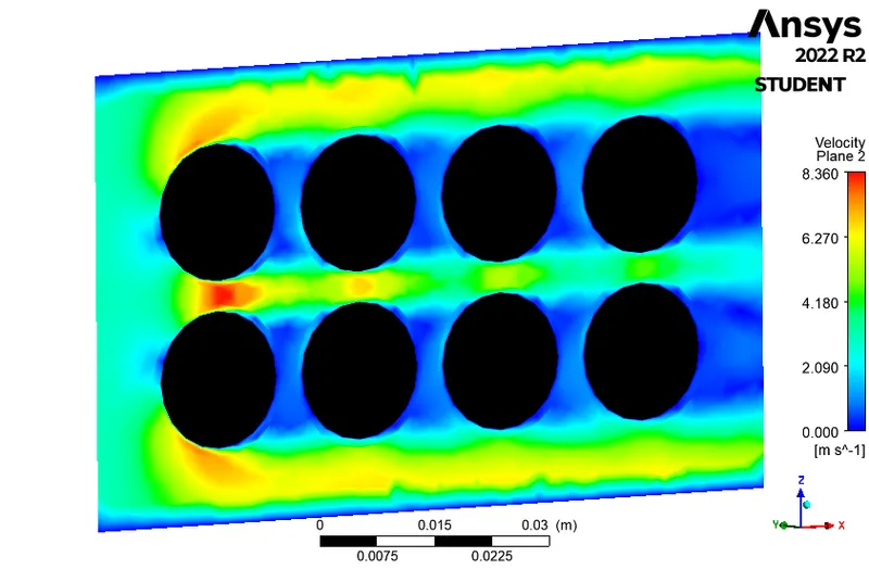
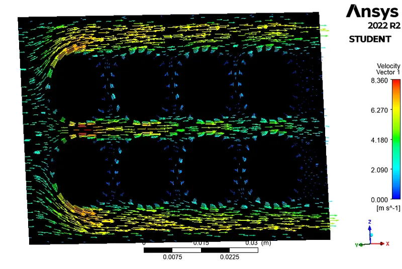
Horizental Velocity Plane
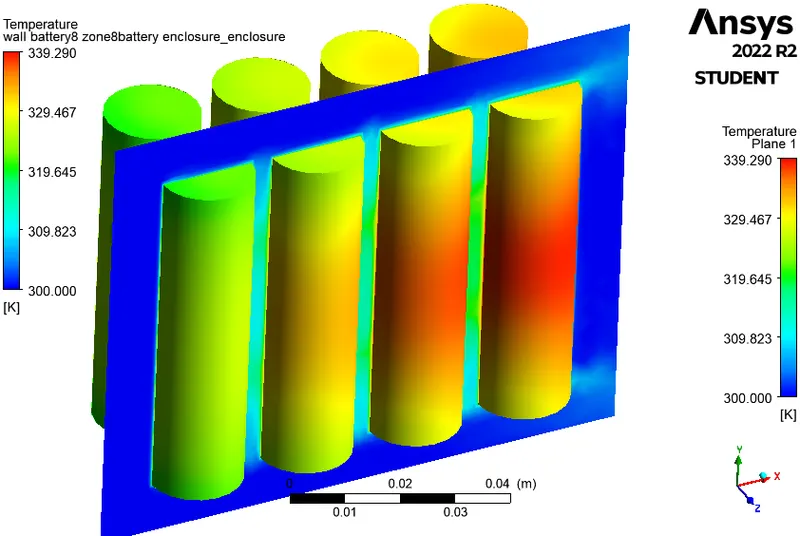
Vertical Temperature Plane with Battery Temperature
Velocity Vector in Vertical Plane
Velocity Vector in Horizental Plane
Velocity Vector in Horizental Plane and Temperature of Battery
Velocity Vector in Vertical Plane and Temperature of Battery
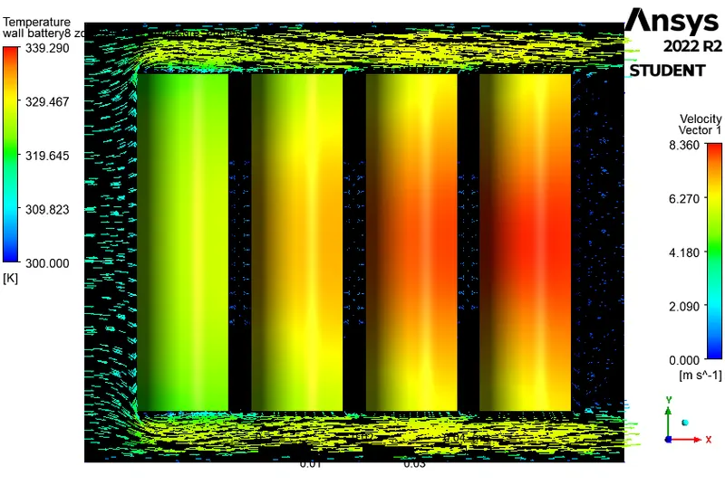
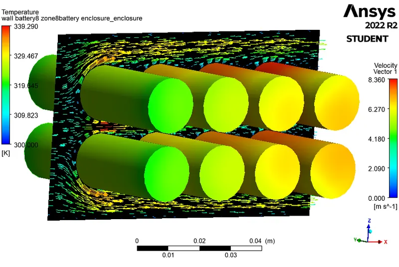
Velocity Vector in Horizental Plane and Temperature of Battery
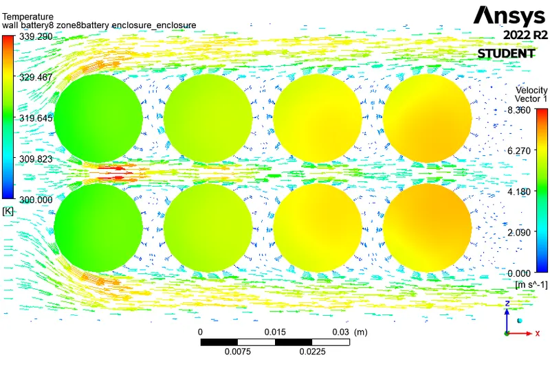
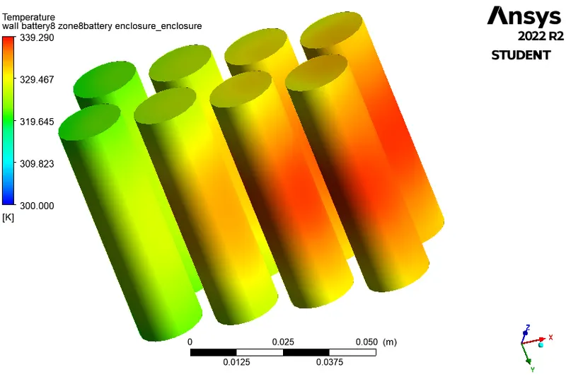
Temperature in Battery
Inlet velocity = 5 m/s
Residual Plot
The number of iterations was set to 500.
But it is observed that the residuals have fallen below the specified tolerances and the solution attains convergence in ~85 iterations.
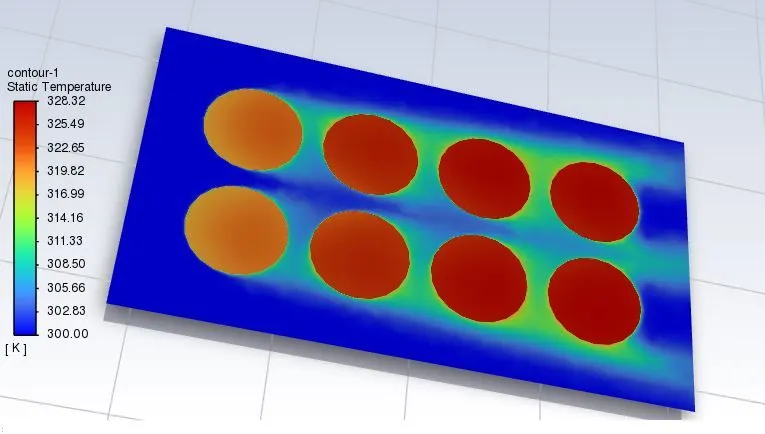
Temperature
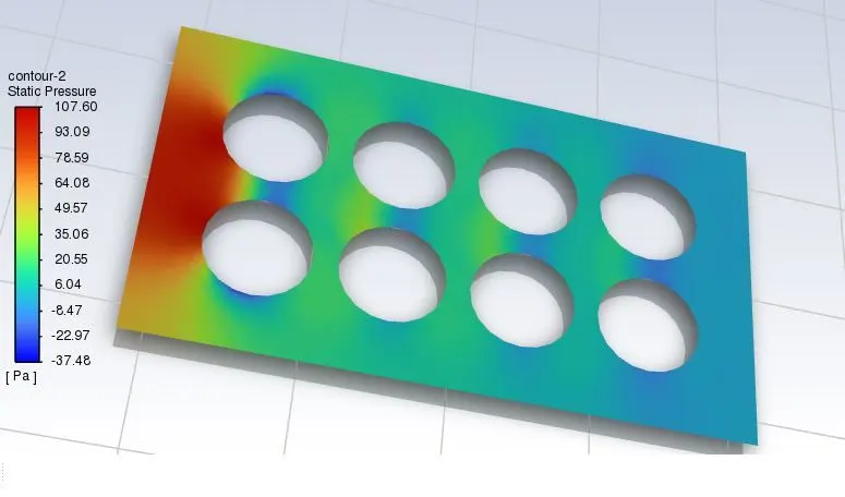
Pressure
Average Temperature
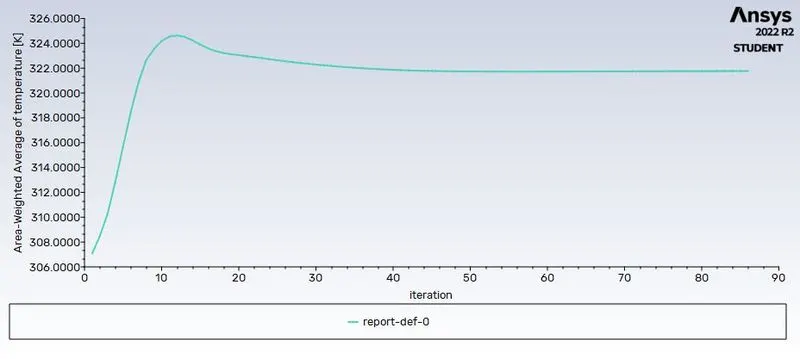
The Graph of Volume-Average of temperature shows the temperature 323 K for the inlet velocity 5 m/s & elements size of mesh is 5 mm.
Post Processing results
Vertical Pressure Plane with Battery
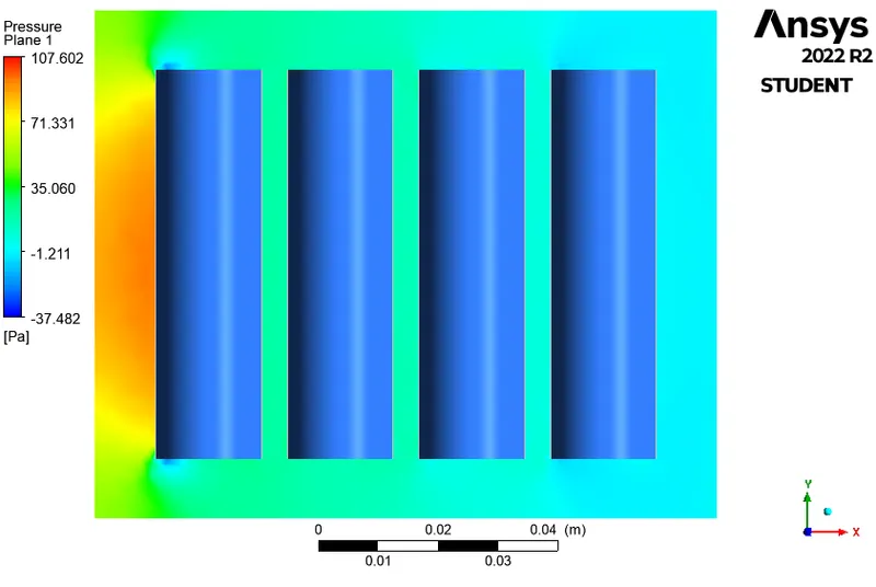
Horizental Pressure Plane
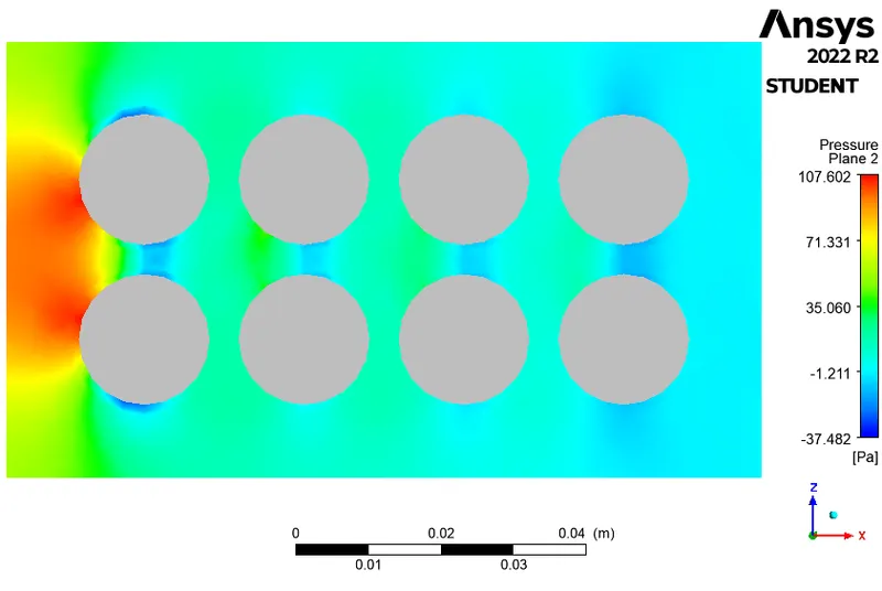
Vertical Velocity Plane
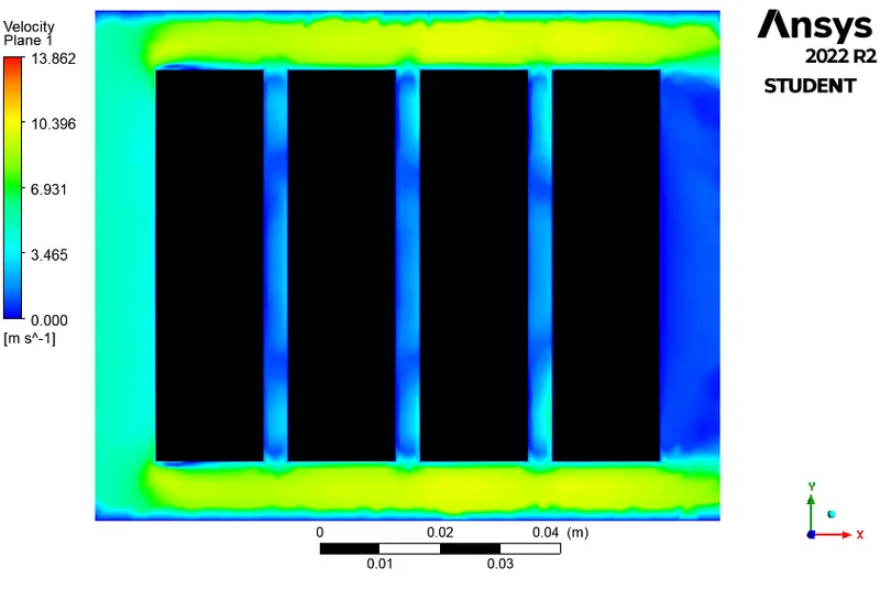
Vertical Temperature Plane
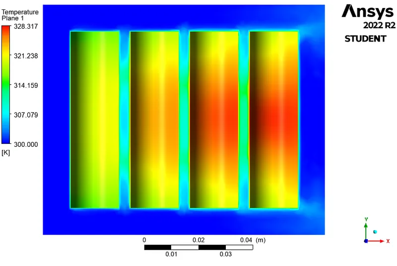
Horizental Temperature Plane
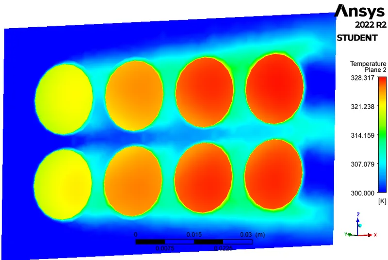
Velocity Vector in Vertical Plane
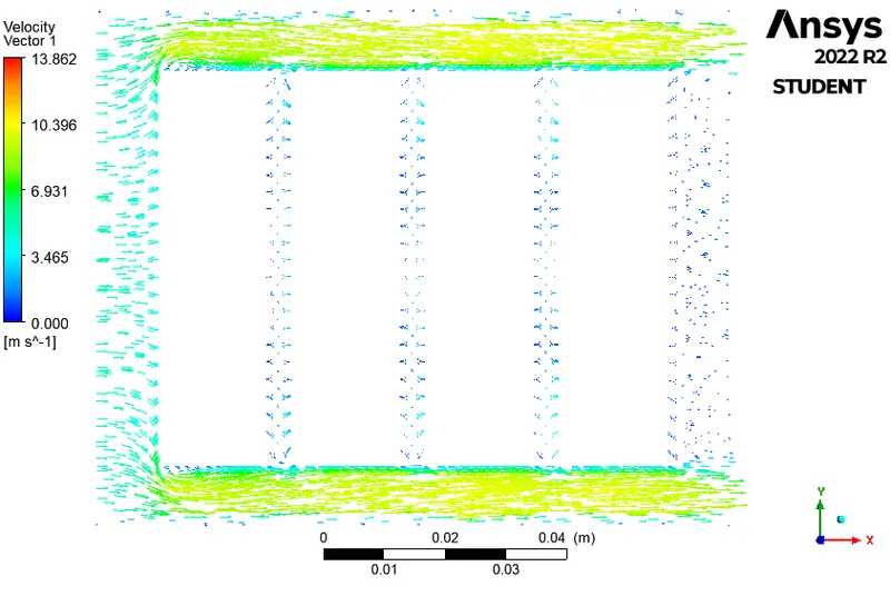
Velocity Vector in Horizental Plane
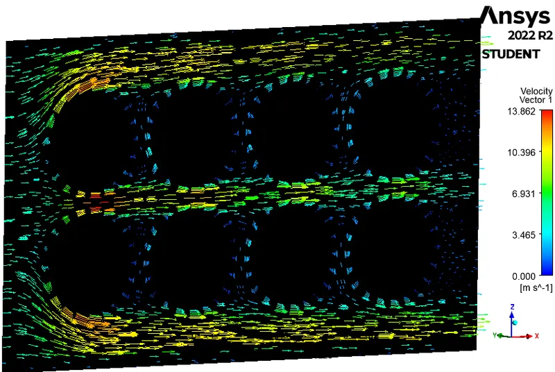
Velocity Vector in Vertical Plane with Temperature of Battery
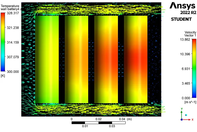
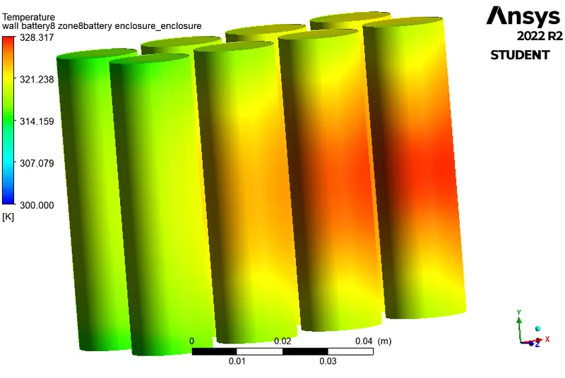
Temperature in Battery
|
Velocity (m/s) |
Max.Temp. (kelvin) |
Min. Pressure (Pa) |
Max. Pressure (Pa) |
Max. Velocity (m/s) |
| 1 | 391 | 5.11 | -1.06 | 2.82 |
| 3 | 339 | 40.65 | -11.48 | 8.36 |
| 5 | 328 | 107.60 | -37.48 | 13.86 |
Pressure Result:
The Pressure is higher at the inlet due to higher drag between air and cell as aspected.
Velocity Result:
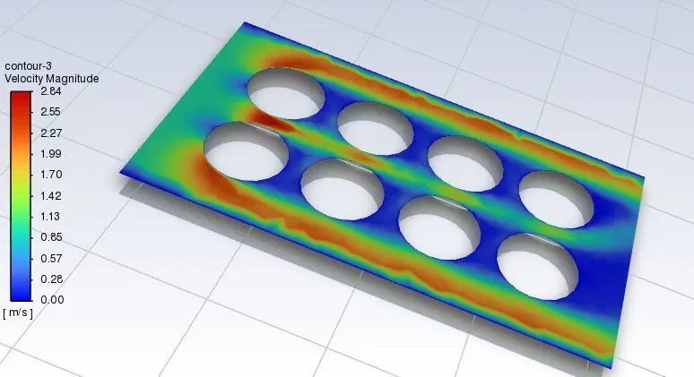
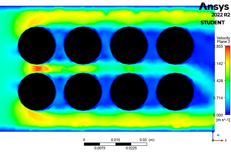
Here we can see that from velocity plot for is 1, 3, and 5 m/s at the inlet, The velocity increases at the top and the sideways of cells. This is due to the decrease in area, and as we know that as the area decreases velocity increases. The rate of heat transfer is increased also.
Temperature Result:
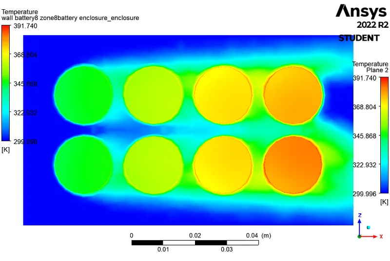
The Temperature value is shown higher in the cells due to internal heat generation. The airflow around the cells also gets heated & takes away heat from it. But here we can see that the temperature of cells decreases respectively, this is due to the increase in the velocity of air due to a decrease in the area as discussed before.
The rate of heat transfer is increased due to the higher velocity of the air. The temperature of the battery is kept maintained which is good for the operation.
The average temperature values are less when the velocity is more.
Conclusion:
Here we have seen and studied the thermal effect on the battery pack and the performance of the battery pack by changing the parameters of the simulation.
The batteries situated near the inlet are maintained at a much lower temperature than the ones near the outlet. For the same gap between batteries, we can observe that with higher velocity, the average temperature decreases.
For Lithium-ion battery 4 mm space between the batteries, and effective force convection cooling was performed with velocities of 1, 3, and 5m/s. For 5 m/s cooling is more effective compared to other velocities with a temperature of 323K.
When the Lithium-ion battery with 10W without cooling was performed we can see the temperature rising up to 392K. Hence effective cooling is required for preventing thermal runaway.
From the above plots, I have considered 5 m/s to be the best cooling now we should study by varying the space between the batteries 2, 6, and 8mm. Hence effective cooling was observed in all the cases but there are red hotspots at the last end of two batteries in 2 midsections as shown in the figure (high temperature) for all the cases.