Week 10 - Simulating Combustion of Natural Gas.
Aim :
Part I
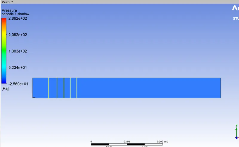
Perform a combustion simulation on the combustor model and plot the variation of the mass fraction of the different species’ in the simulation using line probes at different locations of the combustor as shown in Fig. You need to plot for CO2, H2O, CH4, N2, O2, NOx emissions & Soot formation.
Part II
As you must have observed from the above simulation, the Nox and soot is getting formed at the outlet of the combustor. Such formation has harmful effects on the environment and humans. The stringent government norms also demand the least formation of Nox and soot and to satisfy those requirements, you need to check the effect of adding the water in the fuel.
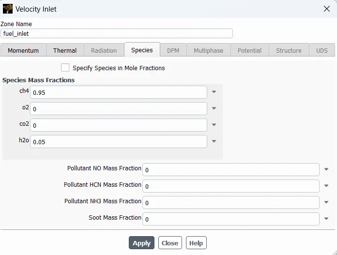
In this part, you need to add the water content in the fuel from 5% to 30% by mole and observe the effect of it on the results. It is necessary to provide line plots and contours to prove your claim.
You can use the parametric study approach if required.
Note:-
1. Use methane-air-2step as a mixture material than methane-air. [It allows to add water in the fuel or air]
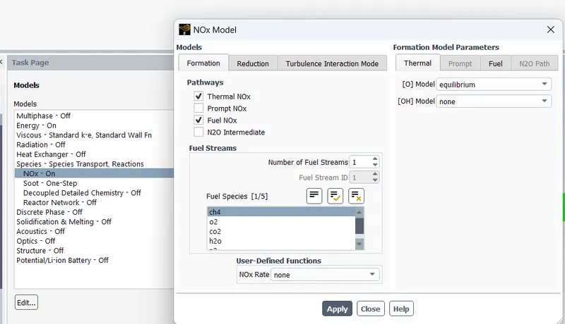
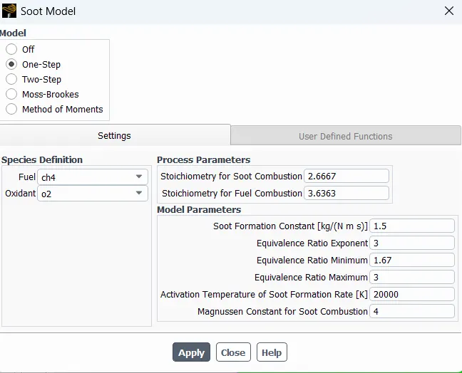
2. Use a one-step soot model to calculate the soot formation.
Combustion:
Combustion is a process in which the fuel is oxidized and large amount of chemically bound energy is released. This energy heats the products and combustion of fuel such as methane with air leads to a flame temperature of around 1900 °C (2173 K). In the combustion of methane and air, the main products are carbon dioxide and water. However, the formation of these products is very complex and hundreds of different species such as H, O, OH, CH, CH3 etc are intermediated in the combustion process. Besides carbon dioxide and water, a large number of pollutants are formed as, for instance, nitorgen oxides, carbon monoxide and soot particles. The efficiency of the combustion process depends on several parameters, such as oxygen supply, temperature history and mixing properties.
Types of Combustion Simulations:
Based on Mixing:
Non Pre-mixed combustion: This type of combustion occurs when oxidizer and fuel mixture enters the reaction zone in distinct streams or not initially mixed. Example of such a case is diesel engine where the fuel is injected just before the combustion.
Pre-mixed Combustion : The fuel and oxidizer are mixed at molecular level before the combustion similar to a case in carburetor.
Partially Pre-mixed : Its in between non pre-mixed and pre-mixed combustion where the fuel and oxidizer are partially pre-mixed at non-uniform ratios before combustion.
Based on Phase:
Fluid Phase (volumetric): The combustion occurs in a fluid phase.
Wall (Surface Reaction) : Combustion occuring on a surface wall.
Particles (Surface Reaction) : Combustion occurs on surface particles. Example coal combustion.
Porous : Combustion occuring in a porous region.
Combustion chamber simulation :
1. Geometry setup :
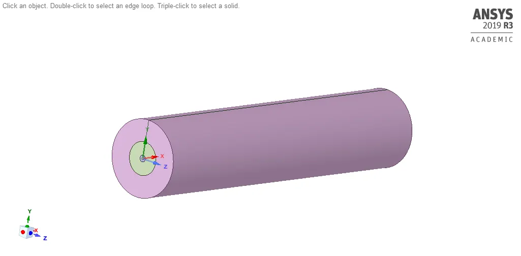
3-D geometry is converted to 2-D by using split command and sketching on the required edges and 3-D components are suppressed for physics. copy the face view to new design sheet.
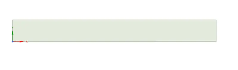
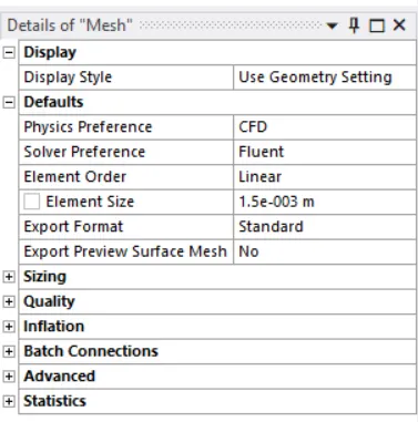
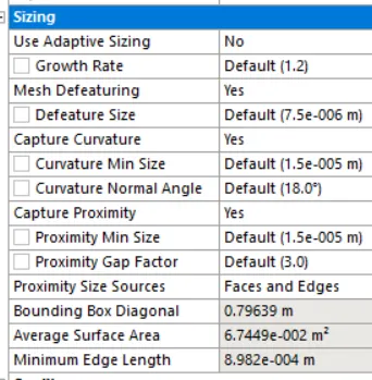
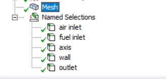
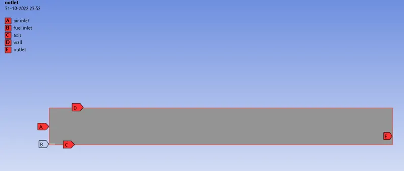
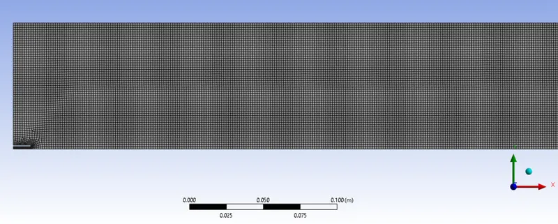
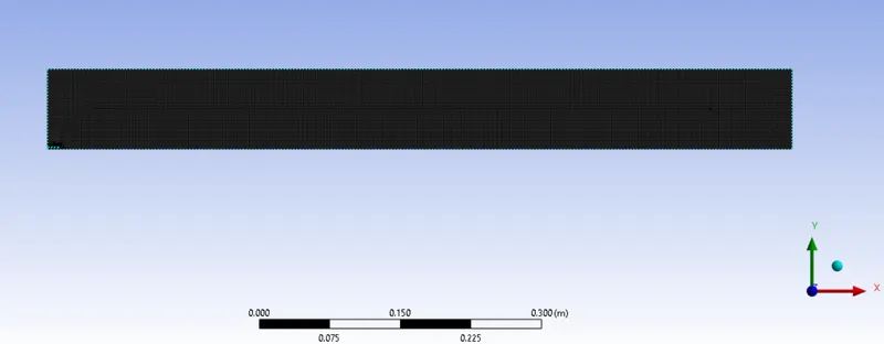
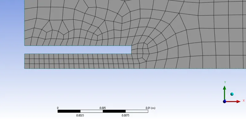
2. Meshing the Geometry :
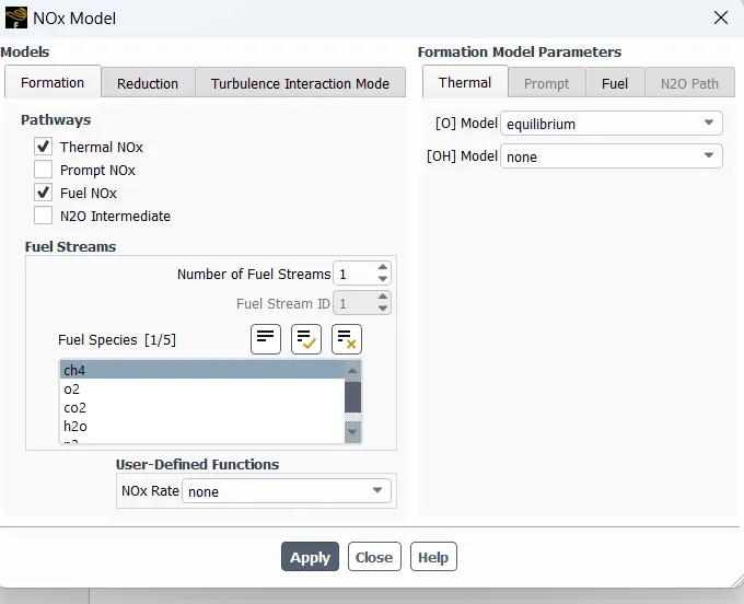
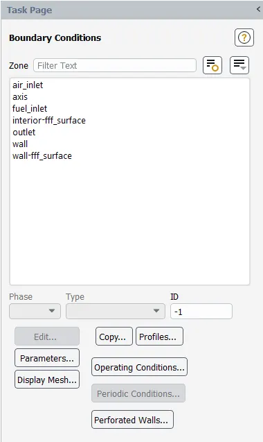
3. Setting up geometry :
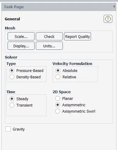
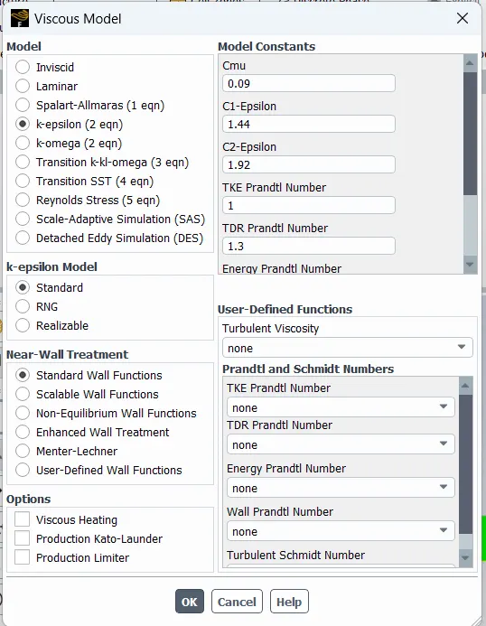
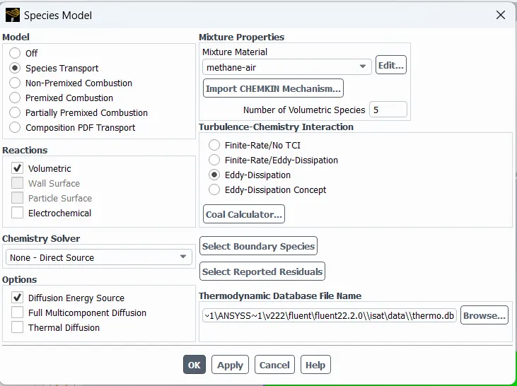
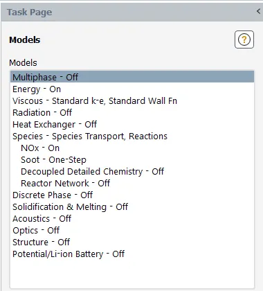
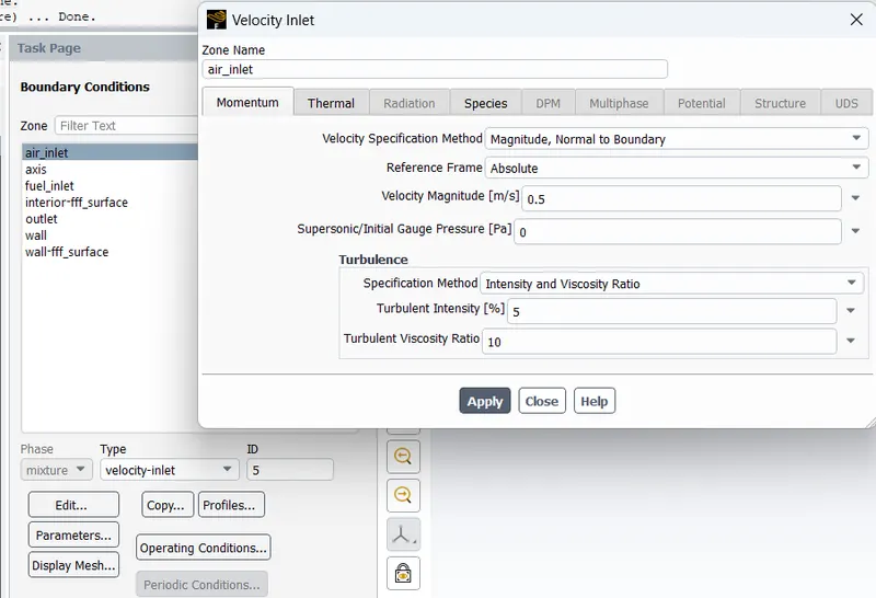
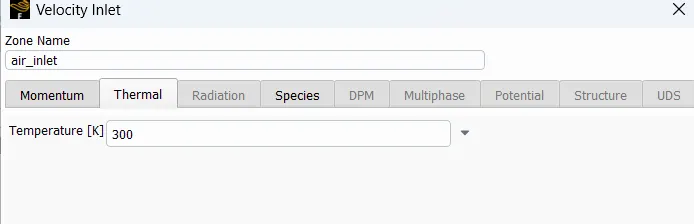
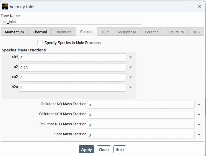
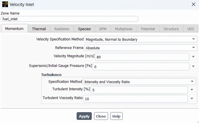
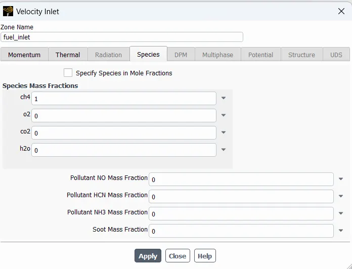
4. Solution and results :
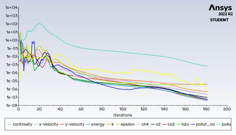
Scaled Residuals :
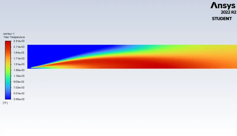
Temparature Contour: Maximum Temparature- 2310K
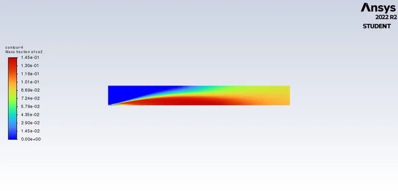
Mass Fraction Contour of CO2:
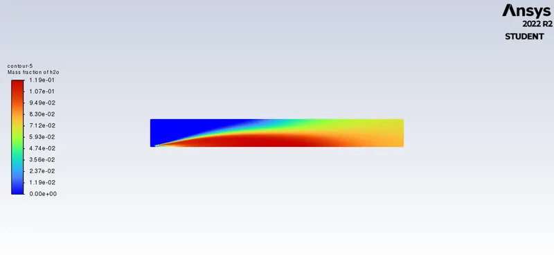
Mass Fraction Contour of H2O:
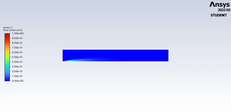
Mass Fraction Contour of CH4:
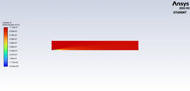
Mass Fraction Contour of N2:
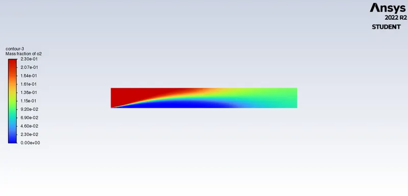
Mass Fraction Contour of O2:
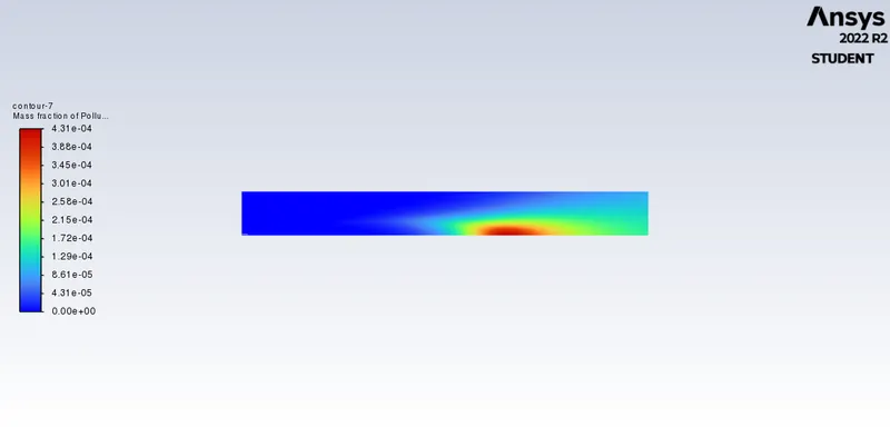
Mass Fraction Contour of NO:
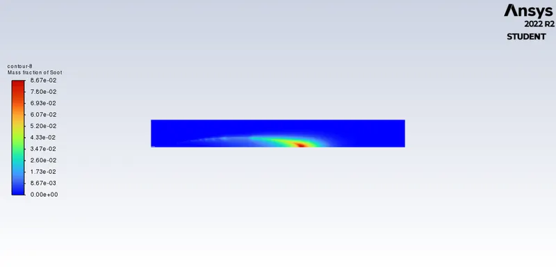
Mass Fraction Contour of Soot Formation:
Temperature contour Animation link :
Line Plots for graphs
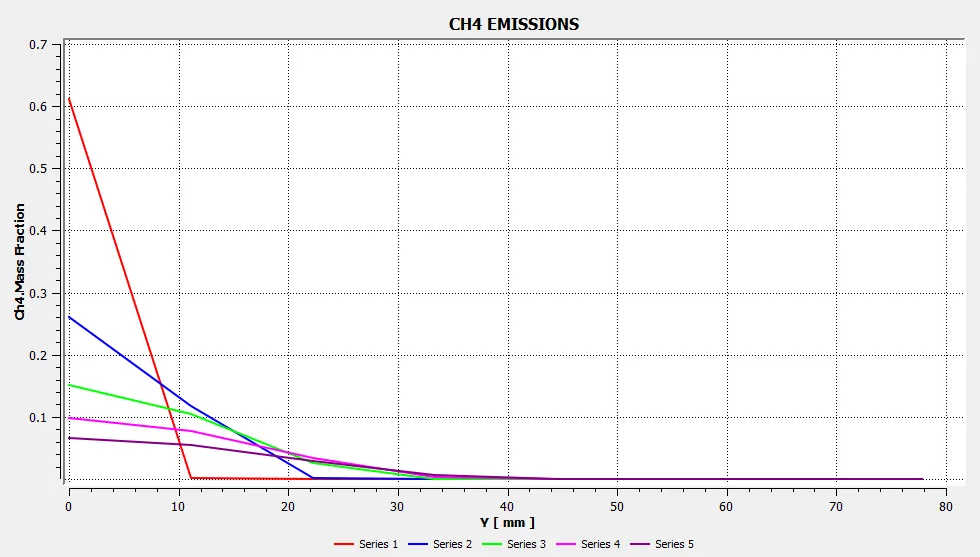
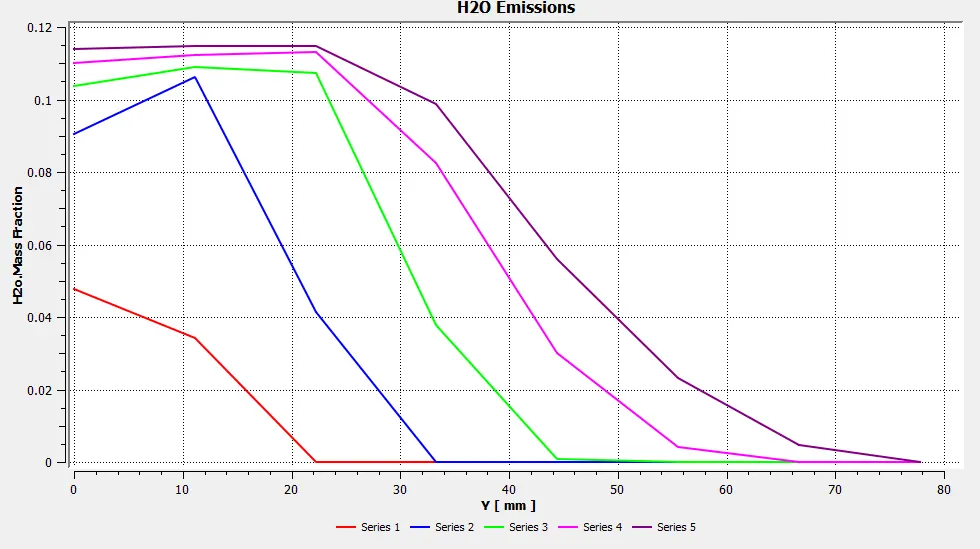
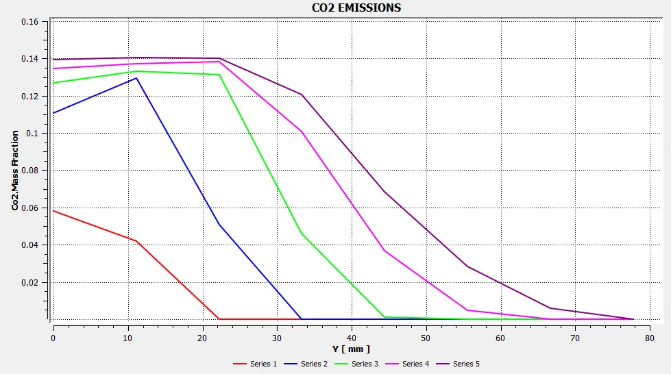
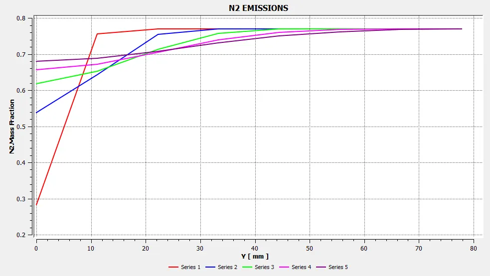
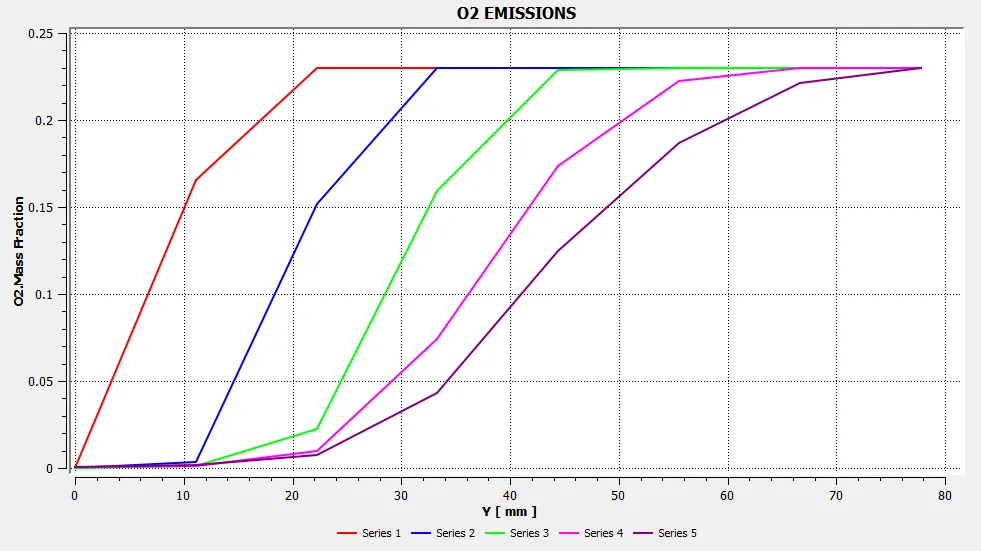
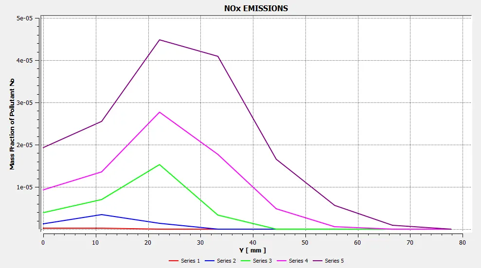
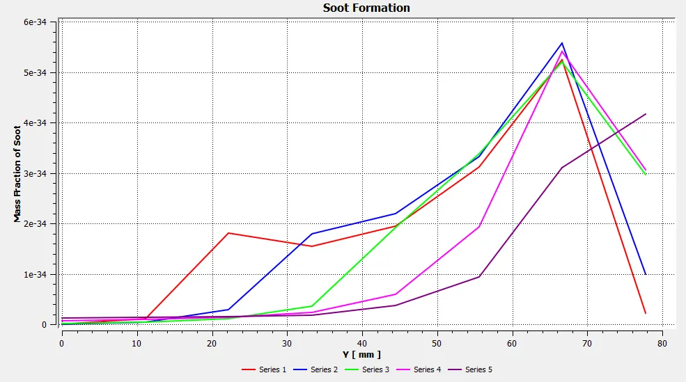
Lines are created at different locations in the direction of X-axis at 50mm, 100mm, 150mm, 200mm, 250mm for plotting graphs as shown below.
Mass Fraction Chart of CH4:
Mass Fraction Chart of H2O:
Mass Fraction chart of CO2:
Mass Fraction Chart of N2:
Mass Fraction Chart of O2:
Mass Fraction Chart of NO:
Mass Fraction Chart of Soot Formation:
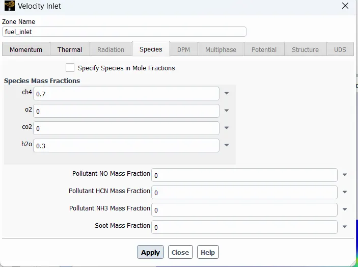
In this part, you need to add the water content in the fuel from 5% to 30% by mole and observe the effect of it on the results. It is necessary to provide line plots and contours to prove your claim.
case 1 - Oxygen 5%
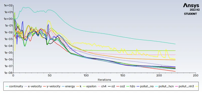
Scaled Residuals :
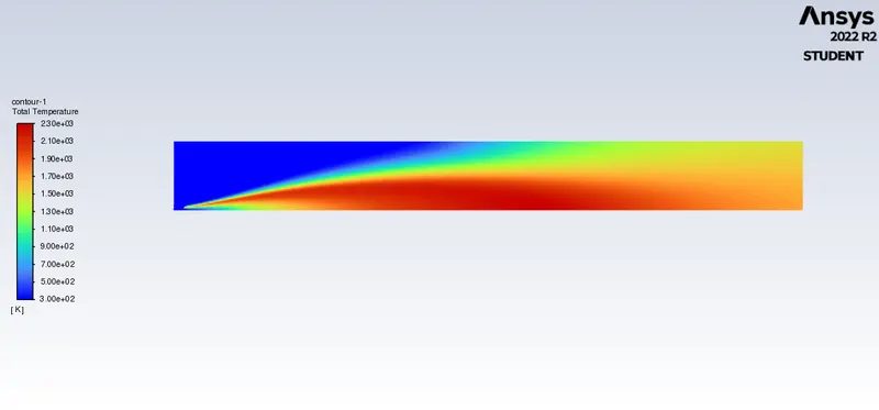
Temparature Contour: Maximum Temparature- 2300K
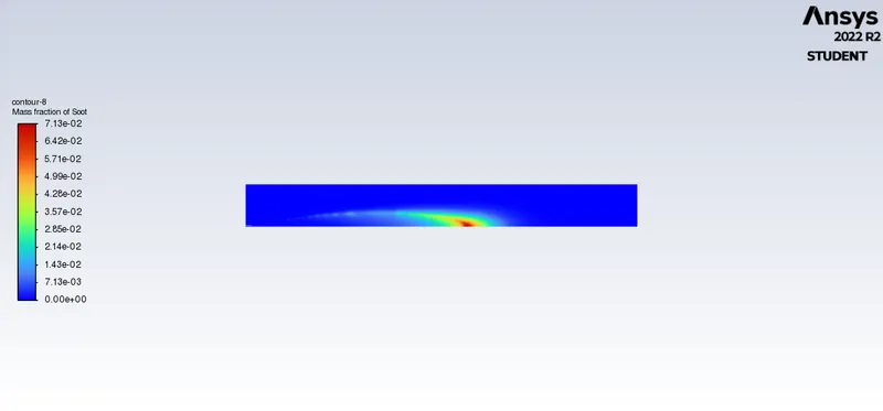
Mass Fraction Contour of Soot Formation:
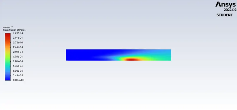
Mass Fraction Contour of NO:
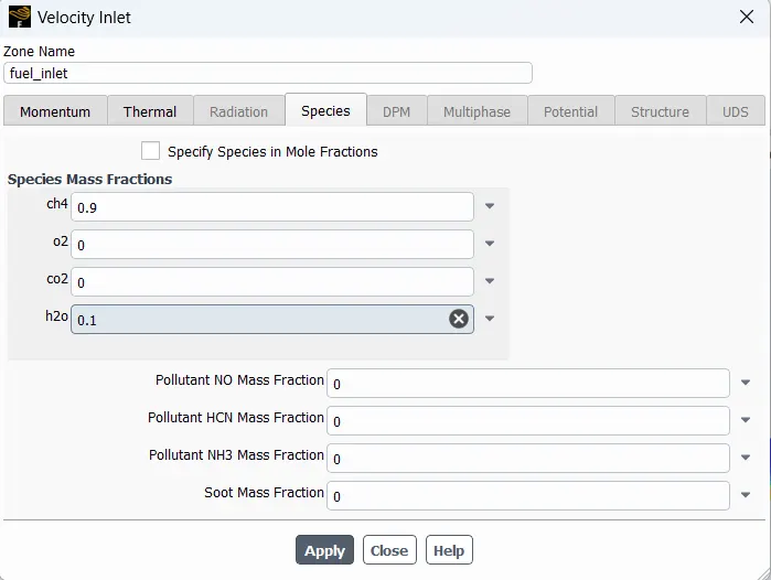
case 2 - Oxygen 10%
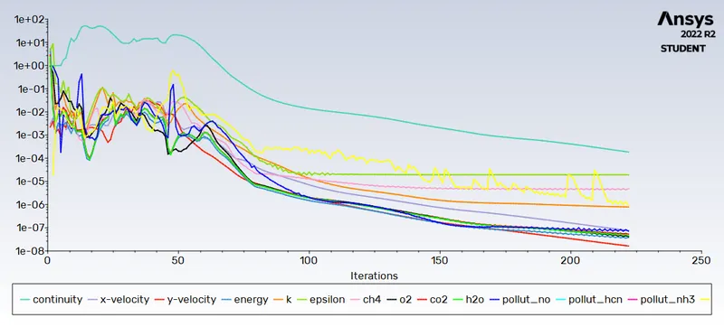
Scaled Residuals :
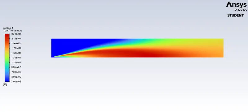
Temparature Contour: Maximum Temparature- 2300K
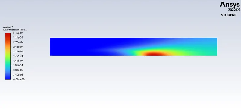
Mass Fraction Contour of NO:
Mass Fraction Contour of Soot Formation:
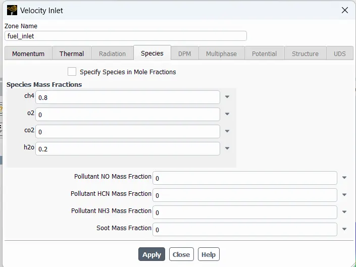
case 3 - Oxygen 20%
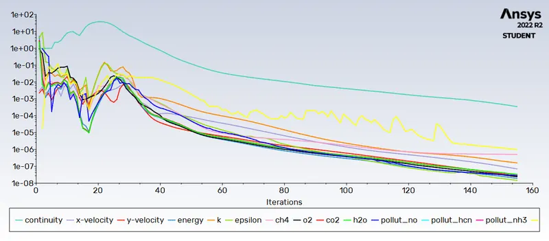
Scaled Residuals :
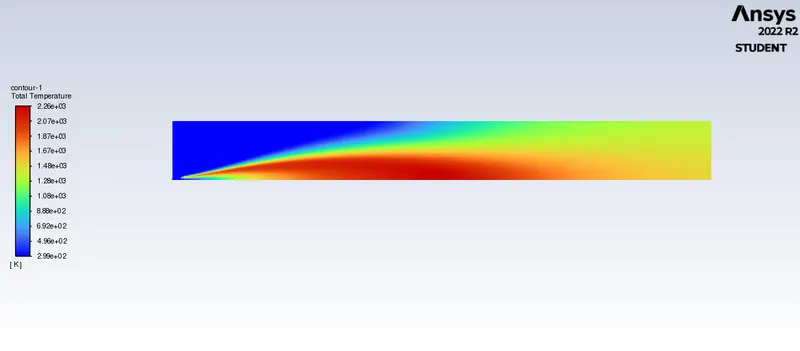
Temparature Contour: Maximum Temparature- 2260K
Mass Fraction Contour of NO:
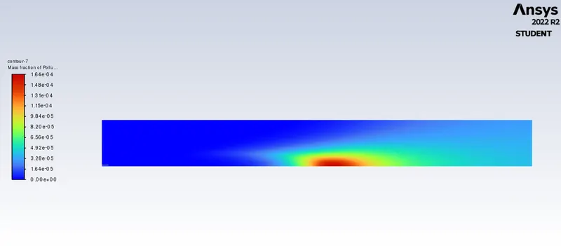
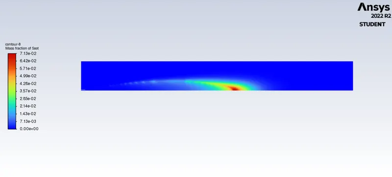
Mass Fraction Contour of Soot Formation:
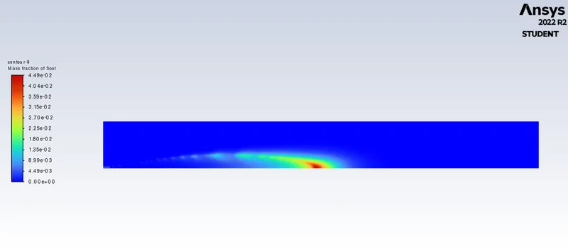
case 4 - Oxygen 30%
Scaled Residuals :
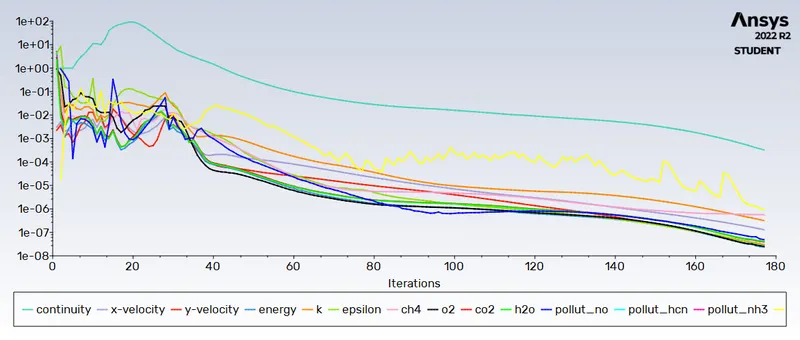
Temparature Contour: Maximum Temparature- 2260K
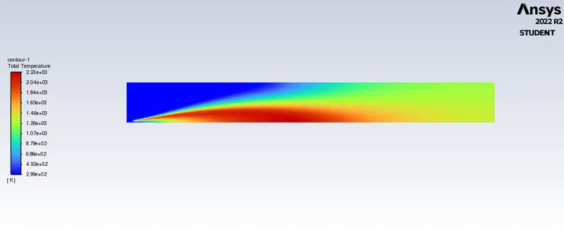
Mass Fraction Contour of Soot Formation:
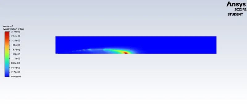
Contour of Mass Fraction Contour of NO:
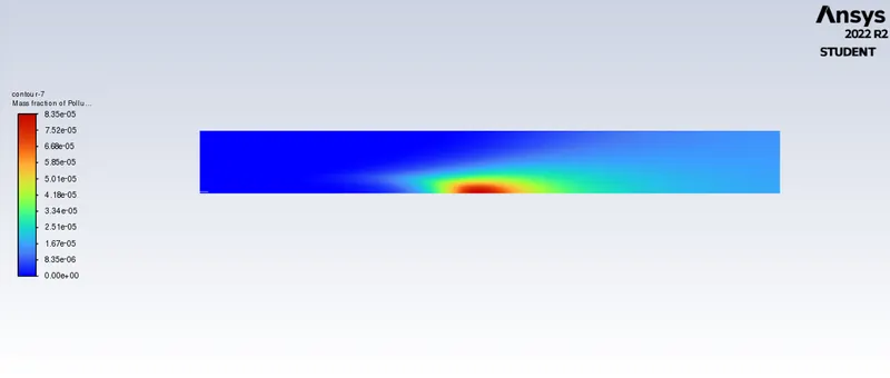
Contour of Mass fraction of ch4 :
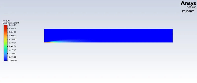
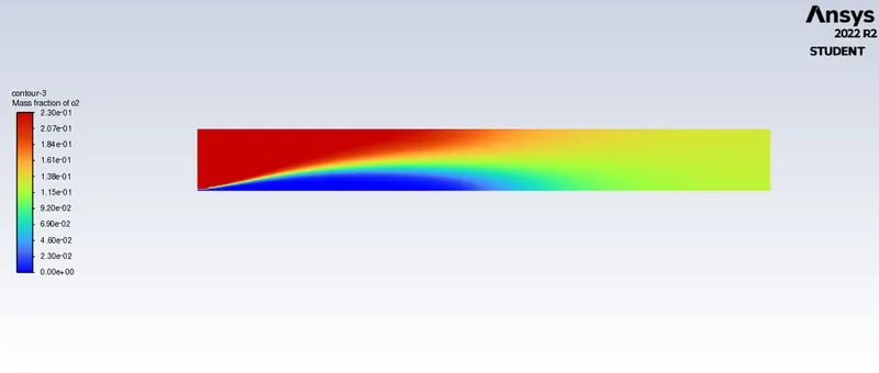
Contour of Mass fraction of o2 :
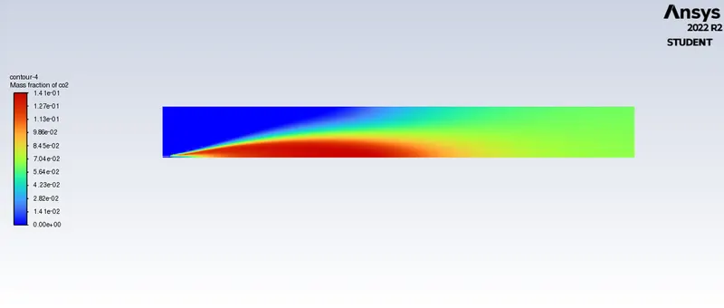
Contour of Mass fraction of co2 :
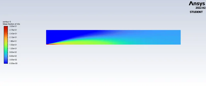
Contour of Mass fraction of h2o :
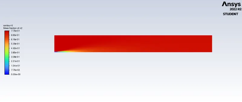
Contour of Mass fraction of n2 :
Conclusion :
In baseline mesh setup in which the whole amount of CH4 is present for as the fuel the amount of soot and NOx is greater as compared to other cases. Also the maximum temperature is about 2300 K. With the addition of water, the temperature of the gases at the outlet is decreased with the increase in % of water. The maximum Temparature observed is 2310k at H2O is 0.
Latent heat absorption of water particle during the combustion will lower the temperature resulting in the reduction of Pollutant NO. So Pollutant NO emissions decrease with an increase in the addition of water.Temperature, CO2 and H2O have similar contours, which means that species mass fraction depends on the effective Combustion. In case of soot formation, it can see that, mass fraction of soot is decreasing for case 1 and 2 but for case 3 and 4 it has increased. After checking the Mass fraction of soot contour for all the cases, it is evident that soot formation from case 1 to 4 is unbalanced but the amount of soot formation is significantly lowered for case 3 and 4. It is seen that from case 3 and 4 contour of mass fraction of soot, the formation of soot is nearer toward the outlet of burner which is common practice of soot to deposited at the outlet.
From the whole simulation it concluded that providing water with fuel will reduce the harmful exhaust emission such as NOx and Soot.