Week 10 - Simulating Combustion of Natural Gas.
l. OBJECTIVES
1. Simulate the process of combustion on a model using a mixture of fuel and air.
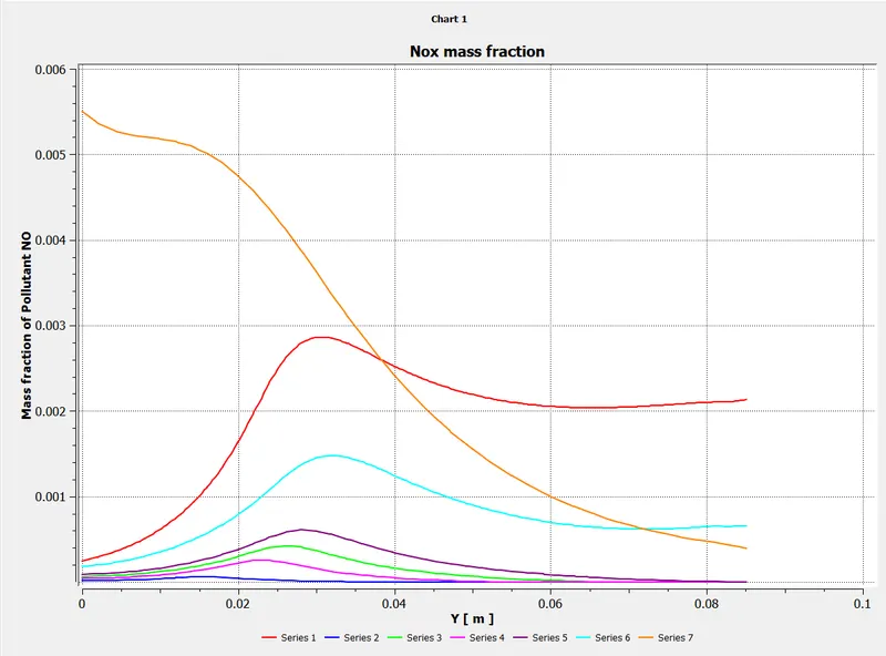
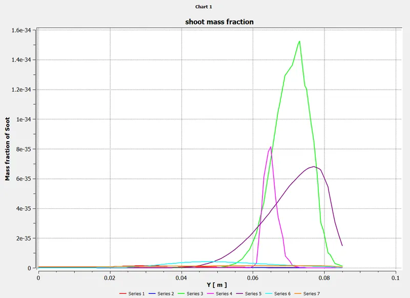
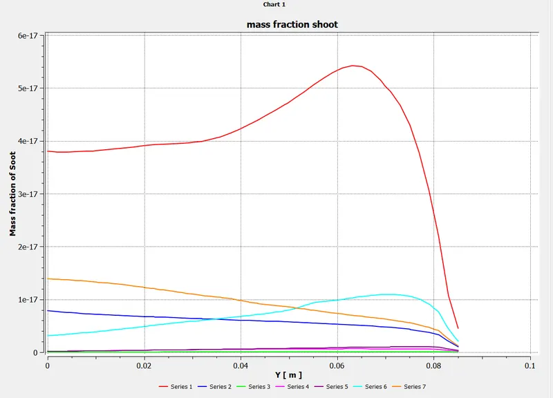
2. Plot the variation of the mass fraction of different species in the simulation using line probes at different location of the model.
ll. INTRODUCTION
1. COMBUSTION
Combustion is defined as achemical reaction in which a hydrocarbon reacts with an oxident to form products, accompanied by the release of energy in the form of heat.
Combustion manifests as awode domain during the design, analysis, and performance characteristics stage by being an integral part of various engineering applications like internal combustion engines,furnaces and power station conbustors.
2. Conbustion model for CFD Analysis
Comptational fluid dynamics modeling of combustion calls upon the proper selection and implementation of model suitable to faithfully represent the complex physical and chemical phenomenon associated with any combustion process.
The model should be competent enough to deliver information related to the species concentration, theri volumetric generation or destruction rate and changes in the parameters of the system like enthalpy, temperature and mixture density.
The model should be capable of solving the general transport equations for fluid flow and heat transfer as well as additional equations of combustion chemistry and chemical kinetics incorporated into that as per the simulating environment desired.
3. Possible types of Combustion Simulation possible in Ansys Fluent
The simulation of combustion can be divided into two types-
A. Combustion based on Mixing
- Non-Premixed Combustion
- In non-premixed combustion, fuel and oxidizer enter the reaction zone in distinct streams.
- It occours during direct injection or late injection of fuel in IC engines.
- Examples of non-premixedcombustion includes pulvarized coal furnaces, diesel internal-combustion engines and pool fires.
- Premixed Combustion
- In premixed combustion,fuel and oxidizer are mixed at the molecular level prior to ignition.
- Combustion occurs as flames front propagating into the unburnt reactants.
- Examples of premixed combustion include aspirated internal combustion engines, lean- premixed gas turbine combustors, and gas-leak explosions.
- Partially Premixed Combustion
- Partially premixed combustion systems are premixed flames with non-uniform fuel-oxidizer mixtures(equivalence ratios).
- Such falmes include premixed jets discharging into an inert atmosphere, lean premixed combustors with difussion pilot fames and cooling air jets, and imperfectly mixed inlets.
B. Combustion based on Phase
- Fluid Phase (Volumetric Reactions)
- Combustion takes place in the fluid region.
- Wall (Surface Reactions)
- Combustion takes place on the wall or a solid surface.
- Particles ( Surface Reactions)
- Combustion takes place on the Lagrangian particles.
- Combustion of coal is an example of particle combustion.
- Porous Region
- Combustion takes place in a porous region.
- The reactions in an after-treatment system is am example of combustion in the porous regions.
step1:- geometry importation
combustion model
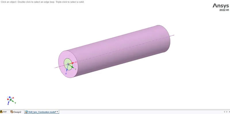
- This is 3D model, we can't run simulation for entire 3D model, it will cost a lot interms of time.
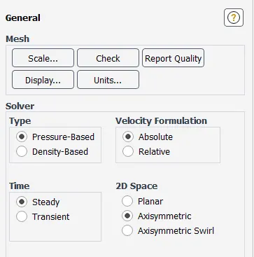
- So instead of 3D, We will perform simulation on 2D geometry, which is Axis-symmetric.
- For 2D geomerty we have to cut 3D model in two parts, and extract 2D geometry of the quadrant portion
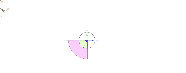
- Then we copy all faces from X-Y plane and paste it in New Design
- Then we paste it only in X-Y plane.
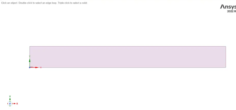
- After pasting, we merge all faces by using 'combine' command and can make it a single surface.
- So the 2D geometry can be ready for further process
step 2:- meshing the geometry
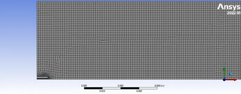
meshing details :-
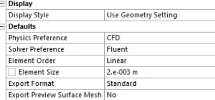

name selection :-
axis :-
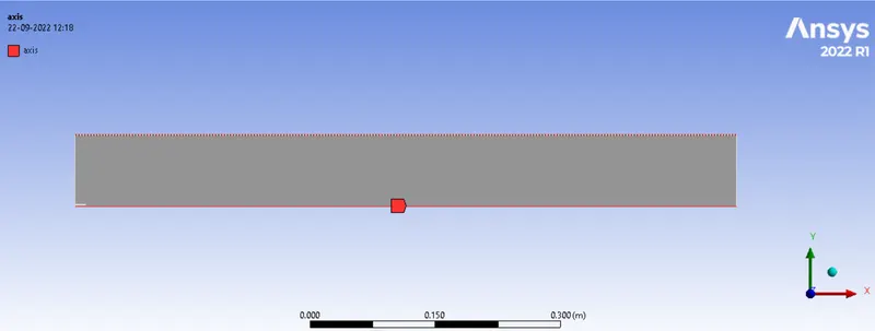
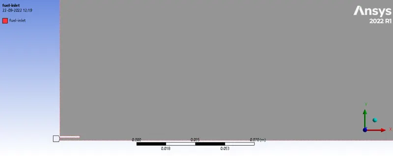
fuel inlet:-
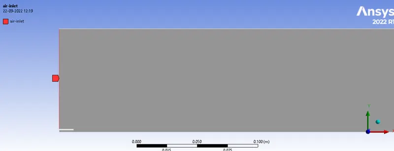
air inlet
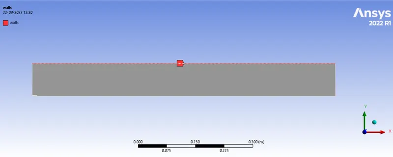
walls
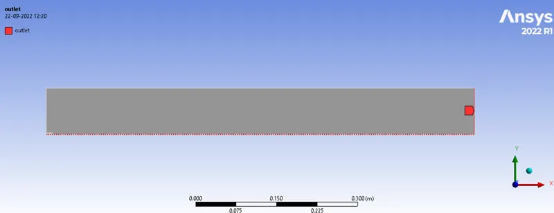
outlet
step3:-
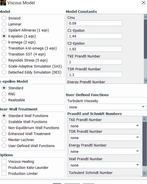
setting up the physics :-
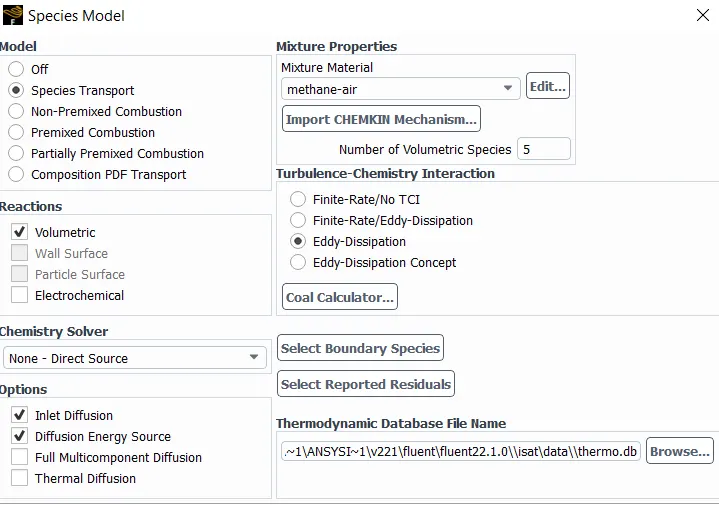
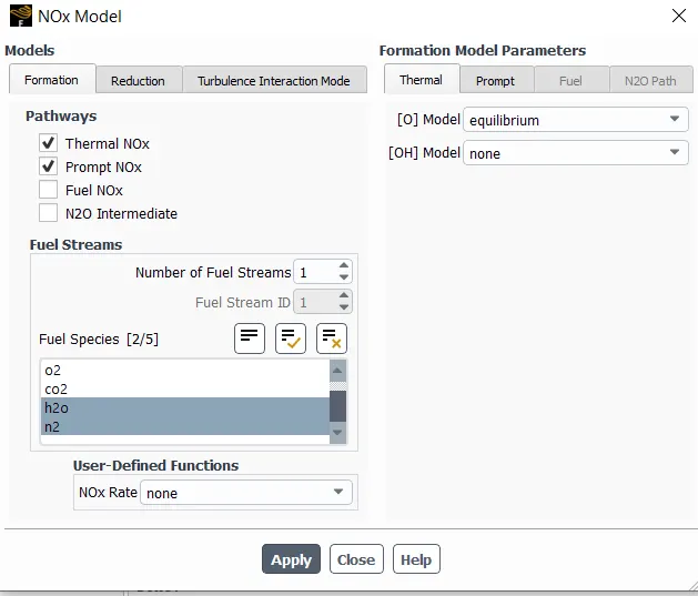
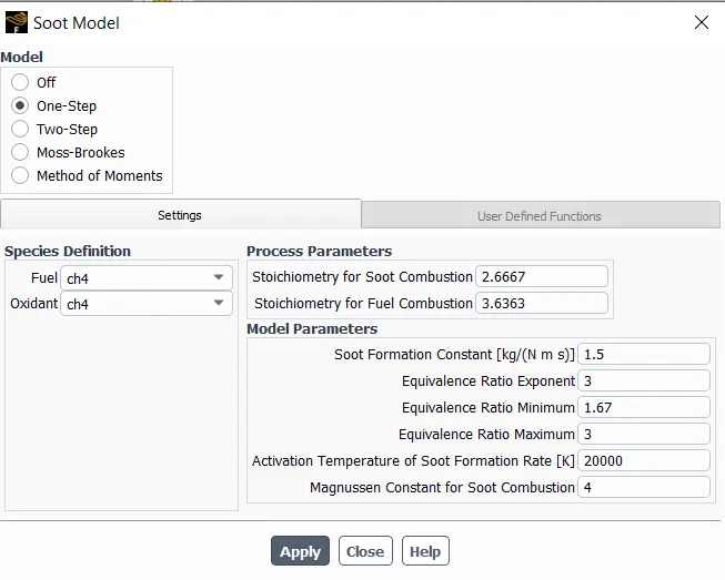
air inlet :-
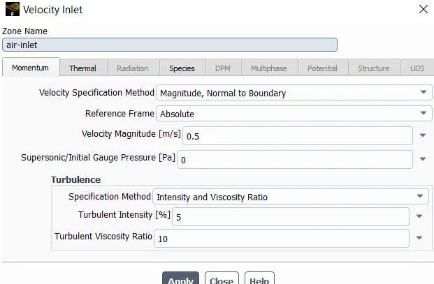
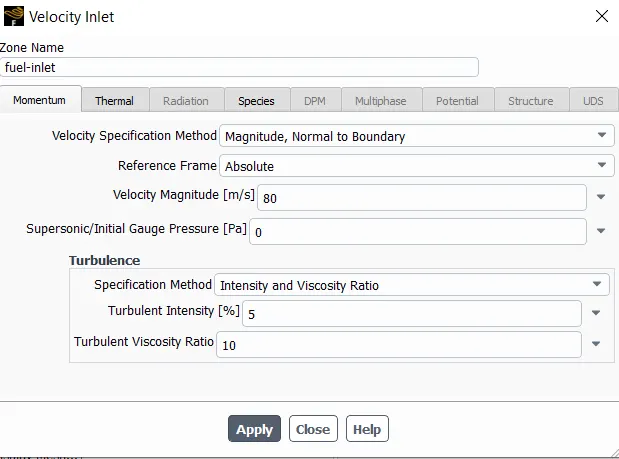
fuel inlet:-
step4:-post processing
results ;-
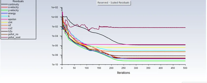
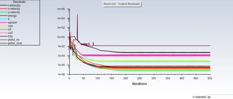
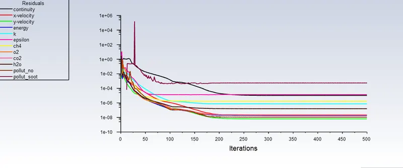
residual plot
case no-1
ch =100% and h2o=0%
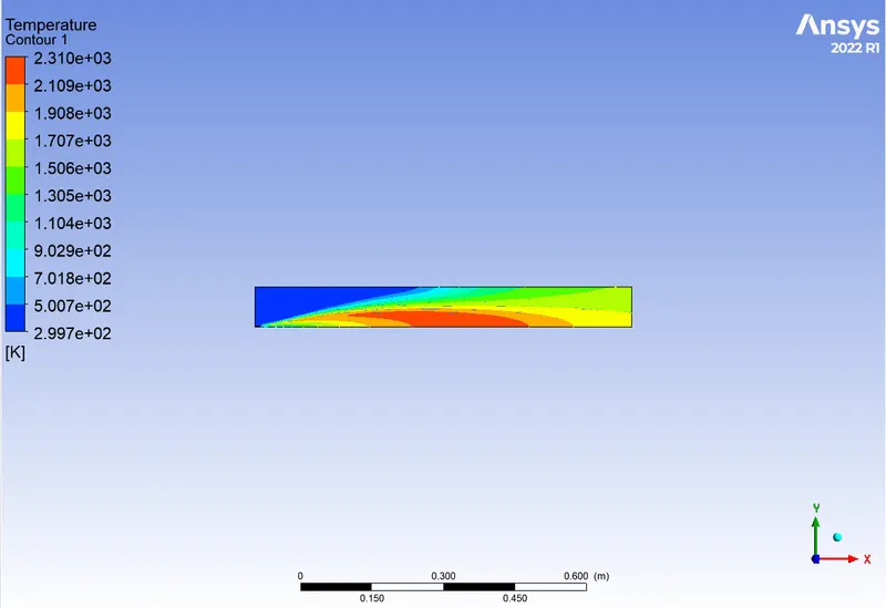
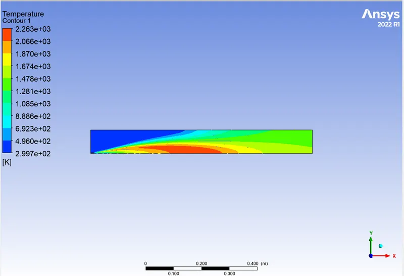
temperature countor
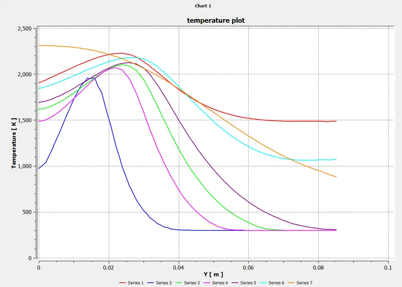
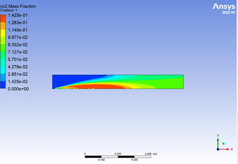
co2 mass fraction
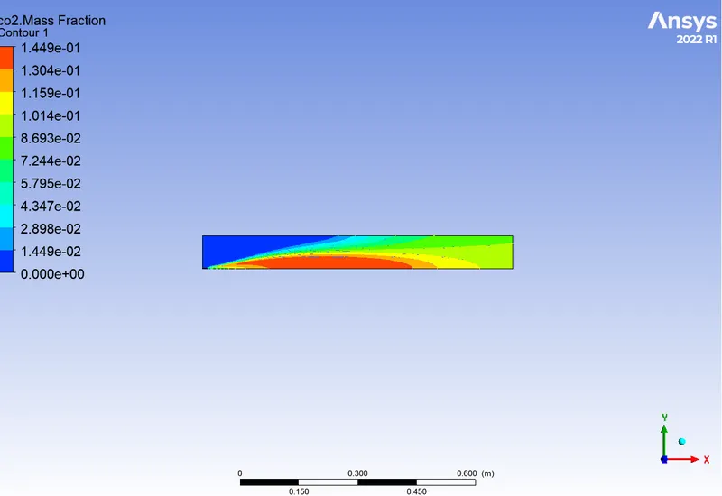
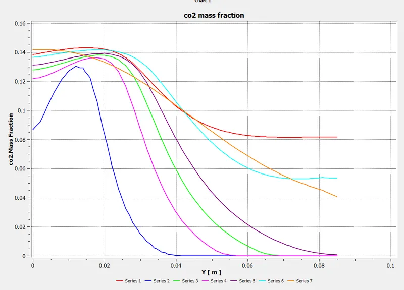
o2 mass fraction
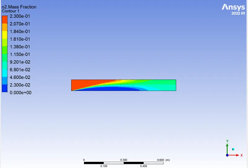
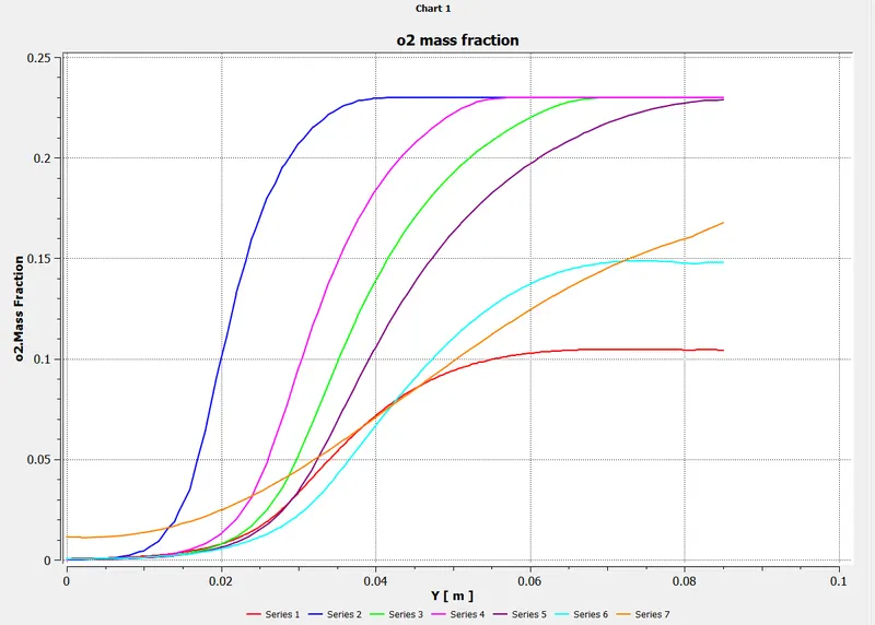
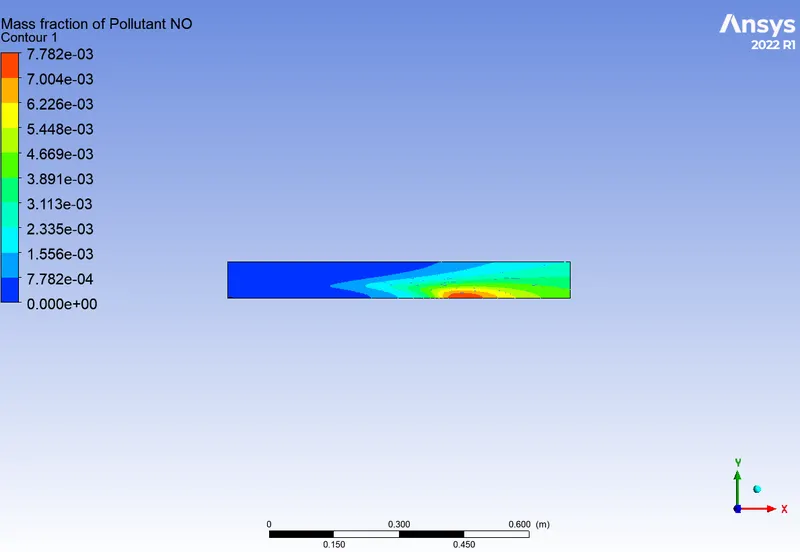
Nox mass fraction
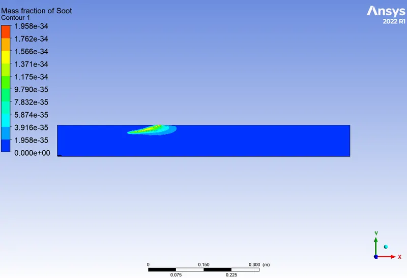
shoot mass fraction
case no2:-
ch =80% and h2o=20%
scalar residuals
temperature contour
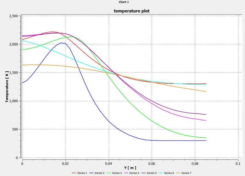
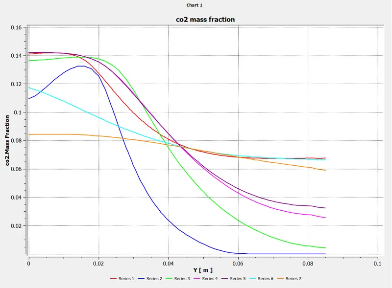
co2 mass fraction
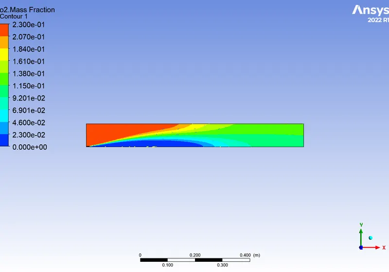
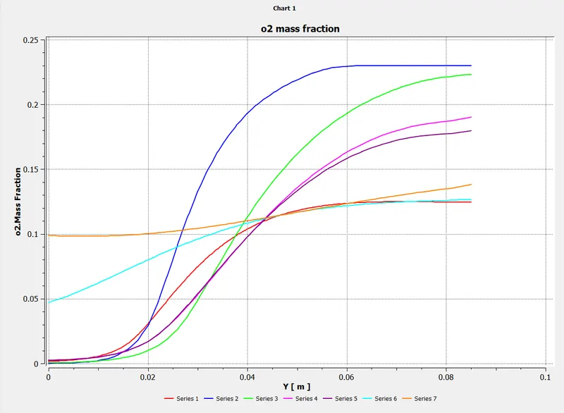
o2 mass fraction
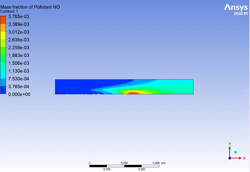
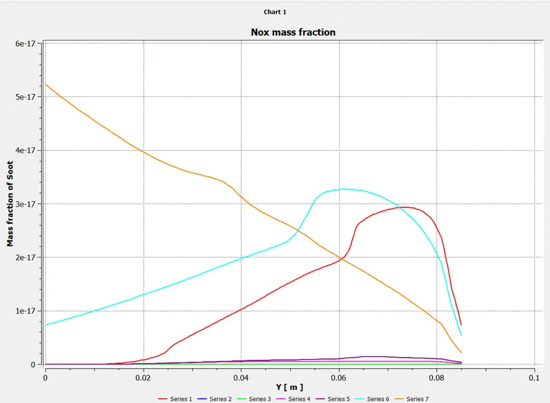
Nox mass fraction
case 3:-
ch =70% h2o=30%
scalar residuals
 \
\
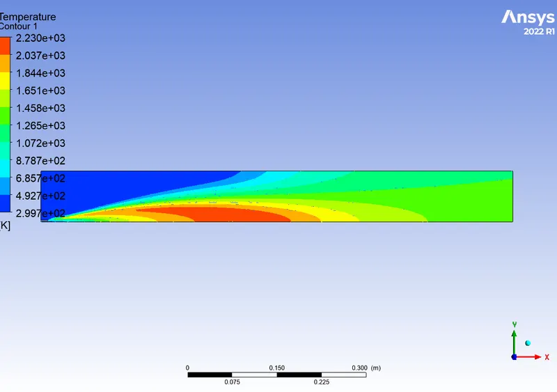
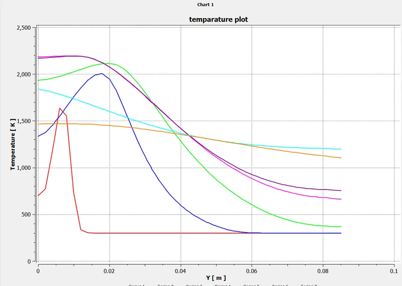
temperature contour
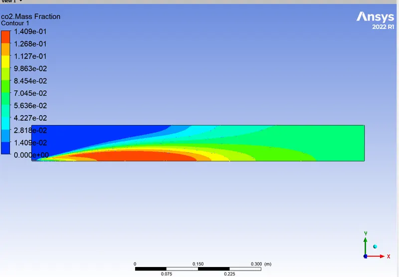
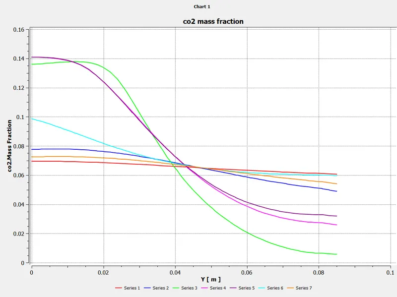
co2 mass fraction
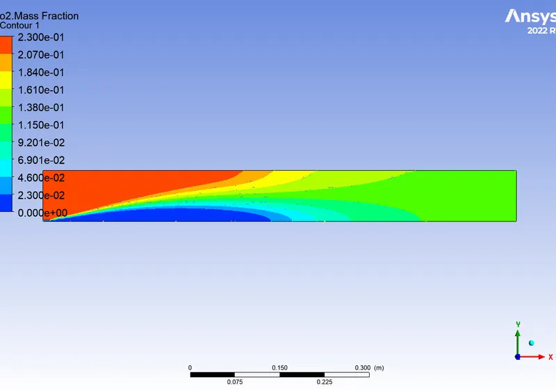
o2 mass fraction
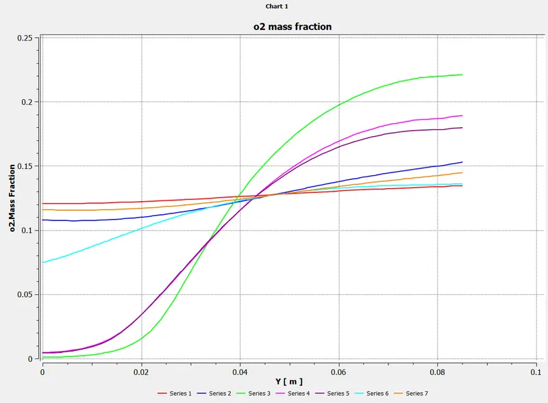
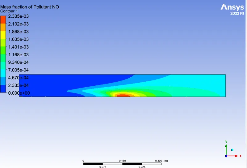
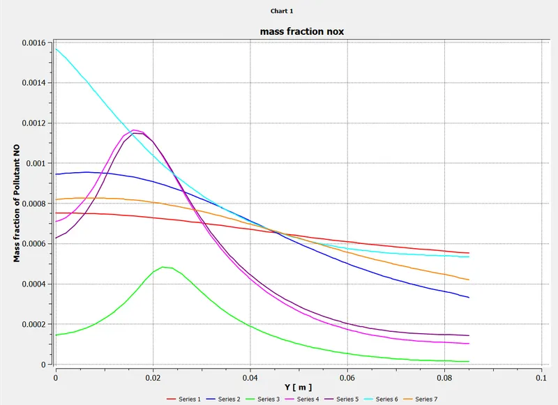
mass fraction for Nox
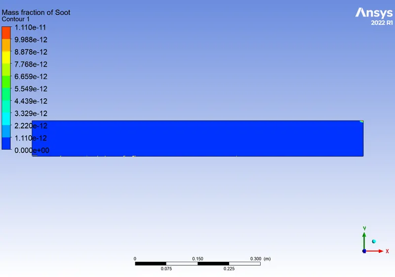
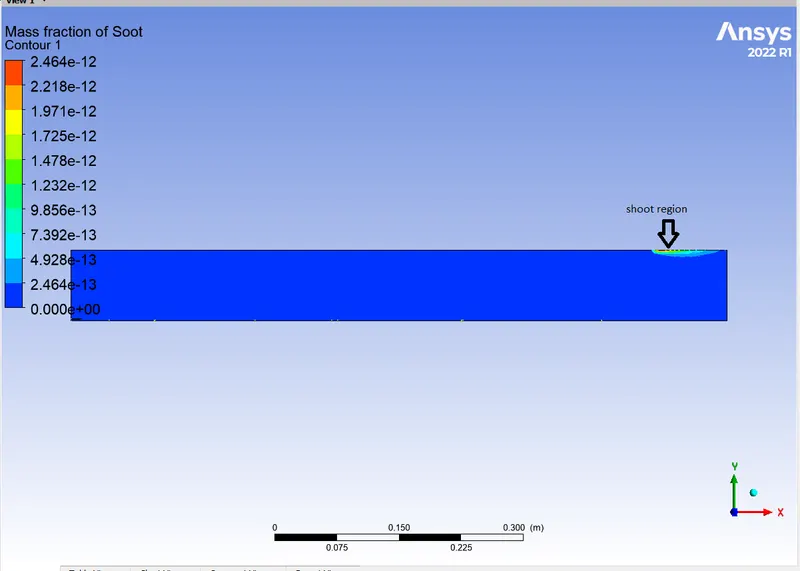
shoot mass fraction
CONCLUISION
- The simulation provides a complete temperature distribution along the geometry. Contours of various species can be studied.
- By adding water, the pollutant soot and NOx formation at the outlet is reduced. The plots of the same is also looked into.