Week 10 - Simulating Combustion of Natural Gas.
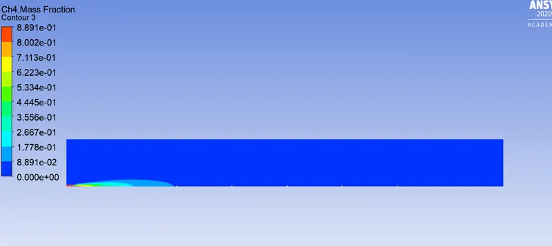
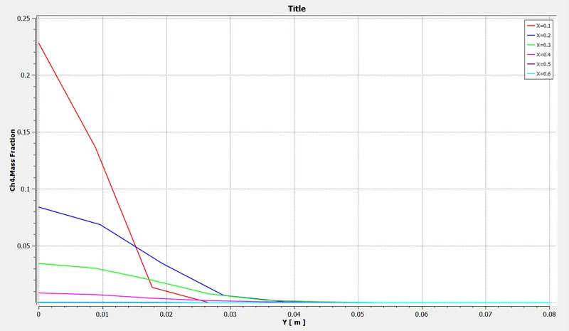
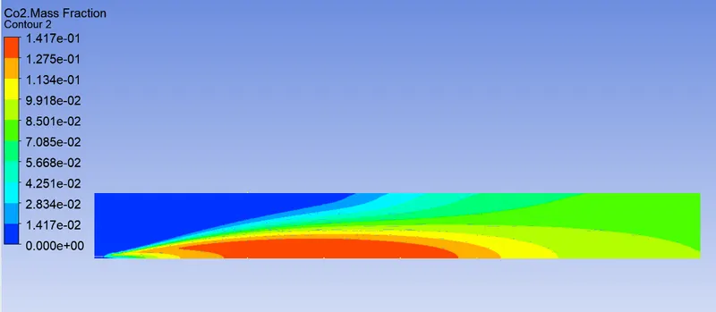
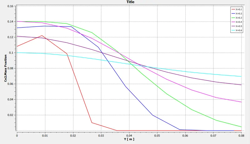
Aim:- The Aim of this project is to simulate the combustion of natural gas in a combustor. The variation of mass fraction of different species along the combustor is studied. Also the impact of introducing water content into the fuel on the mass fraction is also examined.
Theory:- Combustion is defined as the rapid oxidation generating heat. It can occur either in flame mode or non flame mode. Flame mode are further sub divided into premixed flames or non premixed flames. In the flame mode (as is in this case) there is a thin zone of intense chemical reaction propogating through the unburned fuel air mixture. The thin reaction zone is what we refer to as flame. Behind the flame are the hot product of combustion. As flame moves across the combustion space the temperature and pressure rise in the unburned gas.
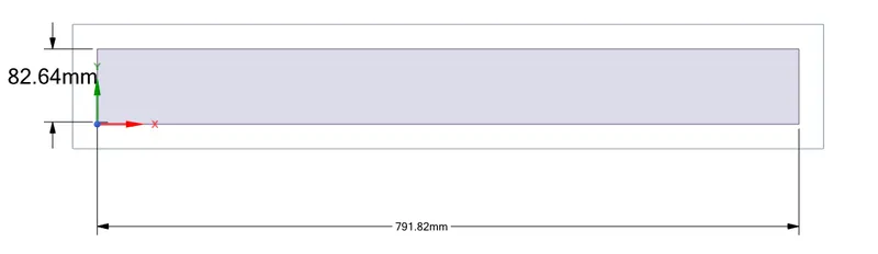
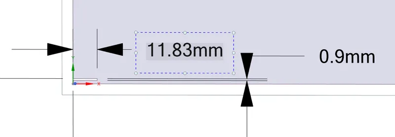
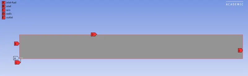
Geometry:- For this analysis we use a combustor in the shape of a concentric cylinder. Air enters the cylinder through the outer annular space at a velocity of 0.5m/s wheras the fuel mixture enters through the inner annular space of 80 m/s. Owing to computational constraints, a 2D section of the geometry is considered for the analysis as shown below.
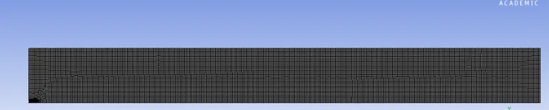
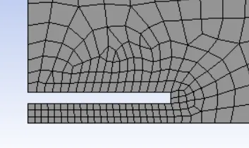
Meshing:- A mesh with size of 2mm was used with the captured proximity turned on. It resulted in a mesh with 17652 nodes and 17183 elements.
The Following Named Selections were created
Setup:-
1) General - a) Solver - Pressure Based
b) Velocity Formulation- Absolute
c) Time - Steady
d) 2D Space- Axisymmetric
2) Physics - a) Viscous Model- k-epsilon Standard with Scalable Wall Function
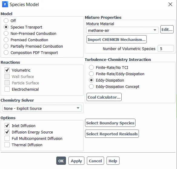
b) Species model enabled with Volumetric for Reactions,Inlet Diffusion and Diffusion Energy Selected.Eddy Dissipation selected for Turbulence Chemeistry Interaction
3) NOx and Soot emission models turned on
4) Boundaries:- i) Inlet Velocity - 0.5m/s
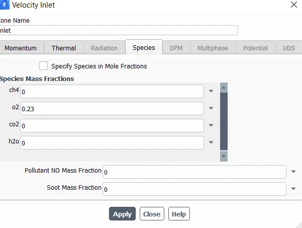
ii) Species - a) Air inlet:- Air comprises 79% Nitrogen and 21 % oxygen by volume. In terms of Mass fractions
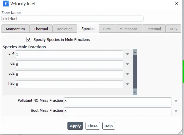
ii) Fuel inlet- Velocity 80m/s
Species
4) initialization- Hybrid and iterations run for 600.
Results
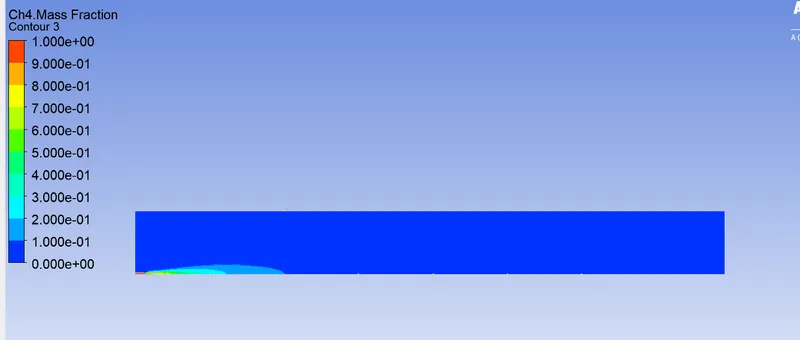
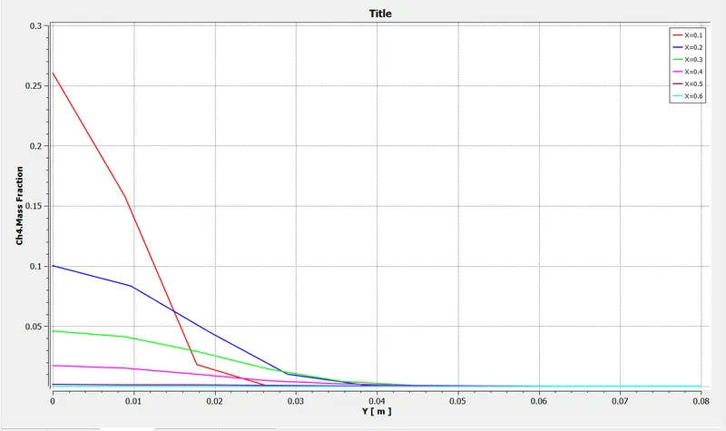
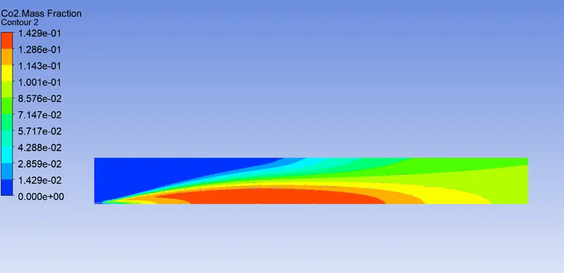
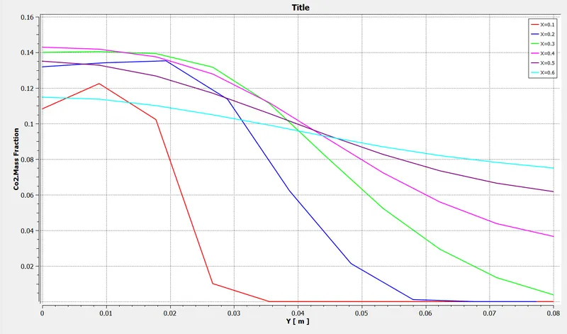
1) 0% H20 in fuel mixture
a) CH4 Mass fraction
b) CO2 Mass Fraction
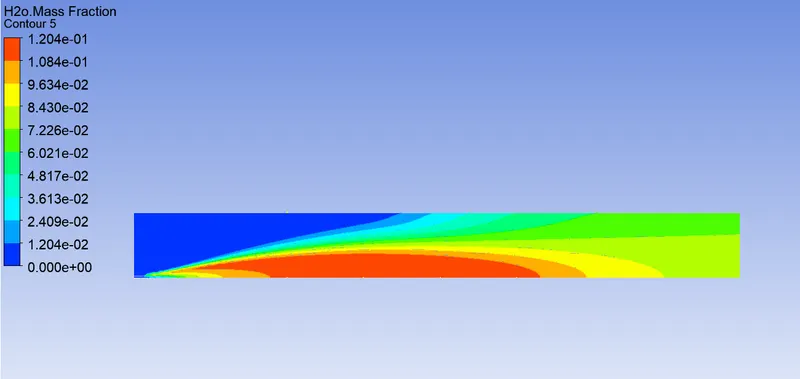
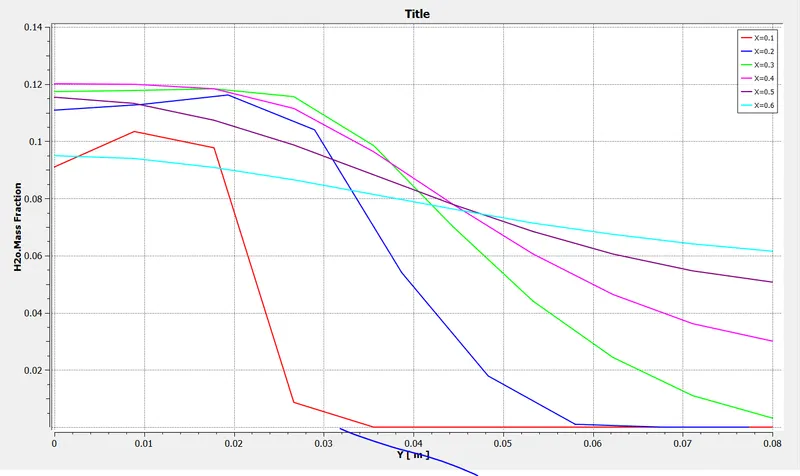
- H20
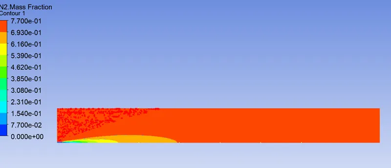
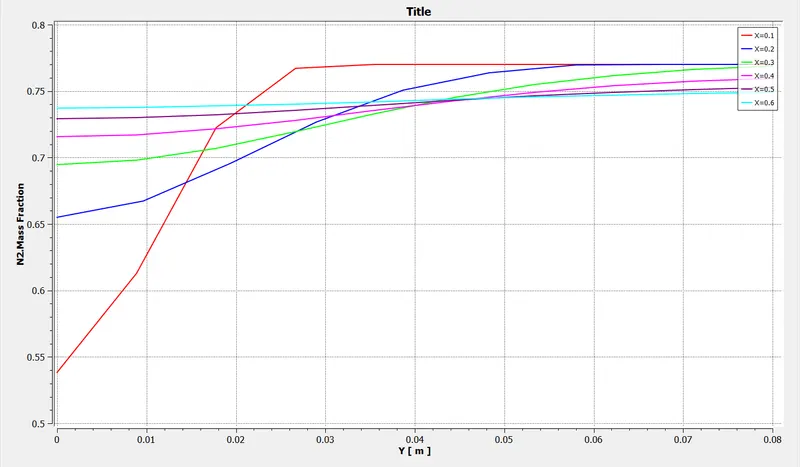
- Nitrogen (N2)
- Oxygen (O2)
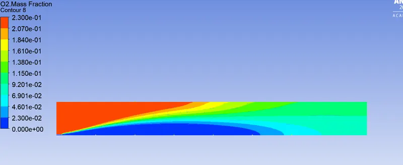
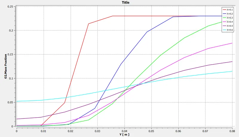
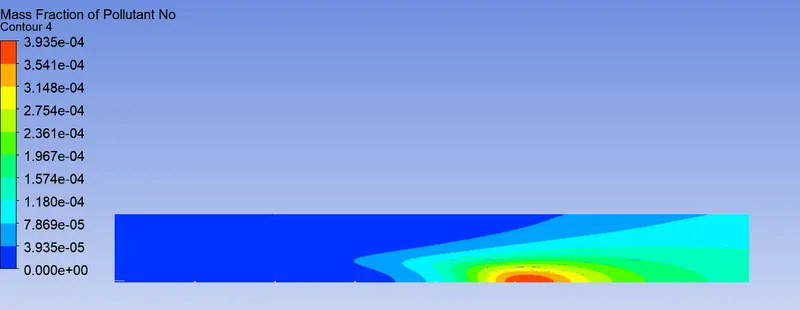
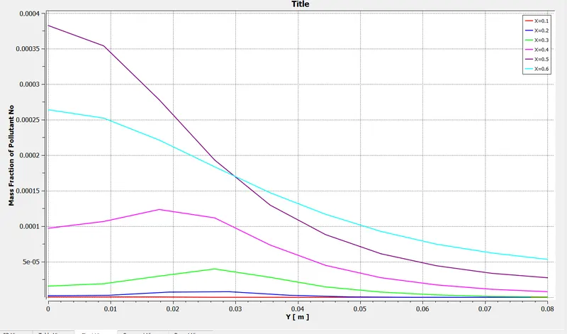
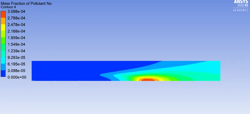
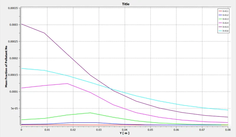
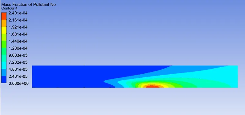
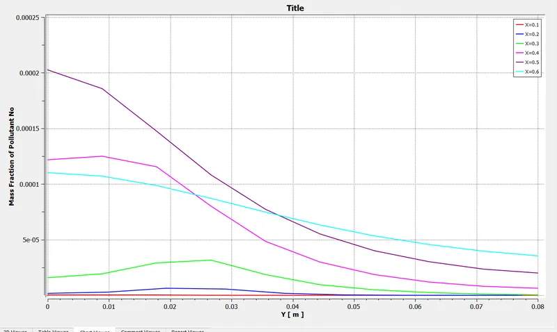
-NOx Formation
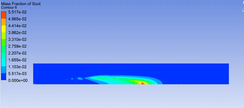
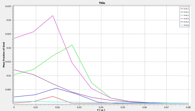
-Soot Formation
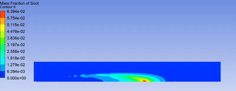
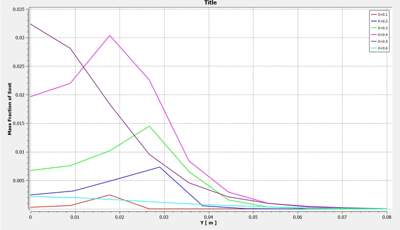
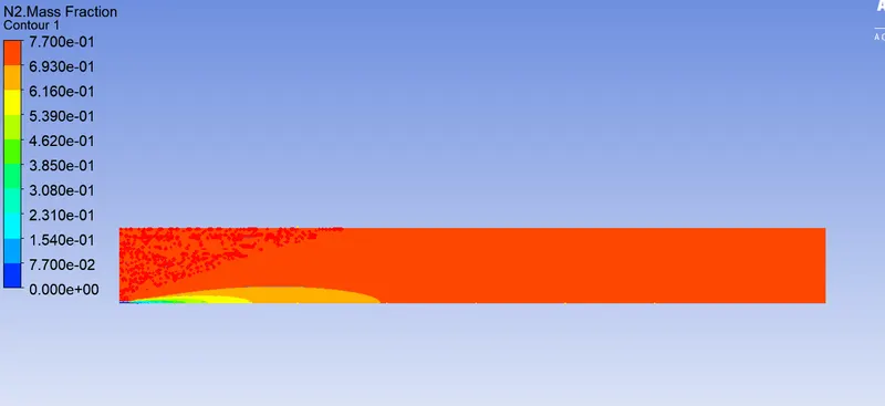
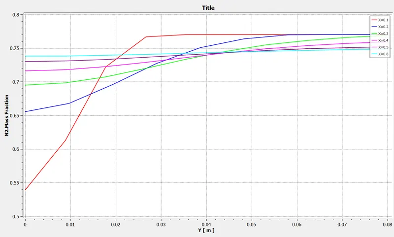
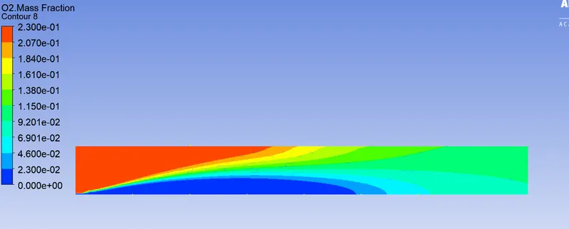
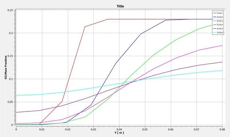
2) 5% H20 in fuel air Mixture
a) CH4 Mass fraction
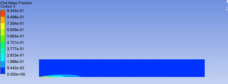
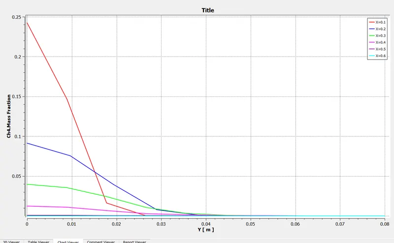
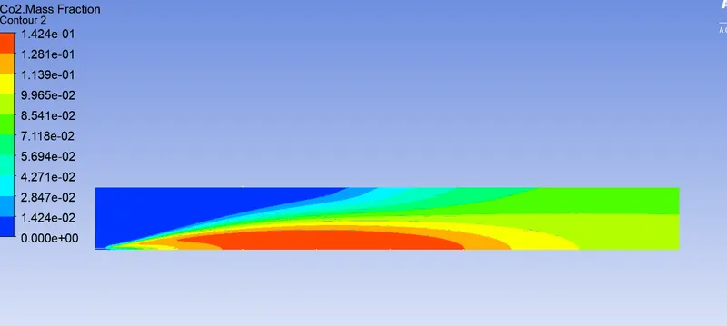
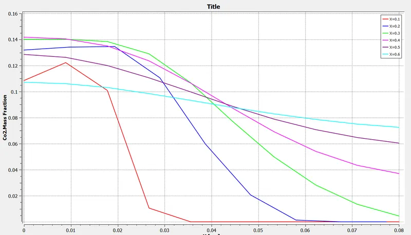
b) CO2 Mass Fraction
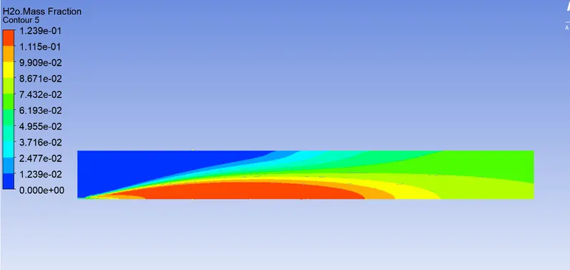
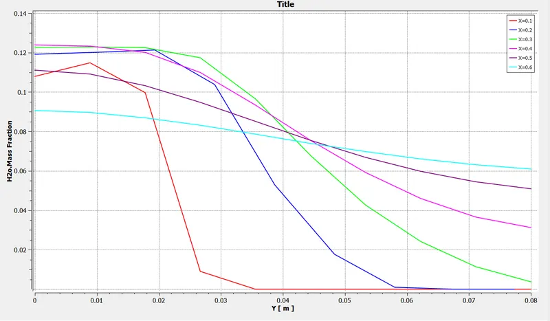
- H20
- Nitrogen (N2)
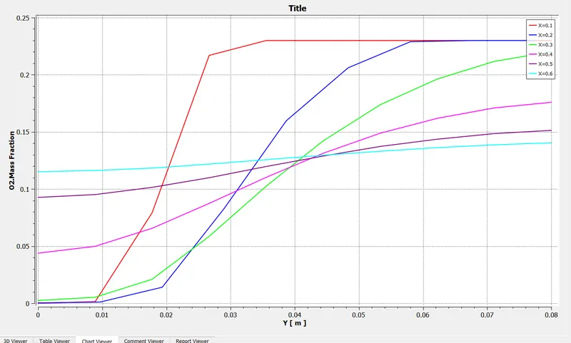
- Oxygen (O2)
-NOx Formation
-Soot Formation
10% H20 in fuel air mixture
a) CH4 Mass fraction
b) CO2 Mass Fraction
- H20
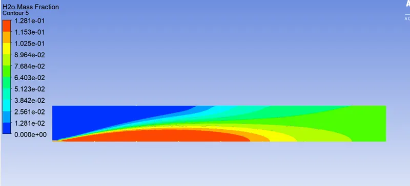
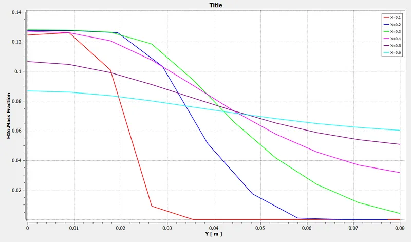
- Nitrogen (N2)
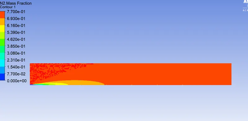
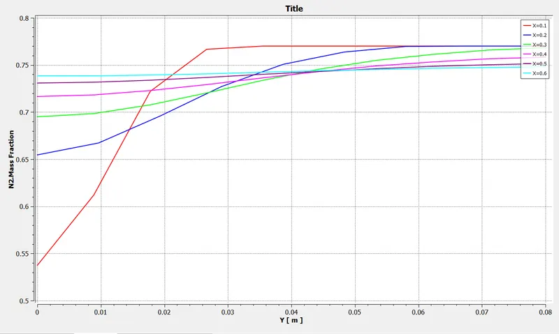
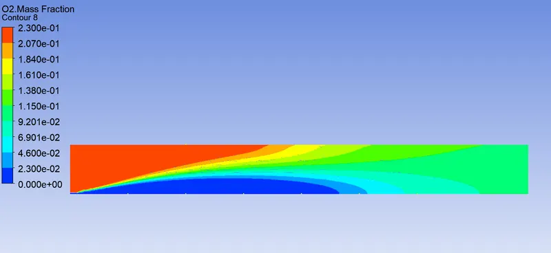
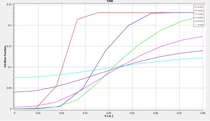
- Oxygen (O2)
-NOx Formation
-Soot Formation
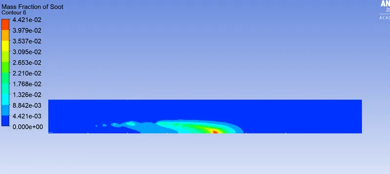
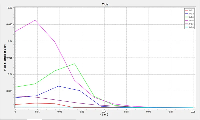
15% H20
a) CH4 Mass fraction
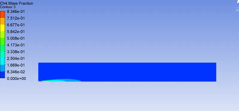
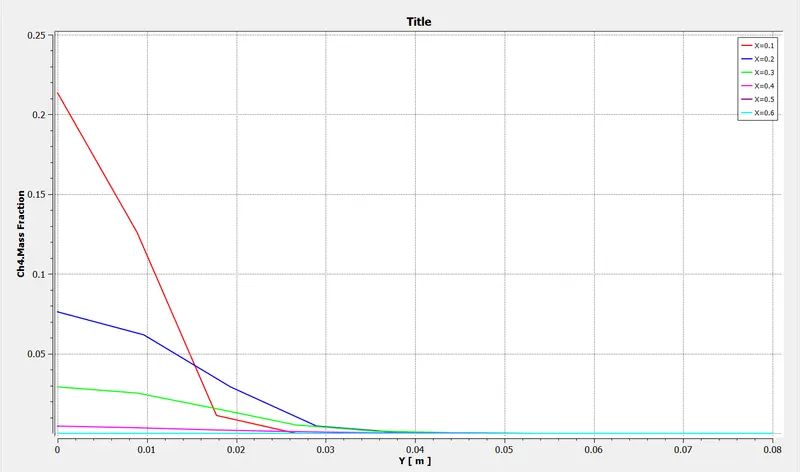
b) CO2 Mass Fraction
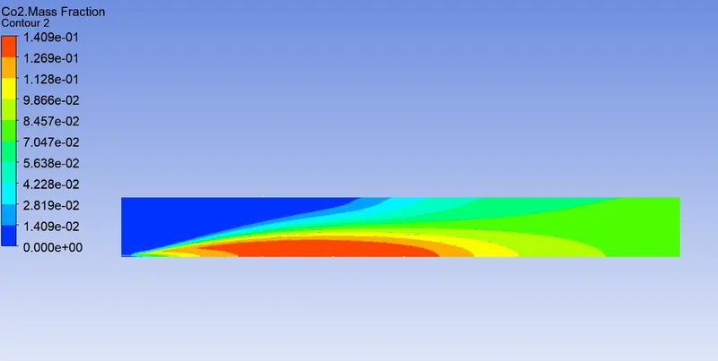
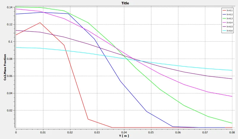
- H20
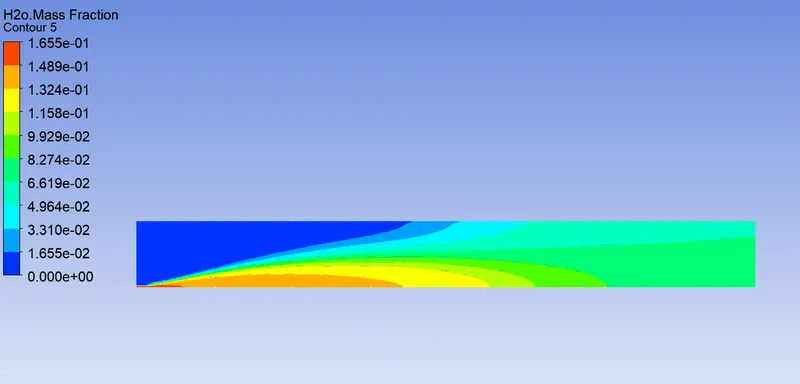
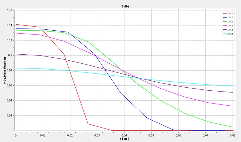
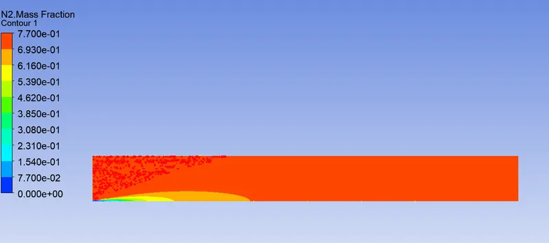
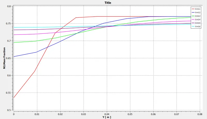
- Nitrogen (N2)
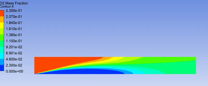
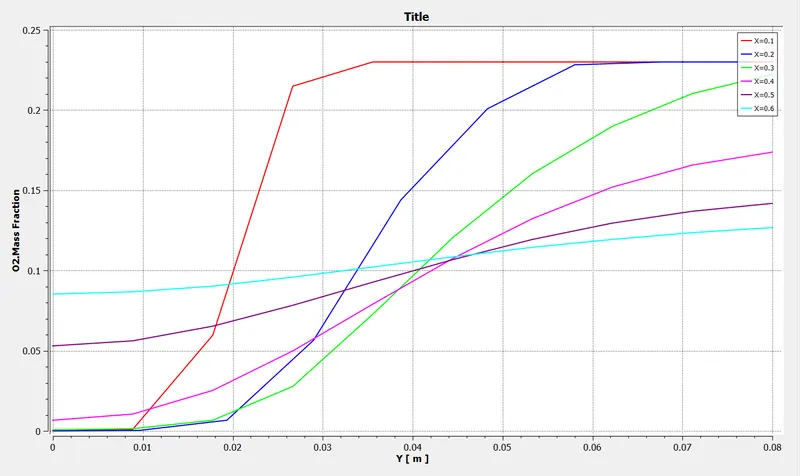
- Oxygen (O2)
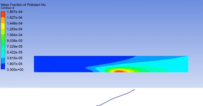
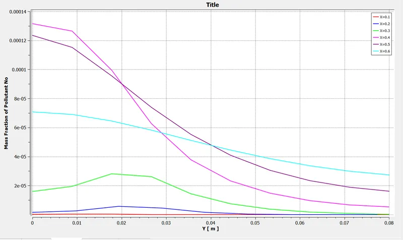
-NOx Formation
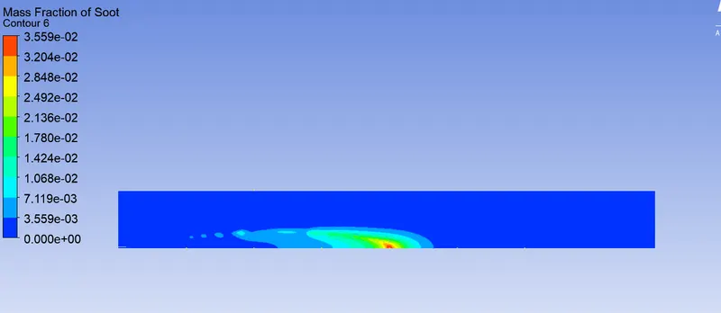
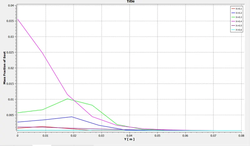
-Soot Formation
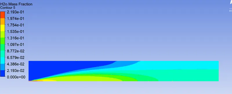
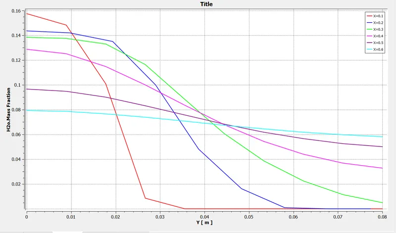
20% H20
a) CH4 Mass fraction
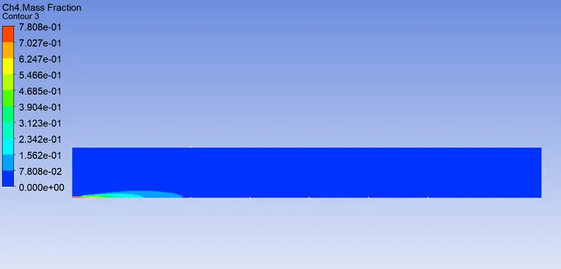
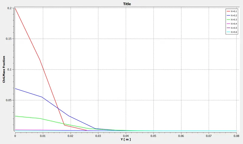
b) CO2 Mass Fraction
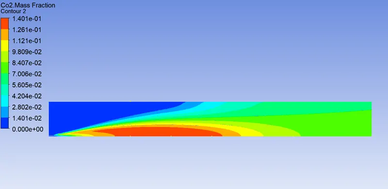
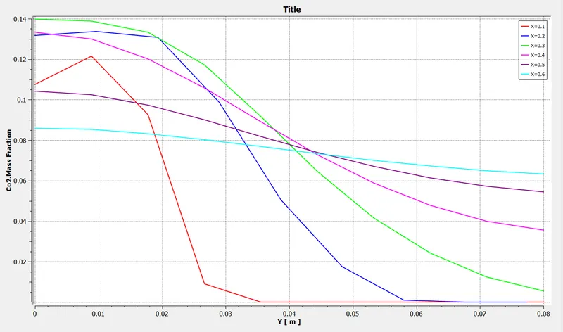
- H20
- Nitrogen (N2)
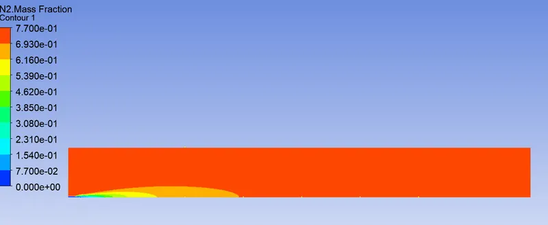
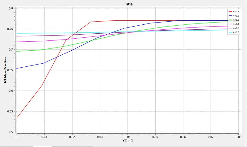
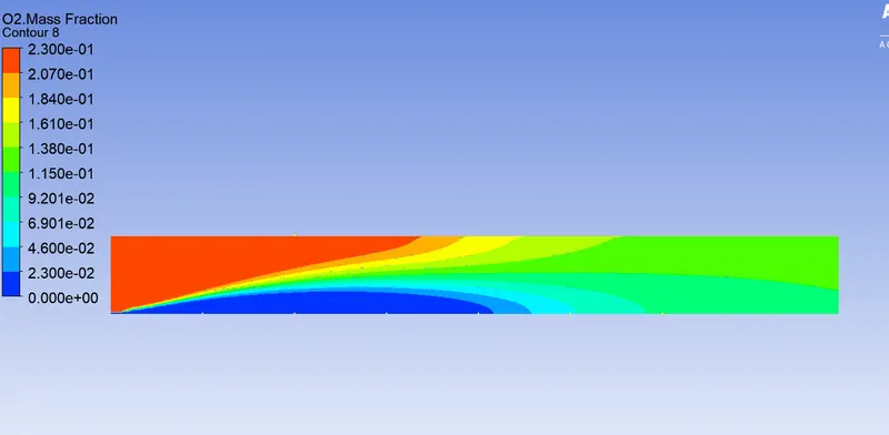
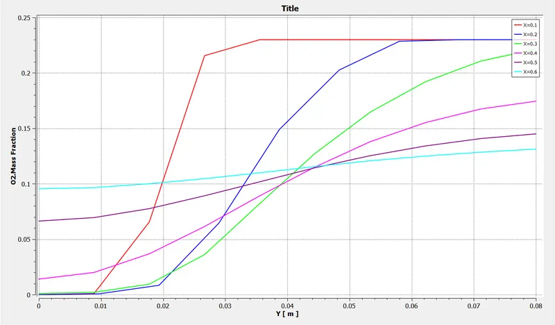
- Oxygen (O2)
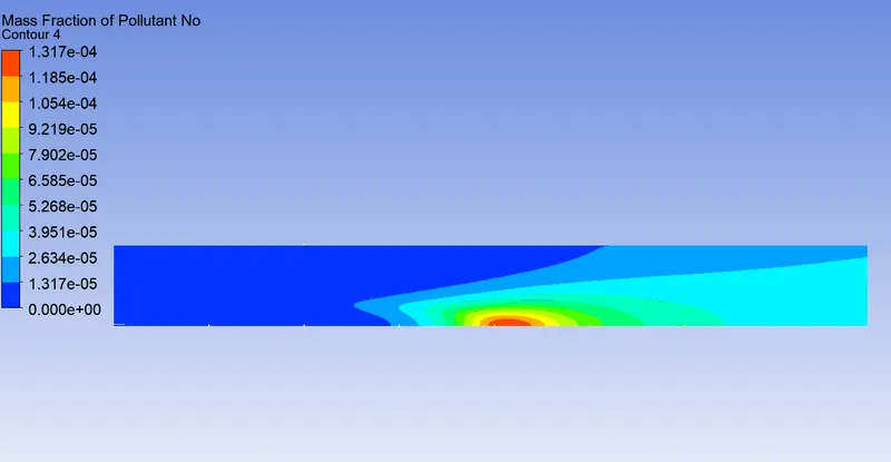
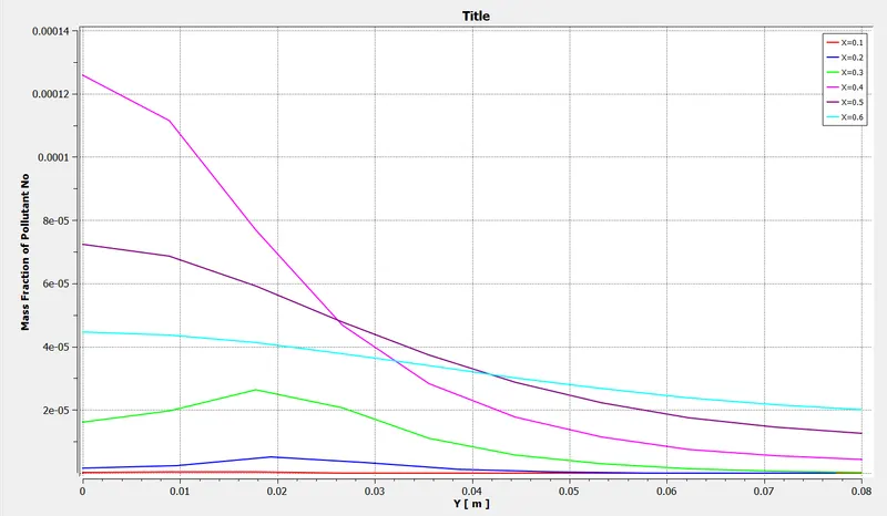
-NOx Formation
-Soot Formation
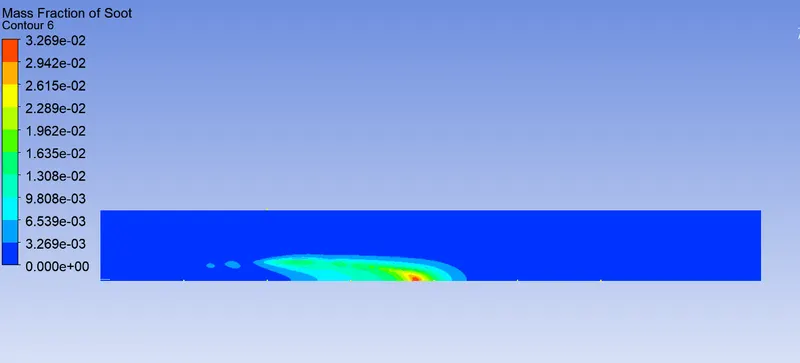
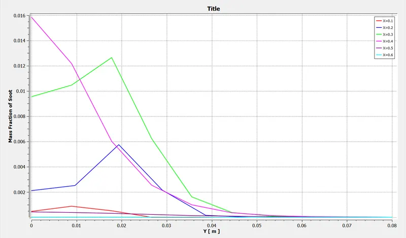
25% H20 in Air fuel Mixture
a) CH4 Mass fraction
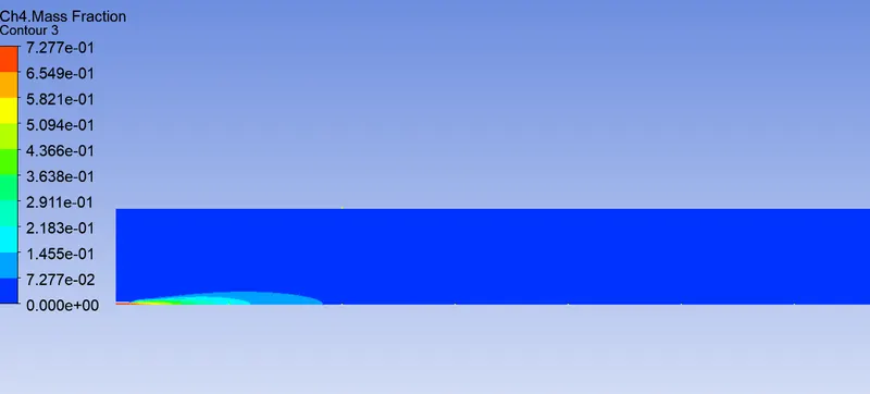
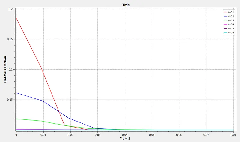
b) CO2 Mass Fraction
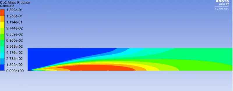
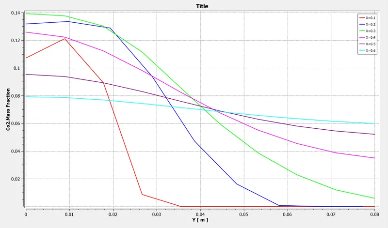
- H20
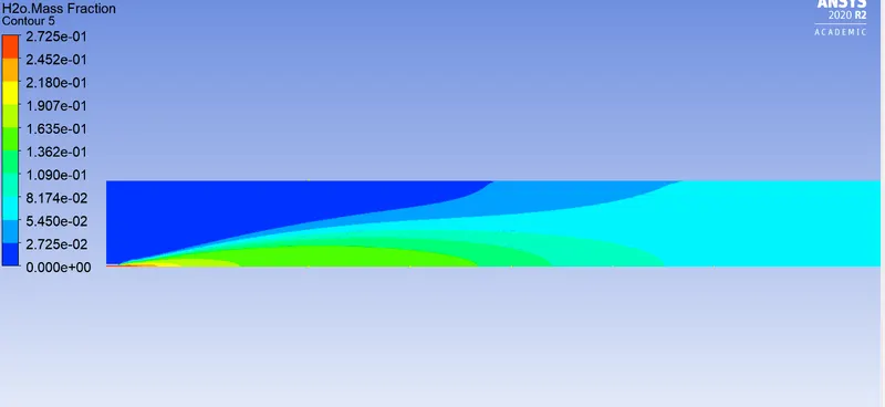
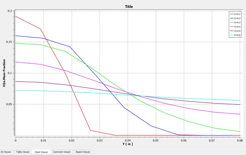
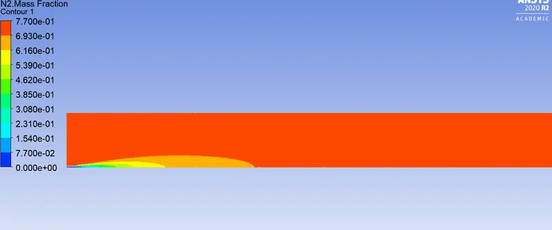
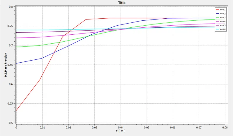
- Nitrogen (N2)
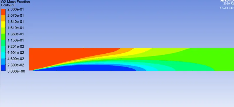
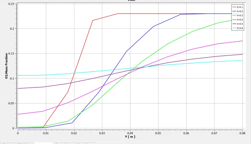
- Oxygen (O2)
-NOx Formation
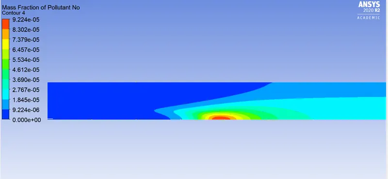
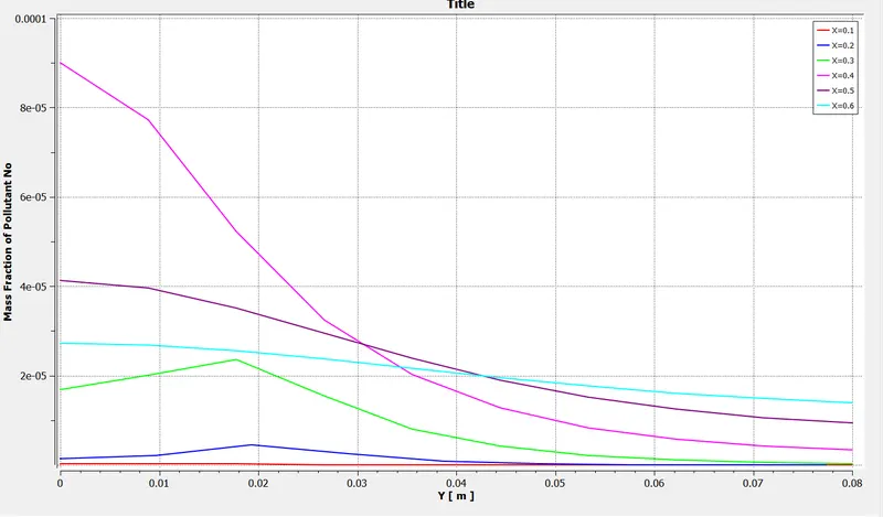
-Soot Formation
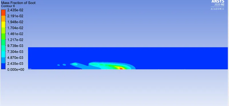
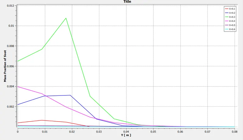
30% H20 in fuel Mixture
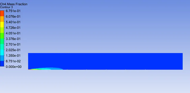
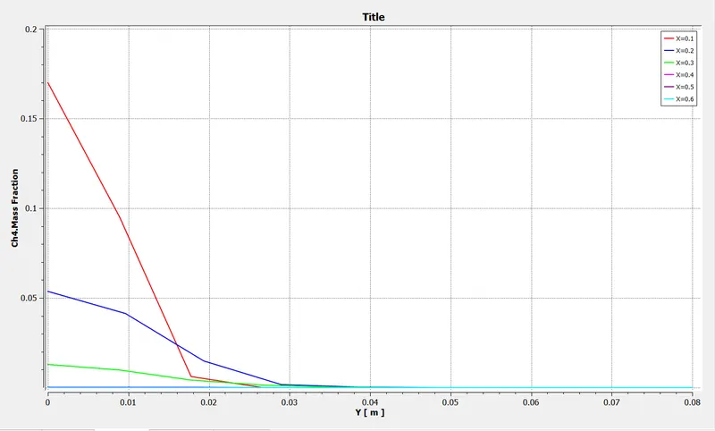
a) CH4 Mass fraction
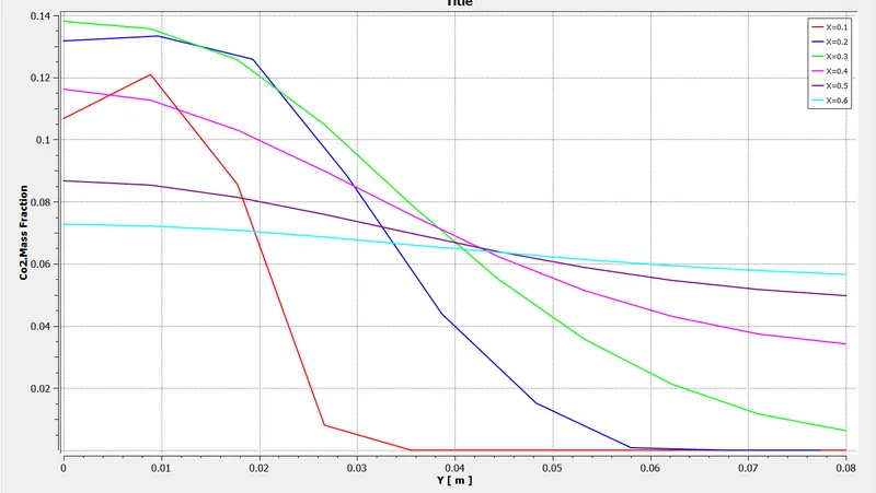
b) CO2 Mass Fraction

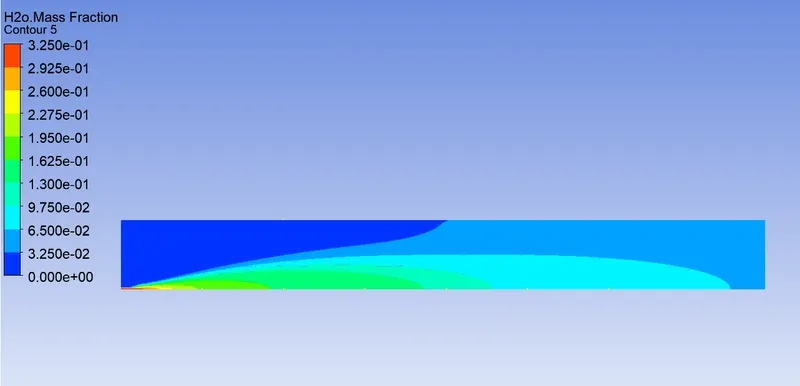
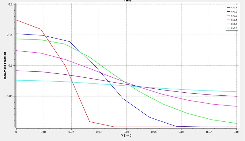
- H20
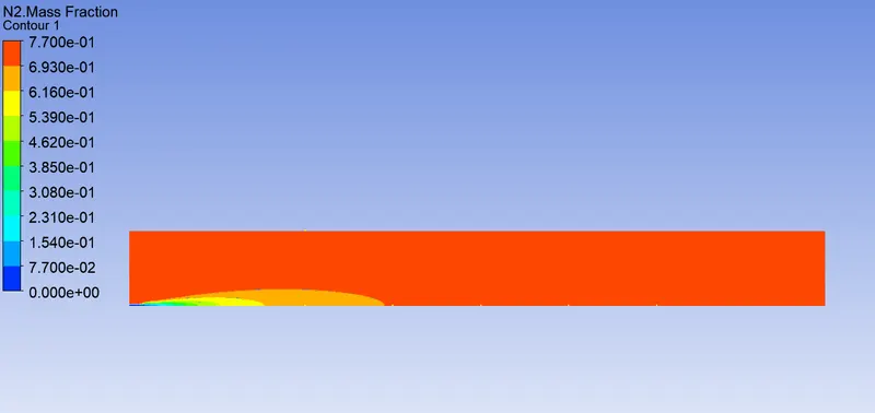
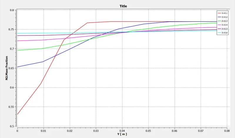
- Nitrogen (N2)
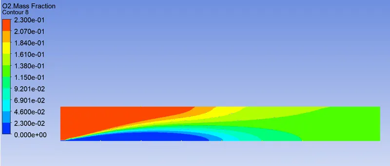
- Oxygen (O2)
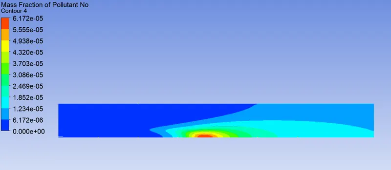
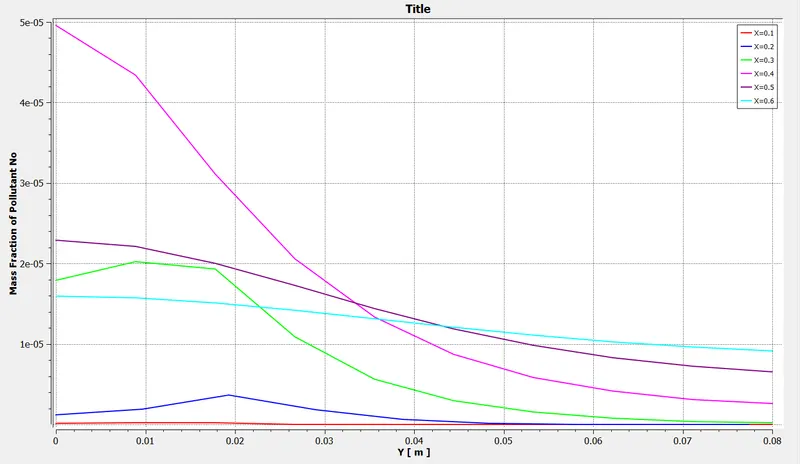
-NOx Formation
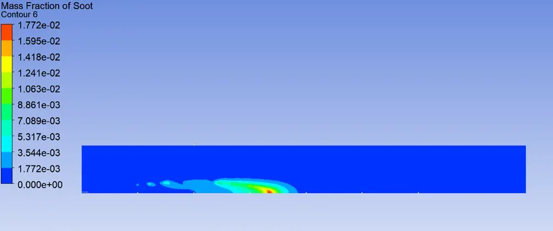
-Soot Formation
Comparison of N0X for Different Cases
0% H20 in air Fuel Mixture
0% H20
5% H20 in air Fuel Mixture
5% H20
10% H20 in air Fuel Mixture
10% H20
15% H20 in air Fuel Mixture
15% H20
20% H20 in air Fuel Mixture
20 % H20
25% H20 in air Fuel Mixture
25% H20
30% H20 in air Fuel Mixture
30% H20
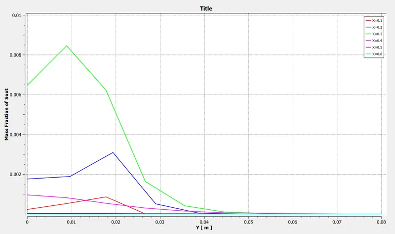
Comaparison of Soot for Different Cases
0% H20
5%H20
10% H20
15%H20
20% H20
25% H20
30% H20
Results:- Addition of water to fuel mixture reduces the magnitude of pollutant emission as can be observed from the above plots. Increasing water content aids in acheiving a more complete combustion thereby reducing quantity of pollutants.