Week 10 - Simulating Combustion of Natural Gas.
Aim: Combustion Simulation of Natural gas inside a Burner using ANSYS FLUENT.
Objective:
-
Part 1
1) Perform a combustion simulation and plot the variation of mass fraction of different species in the simulation using a line probe at different locations.
2) Set up a NOx and soot model to observe NOx emissions and soot formation.
-
Part 2
1) Add water content in the fuel from 5% to 30% by mole.
2) Provide necessary plots and contours from the CFD results.
Introduction:
- Modelling a combustion reaction in software is difficult because the species involved in the reaction and their products must be considered. The combustion CFD model includes chemical kinetics as well as a reacting flow mixture environment. When it comes to chemical kinetics, it is also critical to have a well-defined physical model with simulation to get the most out of the process. The computational fluid dynamics of the combustion model should be capable of providing information on species concentration, volumetric generation or diffusion rate, and changes in system parameters such as enthalpy, temperature, and mixture density. A similar model should be adequate for solving general transport equations for fluid flows and heat transfer, as well as additional combustion chemistry equations.
- The combustion process is defined as a chemical reaction in which a hydrocarbon fuel reacts with an oxidant to form products and release energy in the form of heat. As an essential component of various engineering applications such as internal combustion engines, furnaces, and power station combustors, combustion manifests itself as a broad domain during the design, analysis, and performance characteristics stages of the aforementioned applications. Proper physical modelling is required to solve complex equations from chemical kinetics and yield information about the reaction mechanism. The combustion process is simulated in this project using the CFD software ANSYS fluent. When combustion is incomplete, various pollutants are produced, including carbon dioxide, carbon monoxide, and lead.
- The formation of pollutants from NOx emission, which primarily consists of No, No2, N2o, and soot formation, which is a mass of impure carbon particles, is simulated in this project, and the variation of the mass fraction of pollutants from NOx emission and soot formation with the addition of water into the fuel is studied.
Natural gas combustion reaction:

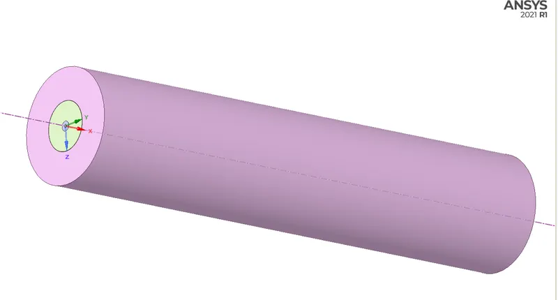
Geometric model of the given combustion model:
- 2D axisymmetric diagram of combuster consists of Air inlet and fuel inlet.
2D section Front View :

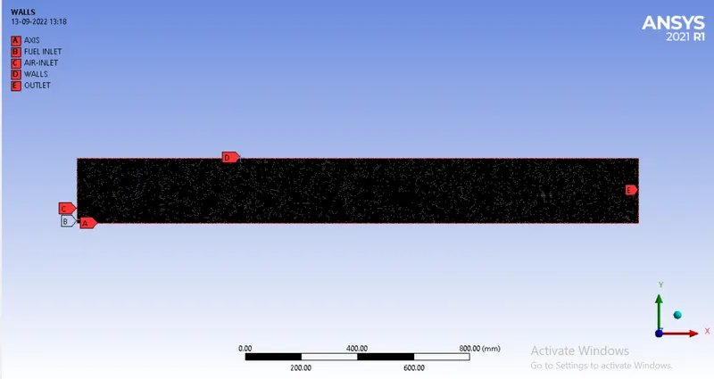
Meshing & Named Selection:
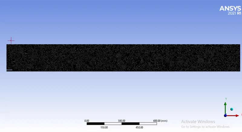
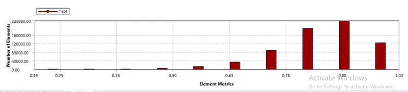
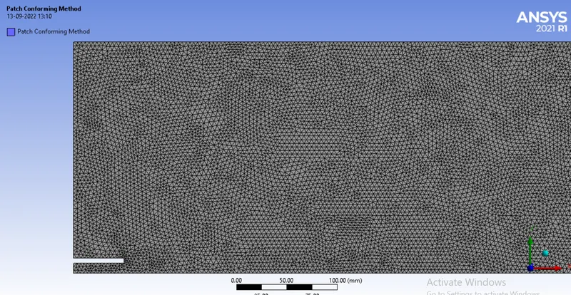
- As the geometry is 2D in nature, the number of elements required as compared to the 3D model will be less. The number of cells in the gap is provided as 3 and the element size of 5 mm is used for the whole geometry.
- Mesh Statistics:

- Naming Selection:
SETUP & SOLUTION:
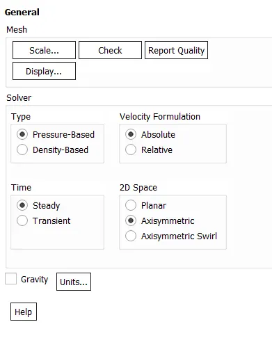
- The general setup required for simulation is the pressure-based steady-state approach for the problem.
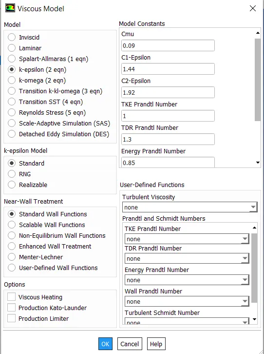
- Here the k-epsilon turbulent model with standard wall function is used as input for the flow phenomenon. As per the problem description, the velocity of air is just 0.5m/sec whereas fuel velocity is 80m/sec. Considering Reynolds number it is higher to the side and because K and epsilon are proportional reaction rate ‘omega’ it is required to have the k-epsilon model.
-
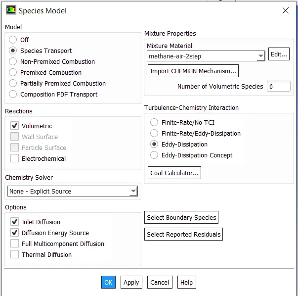
The mixture model which is used for simulamethane-airthane-air-2step’ severalnumber of volumetric species are six i.e. CO2, H2O, CH4, N2, O2 and CO. As stated earlier this model is governed by the effect of turbulence hence Eddy dissipation turbulence-chemistry interaction is selected.
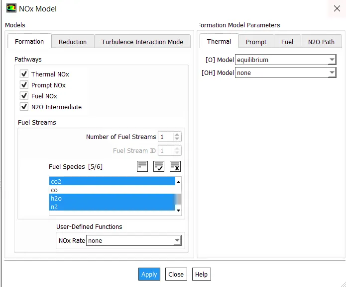
- NOx and soot models are being configured similarly to species models. As previously discussed, NOx can be produced as a result of high temperatures and a rich fuel mixture; therefore, all pathways that can track NOx generation are activated for the simulation.
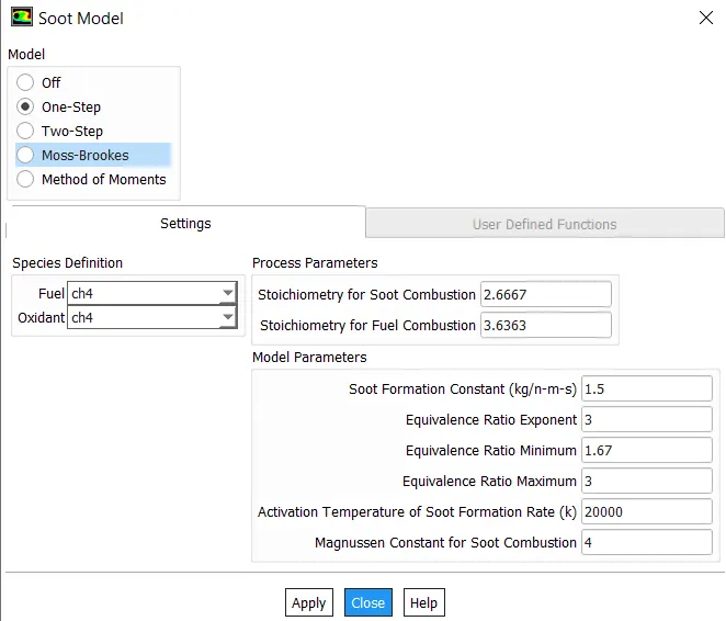
- Similarly, the soot model is enabled, with a one-step soot model used to track soot generation during the combustion process.
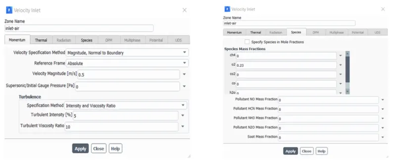
- This simulation's boundary conditions are velocity inlet and pressure outlet with an axis for Axi-symmetric condition. For this simulation, there are two inlets. The first velocity inlet is for air that is moving at 0.5m/sec inside the burner. The air enters the burner at atmospheric prese and 300 k. It is necessary to provide information about how much oxygen enters the burner in the species tab of the air inlet. For the reaction, a 0.23 mass fraction of O2 is mixed with air.
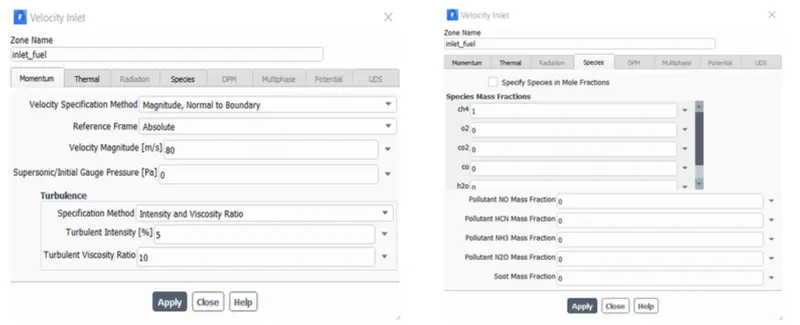
- Similarly, for the fuel inlet, the momentum boundary conditions considered are velocity inlet with the value of 80m/sec. The fuel is also entering at atmospheric pressure and 300-kelvin temperature. The most important part of the fuel inlet is the specification of species for the simulation. In the species tab of fuel inlet boundary condition, the mass fraction of Fuel is defined as 1 of CH4.
SIMULATION RESULTS:
Part 1
- Baseline Mesh setup.
Part-2:
- Case 1 – Combustion simulation with Fuel = 0.95 and Water = 0.05 (5%)
- Case 2 – Combustion simulation with Fuel = 0.9 and Water = 0.1 (10%)
- Case 3 – Combustion simulation with Fuel = 0.8 and Water = 0.2 (20%)
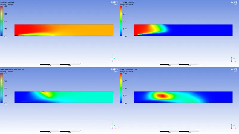
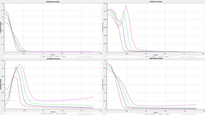
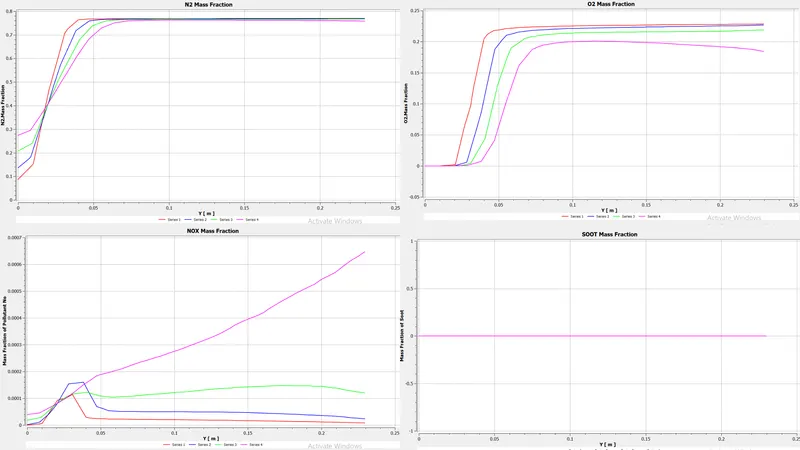
- Case 4 – Combustion simulation with Fuel = 0.7 and Water = 0.3 (30%)
Part 1: (BASELINE RESULTS):
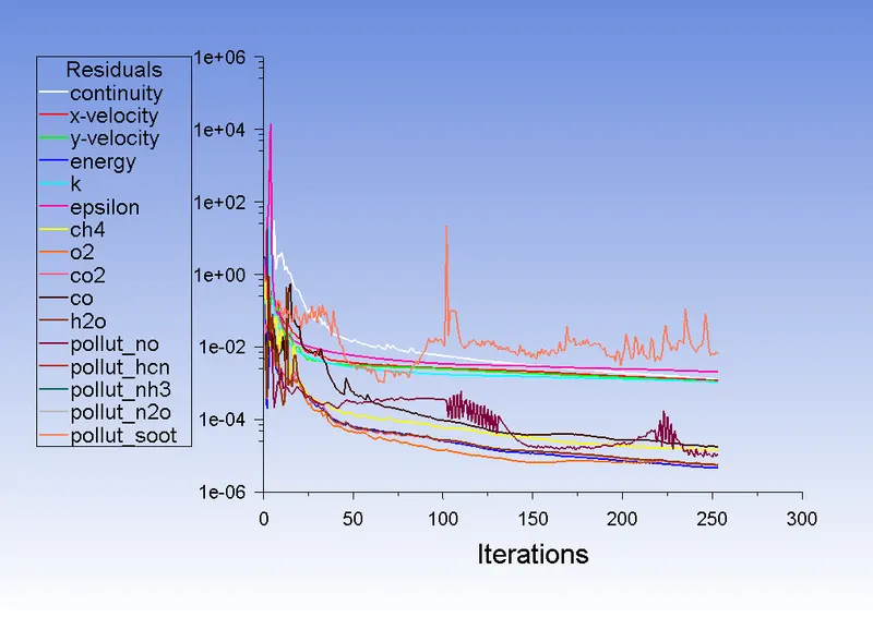
- Residual Plot:
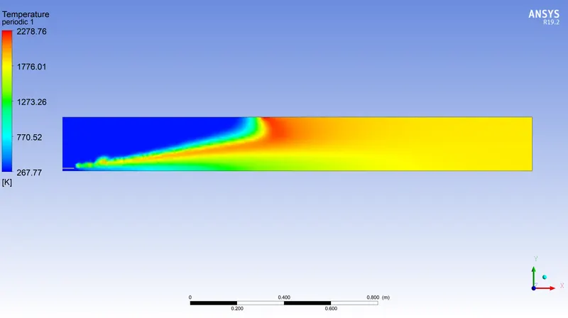
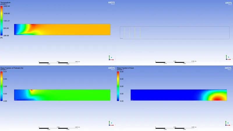
- Temperature plot:
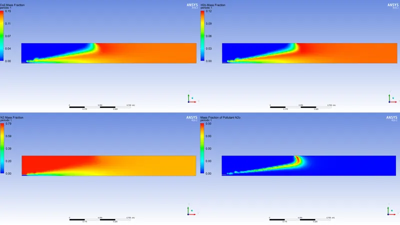
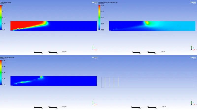
- Mass fractions:
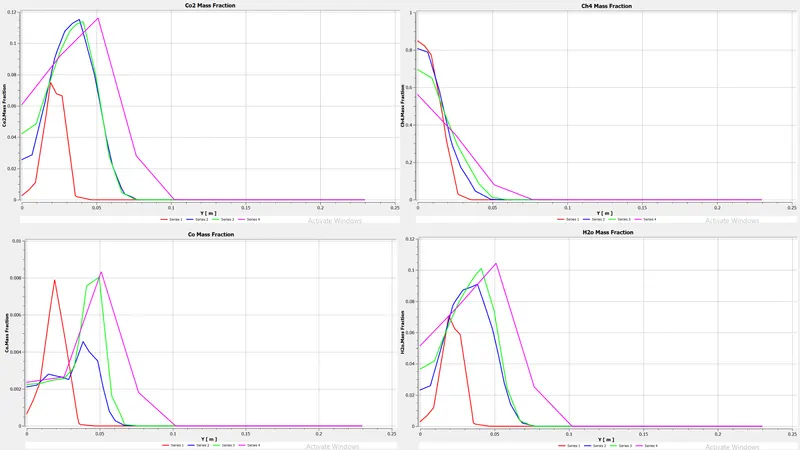
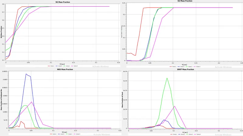
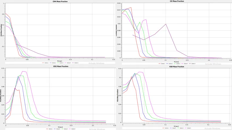
- Graphs:
Part 2: (CASE-1): Combustion simulation with Fuel = 0.95 and Water = 0.05 (5%):
-
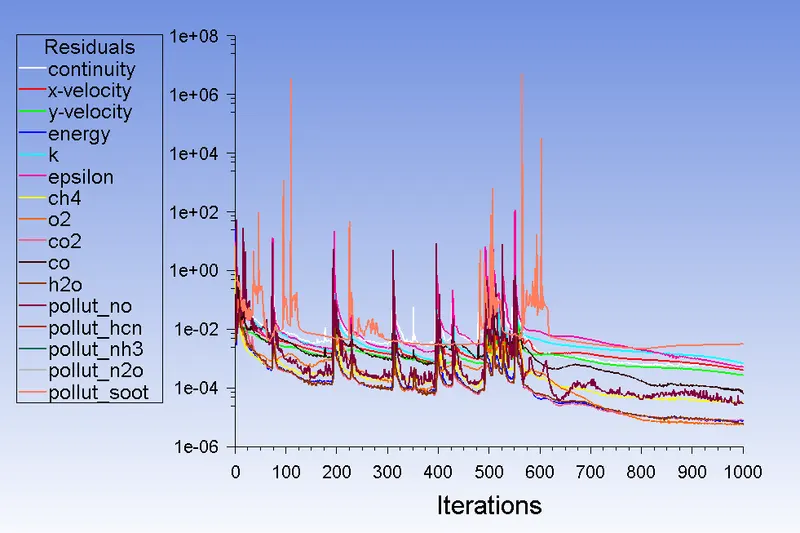
Residual Plot:
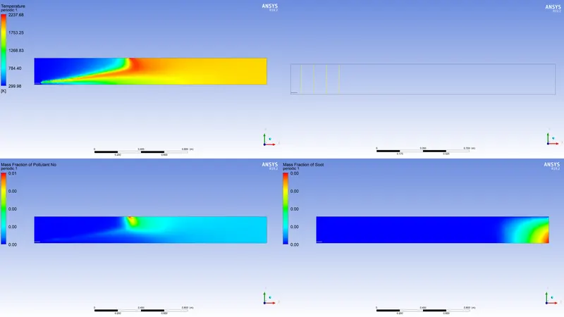
- Mass fractions:
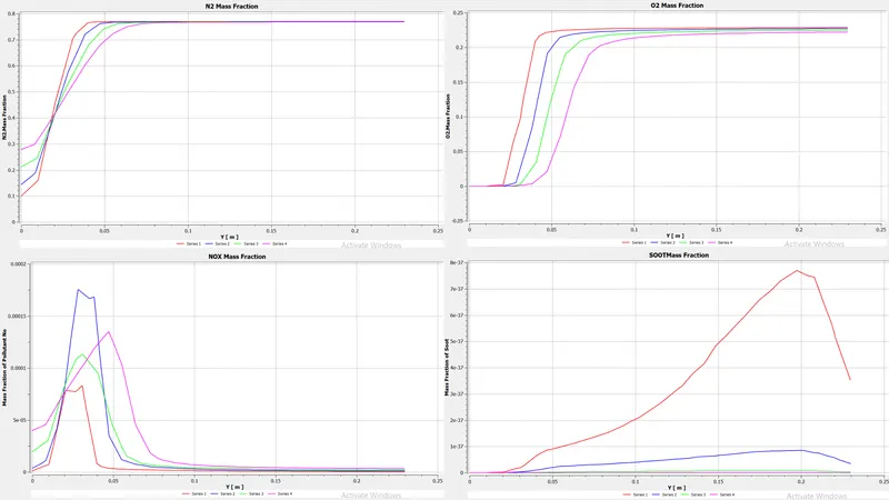
- Graphs:
Part 2: (CASE-2): Combustion simulation with Fuel = 0.9 and Water = 0.1 (10%):
-
Residual Plot:
- Mass fractions:
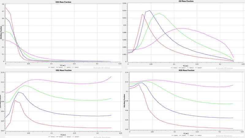
- Graphs:
Part 2: (CASE-3): Combustion simulation with Fuel = 0.8 and Water = 0.2 (20%):
-
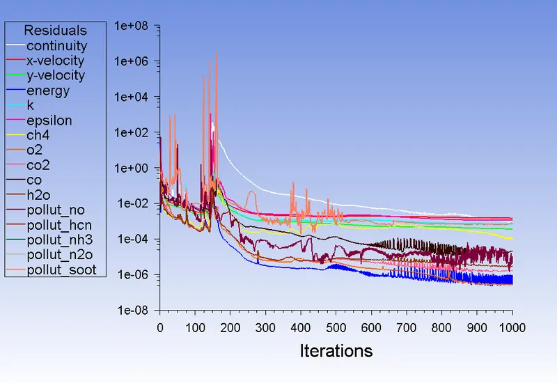
Residual Plot:
- Mass fractions:
- Graphs:
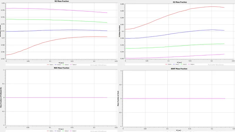
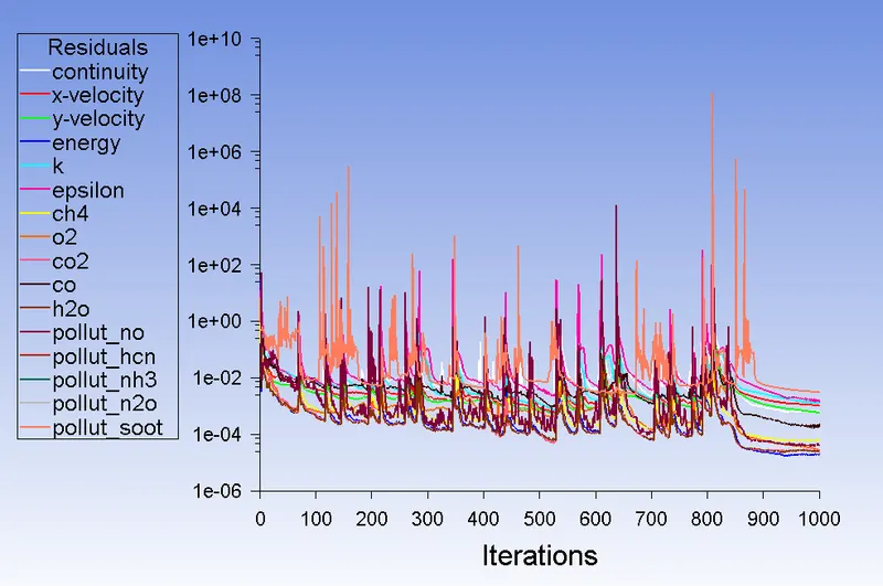
Part 2: (CASE-4): Combustion simulation with Fuel = 0.7 and Water = 0.3 (30%):
-
Residual Plot:
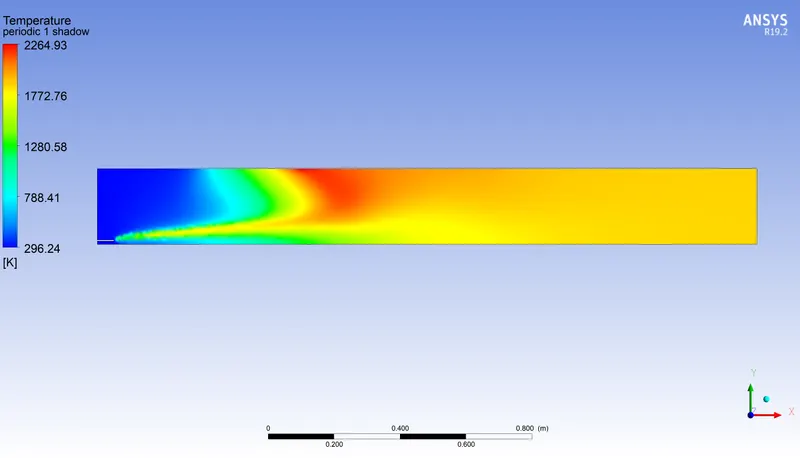
- Temperature plot:
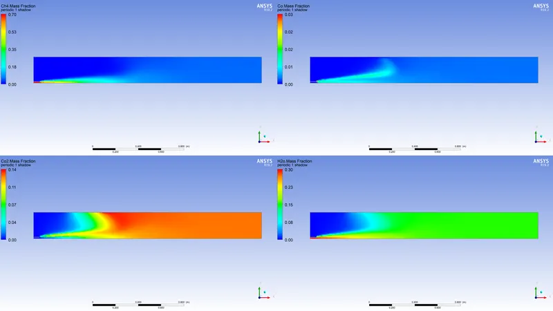
- Mass fractions:
- Graphs:
CONCLUSION:
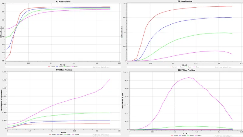
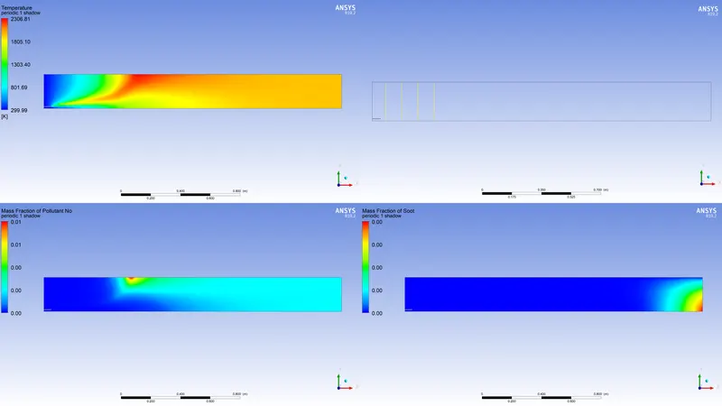
- In the baseline mesh setup in which the whole amount of CH4 is present as the fuel the amount of soot and NOx is greater as compared to other cases. Also, the maximum temperature is about 2300 K.
- In the next cases where the water is added with fuel in respect of 5% to 30%, there is a reduction of NOx by a certain amount.
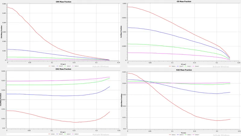
- Similar to NOx, from the result table it can be seen that the mass fraction of CO2 is also decreasing as the water percentage is increasing. The Mass fraction of N2 is almost constant for all the cases which means the flame instability for the burner is almost constant for all the cases of combustion.
- In the case of soot formation, it can see that the mass fraction of soot is decreasing for cases 1 and 2 but for cases 3 and 4 it has increased. After checking the Mass fraction of the soot contour for all the cases, it is evident that soot formation from cases 1 to 4 is unbalanced but the amount of soot formation is significantly lowered for cases 3 and 4. It is seen that from cases 3 and 4 contours of mass fraction of soot, the formation of soot is nearer to the outlet of the burner which is a common practice of soot to be deposited at the outlet.
- From the whole simulation, it concluded that providing water with fuel will reduce harmful exhaust emissions such as NOx and Soot.
REFERENCE:
- https://www.sciencedirect.com/science/article/pii/S1876610217337724
- https://link.springer.com/article/10.1007/s00773-015-0303-8
- https://www.sciencedirect.com/science/article/pii/S1876610217337724
- https://www.afs.enea.it/project/neptunius/docs/fluent/html/th/node212.htm