Week 3.2 - 2R Robotic Arm Challenge
Aim: To write a program using Matlab to simulate the forward kinematics of a 2R Robotic Arm.
Objective:
-
Create a program to simulate the forward kinematics of a 2R robotic arm.
-
To create a motion picture or animation using the program's plots.
Theory:
-
In this project, we are going to deal with the linkage known as the Forward Kinematics of a 2R Robotic arm in our project, and we're using the basic robotic arms to accomplish that (where 2R means 2-rotating Link i.e 2 is a number of links and R is rotation). Link-1 is aligned at (X0, Y0) and makes an angle1, while Link-2 is hinged at the end of Link-1 and makes an angle2 with respect to Datum. These two links are used as a representation of a robotic arm.
FACTORS ENTAILED:
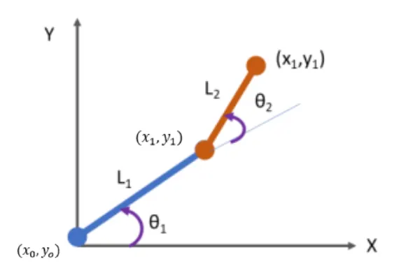
- Let, L1 and L2 represent the lengths of links 1 and 2, respectively.
- Let, θ1 be the angle that link 1 makes with the horizontal.
- Let, θ2 be the angle that link 2 makes with the horizontal.
- Let, the starting and ending coordinates of link-1, respectively (x0, y0) and (x1, y1)
- Let, the starting and ending coordinates of link-2, respectively (x1, y1) and (x2, y2)
Code Explanation:
- Used a programming language online Matlab
- Starting the program by using commands
- Providing an input variable like predetermining the length/values of the robotic arms.
- Adding the Cr (compression ratio) value as a specific digit.
- Calculating the position of Link-1. From the fixed Support, the initial value of X and Y for the Link-1 (X0, Y0) and the final value is (X1, Y1)
- Calculating the position of the Link-2. For Link-2 starting point is the Ending point if the Link-1 ie (X1, Y1) and the Ending point is (X2, Y2)
- Providing the values for theta1 and theta2 using the linspace command.where, theta = 0 to 90 degree for 14 values.
- Providing the equation for the x1,y1,x2, and y2 for defining the coordinates of both robotic arms.
- Providing the axis number and plotting all coordinate values.
- All figures are assigned to a variable M_, one at a time using compression ratio.
- Use the pause command to make the plot authentic look.
- Ended the 'for' loop twice.
- using the movie command to combine all the plotted images saved in the M_ file to create a movie.
- Finally, the movie is saved in the .avi format.
Program:
% Program for 2R Robotic Arm
clear all
close all
clc
%Inputs
L1=1;
L2=0.5;
theta1=linspace (0,90,14);
theta2=linspace (0,90,14);
ct=1;

for i=1:length(theta1)
    THETA1=theta1(i);
    for j=1:length(theta2)
        THETA2=theta2(j);
    x0=0;
    y0=0;
    x1=L1*cosd(THETA1);
    y1=L1*sind(THETA1);
    x2=x1+L2*cosd(THETA2);
    y2=y1+L2*sind(THETA2);
    %plotting
    plot([x0,x1],[y0,y1], [x1,x2],[y1,y2],'linewidth',2);
    axis([-0.1 1.5 0 1.5]);
    pause (0.1)
    M(ct)=getframe(gcf);
    ct=ct+1;
    end
end

movie(M)
Videofile=VideoWriter('Robotic_arm.avi','Uncompressed AVI');
open(Videofile)
writeVideo(Videofile,M)
Close(videofile)
Errors & Command window:
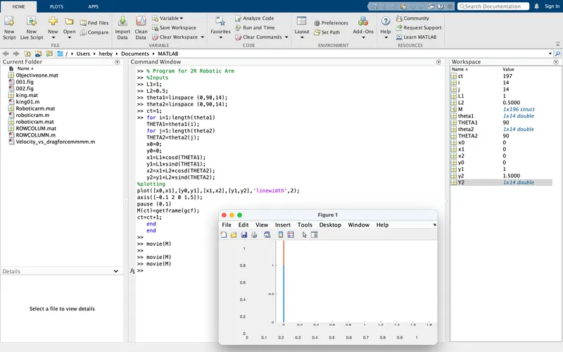
- No Errors were found during execution.
Result & Conclusion:
- Hence, the 2R robotic arm is simulated by using Matlab programming, and the movie from the plots obtained from the program is also created.
- The below link is given for the program output movie for a 2R robotic arm.