Week 10 - Simulating Combustion of Natural Gas.
REPORT
Combustion of Natural Gas
AIM
- Combustion simulation of natural gas on a combustor model using ANSYS Fluent.
ABSTRACT
This study presents a systematic investigation of the strategies required for modelling soot when performing CFD simulations of turbulent flames. The systematic approximation is used in the combustion model and through the species model product’s mass fraction at different locations using line probes is seen. Special attention has been paid to the allowed amount of nitrogen oxides and sulphur oxides in the exhaust gas. The mechanism of decreasing nitrogen oxides in the exhaust gas employing water supply into the combustion chamber of the combustor model is examined. Advantages and disadvantages of supplying water into the combustion chambers of the model have been shown together with the comparison of the range of changes in their construction.
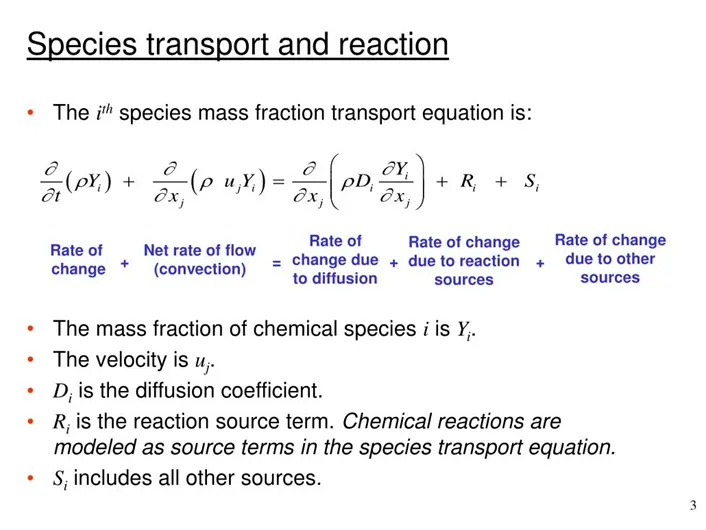
Equations solved
- Mass
- Momentum
- Species Transport Equation
Source terms are computed using the combustion model
THEORY
Combustion
Combustion is the high-temperature exothermic redox chemical reaction in which a hydrocarbon fuel reacts with an oxidant to form products, accompanied by the release of energy in the form of heat. Combustion is often a complicated sequence of elementary radical reactions. While the activation energy must be overcome to initial combustion, the heat from a flame may provide enough energy to make the reaction self-sustaining.
Complete combustion is stoichiometric concerning the fuel, where there is no remaining fuel, and ideally, no residual oxidant. Thermodynamically, the chemical equilibrium of combustion in air is overwhelmingly on the side of the products. However, complete combustion is almost impossible to achieve, since the chemical equilibrium is not necessarily reached, or may contain unburnt products such as carbon monoxide, hydrogen and even carbon (soot or ash). Thus, the produced smoke is usually toxic and contains unburned or partially oxidized products. Any combustion at high temperatures in atmospheric air, which is 78% nitrogen, will also create small amounts of several nitrogen oxides, commonly referred to as NOx, since the combustion of nitrogen is thermodynamically favoured at high, but not low temperatures.
Combustion model for CFD analysis
Combustion manifests itself as a wide domain during the design, analysis and performance characteristics stages of the above-mentioned applications. With the added complexity of chemical kinetics and achieving reacting flow mixture environment, proper modelling physics has to be incorporated during CFD simulations of combustion.
CFD modelling of combustion calls upon the proper selection and implementation of models suitable to faithfully represent the complex physical and chemical phenomenon associated with any combustion process. The model should be competent enough to deliver information related to the species concentration, their volumetric generation or destruction rate and changes in the parameters of the system like enthalpy, temperature and mixture density. The model should be capable of solving the general transport equations for fluid flow and heat transfer as well as additional equations of combustion chemistry and chemical kinetics incorporated into that as per the simulating environment desired.
Critical Considerations
The primary consideration during any general combustion process includes the process's mixing time scale and the reacting time scale elapsed. The flame type and the type of mixing of flow streams of the constituents also have to be taken into account.
The simple chemical reacting system model takes into consideration only the final concentration of species and takes into account only the global nature of the combustion process where the reaction proceeds infinitely fast as a single-step process without much stress on the detailed kinetics involved.
Types of combustion simulation in Ansys Fluent
Combustion based on Mixing
- Non-Premixed Combustion
In non-premixed combustion, fuel and oxidizer enter the reaction zone in distinct streams. It occurs during direct injection or late injection of fuel in IC engines.
An example of non-premixed combustion includes pulverized coal furnaces, diesel international combustion engines and pool fires.
- Premixed Combustion
In premixed combustion, fuel and oxidizer are mixed at the molecular level before ignition. Combustion occurs as the flame front propagates into the unburnt reactants. Examples include aspirated internal combustion engines, lean-premixed gas turbine combustors, and gas-leak explosions.
- Partially Premixed Combustion
Partially premixed combustion systems are premixed flames with non-uniform fuel-oxidizer mixtures (equivalence ratios). Such flames include premixed jets discharging into an inert atmosphere, lean premixed combustors with diffusion pilot flames and cooling air jets, and imperfectly mixed inlets.
Combustion based on Phase
- Fluid Phase (Volumetric Reactions)
Combustion takes place in the fluid region.
- Wall (Surface Reactions)
Combustion takes place on the wall or a solid surface.
- Particles (Surface Reactions)
Combustion takes place on the Lagrangian particles. The combustion of coal is an example of particle combustion.
- Porous Region
Combustion takes place in a porous region. The reaction in an after-treatment system is an example of combustion in the porous regions.
Combustion Reactions
The general reaction of combustion is given as follows:
CH4 + ar(O2 + 3.76N2) → aCO2 + bH2O + cN2
Balancing the given stoichiometric equation:
- a = 1
- 2b = 4 implies b = 2
- 2ar = 2a + b implies ar = 2
- c = 7.52*ar implies c = 15.04
The above value corresponds to the number of moles of the given species.
- Fuel
- Air
2 moles of O2 + 7.52 moles of N2
Therefore,
Mole Fraction
O2 = `2 / (2 + 7.52) = 0.21`
N2 = `7.52 / (2 + 7.52) = 0.79`
Mass Fraction
O2 = `(0.21 * 16) / (0.21 * 16) + (0.79 * 14) = 0.23`
N2 = `(0.79 * 14) / (0.21 * 16) + (0.79 * 14) = 0.77`
CASE STATEMENT
Combustion: Non-Premixed combustion
Combustion source calculation Model: Eddy Dissipation Model (Mixing based model)
Fuel Species: Methane
Fluid: Air (a mixture of oxygen and nitrogen)
At inlet
- Velocity of air: 0.5 m/s
- Velocity of fuel: 80 m/s
CASE 1: Combustion simulation to fetch a mass fraction of different species like CO2, H2O, CH4, N2, O2, NOx and SOOT formation.
CASE 2: Adding water in fuel from 5% to 30% by mole and observing the results of NOx emission and SOOT formation.
NOTE
- For fuel, methane-air 2 step as a mixture is used as it allows adding water to the fuel or air.
- For Soot formation, a one-step Soot Model is used.
PROCEDURE TO SETUP THE CASE
SpaceClaim
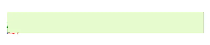
- 2D axisymmetric geometry
- Combine components into a single body
- Generate three planes on the respective axis
- Generate the quadrant portion of the 3D geometry using the split body command.
- Copy and save the resulted 2D final geometry for simulation use.
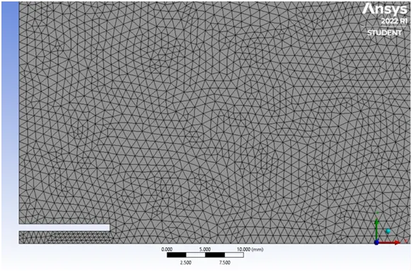
Mesh
- Element size: 1 mm
- All Triangles Method
- Capture Proximity
- Statistics
Nodes: 73670
Elements: 145540
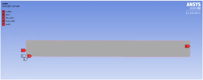
- Boundaries for the geometry are generated using name selection.
- Axis
- Fuel-inlet
- Air-inlet
- Walls
- Outlet
Mesh
Name Selection
Simulation Setup
General Settings
Solver
- Type – Pressure-based
- Time – Steady State
- 2D Space – Axisymmetric
Energy Model ON
Viscous Model
- Turbulence
- k-epsilon (2 equation)
- Model – Standard
- Near Wall Treatment – Standard Wall Functions
Note: The choice for the k-epsilon viscous model is made according to the characteristic of the flow i.e. turbulent flow. For Reynolds numbers about 2000 and more, the flow becomes turbulent.
Species Model
- Model: Species Transport
- Reactions: Volumetric
- Options
- Inlet Diffusion
- Diffusion Energy Source
- Mixture Properties
- Mixture Material
Methane-air-2step
- Turbulence-Chemistry Interaction
Eddy-Dissipation
NOx Model
- Pathways
- Thermal NOx
- Prompt NOx
- Fuel NOx
- N2O Intermediate
- Fuel species
- CH4
- O2
- CO2
- H2O
- N2
Soot Model
- Model: One-Step
Boundary Conditions
- Air-Inlet
- Type: Velocity-Inlet
- Velocity: 0.5 m/s
- Thermal Temperature: 300K
- Species Mass Fraction
- CH4 – 0
- O2 – 0.23
- CO2 – 0
- H2O – 0
- Fuel-Inlet
- Type: Velocity-Inlet
- Velocity: 80 m/s
- Thermal Temperature: 300K
- Species Mass Fraction
- CH4 – 1
- O2 – 0
- CO2 – 0
- H2O – 0
- Outlet
- Type: Pressure-Outlet
- Gauge pressure – zero Pa
Solution
- Use definitions to plot important parameters.
- Define necessary contours for tracking the result.
- Method: hybrid Initialization
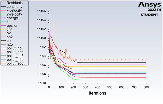
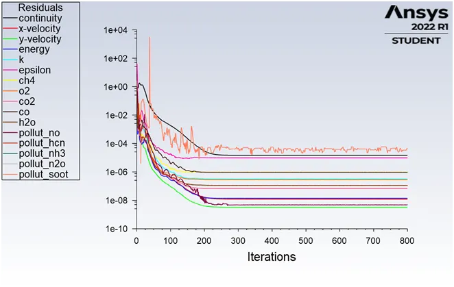
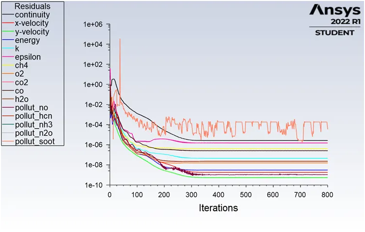
- Calculating with 800 iterations
CFD Post
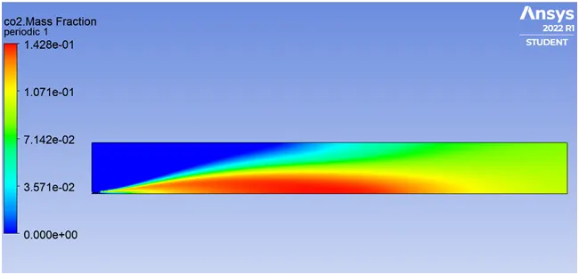
- We create contours for temperature, CO2, H2O, CH4, N2, O2, NO, N2O, and SOOT.
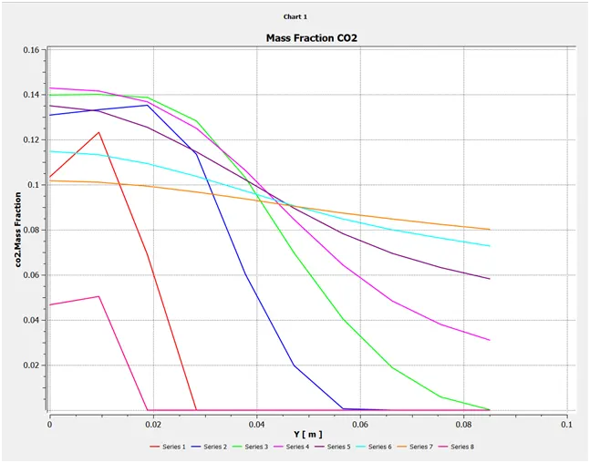
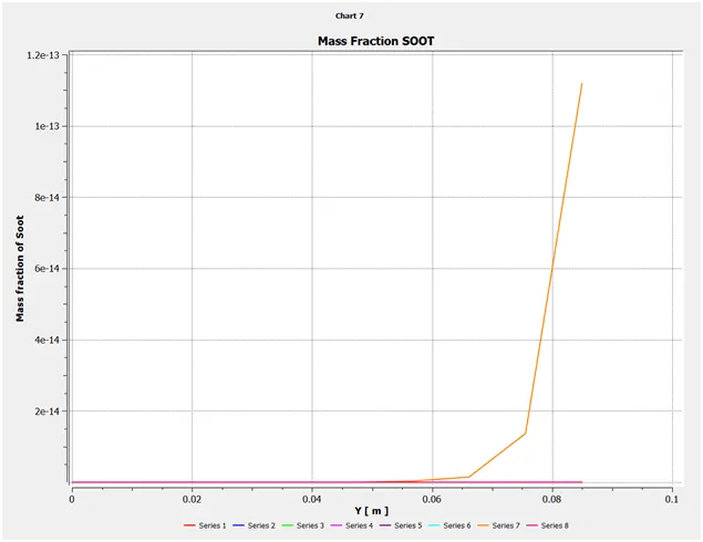
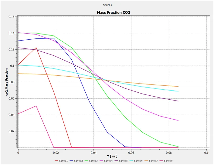
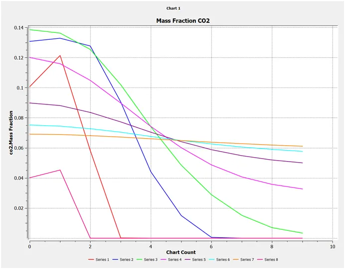
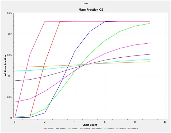
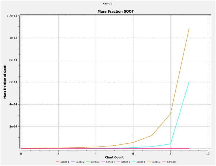
Line Probes
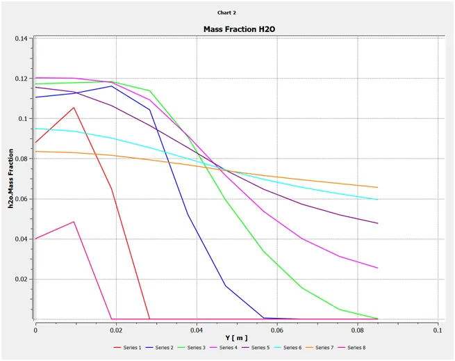
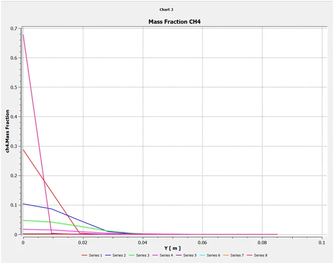
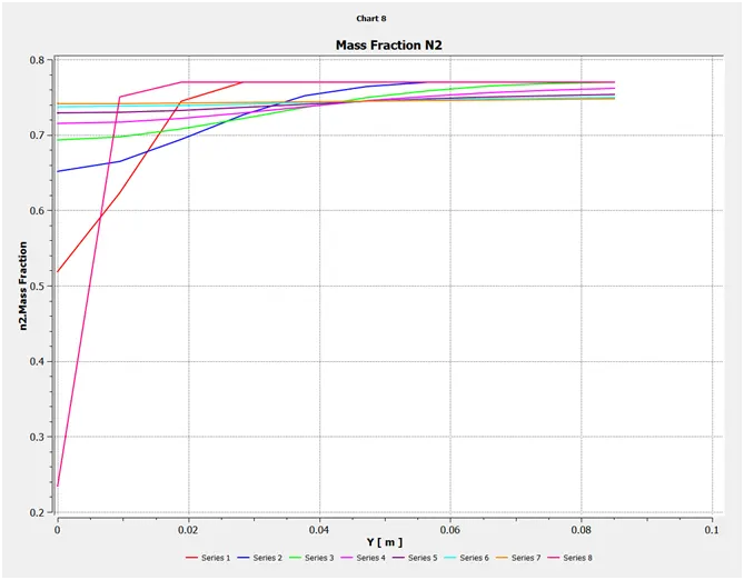
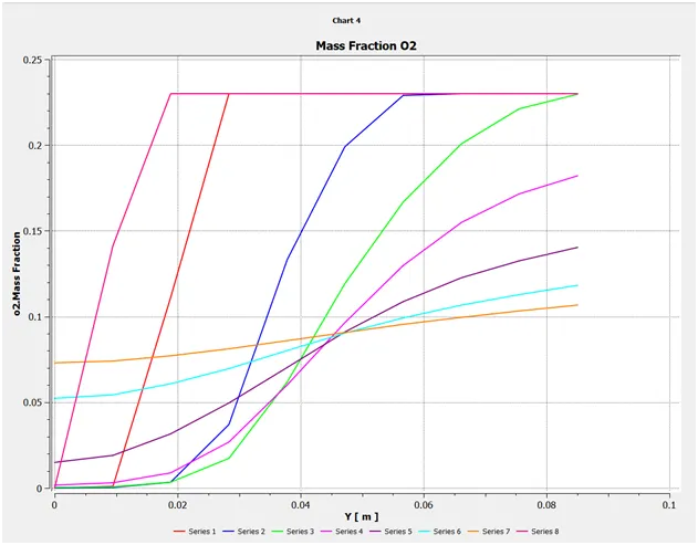
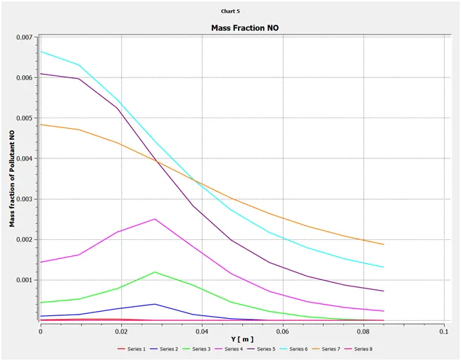
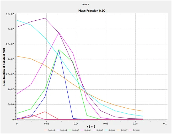
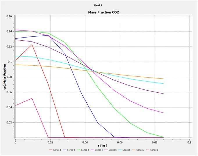
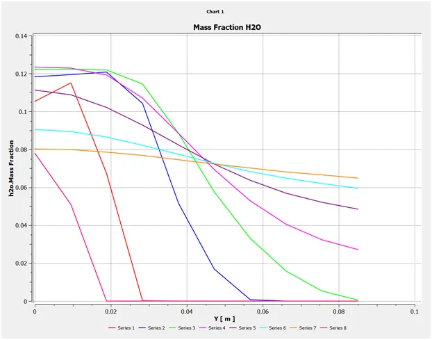
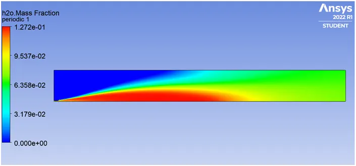
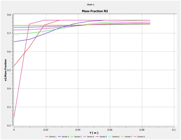
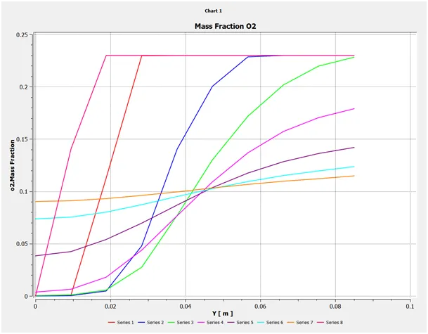
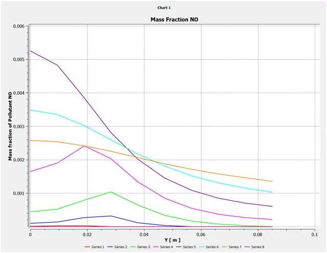
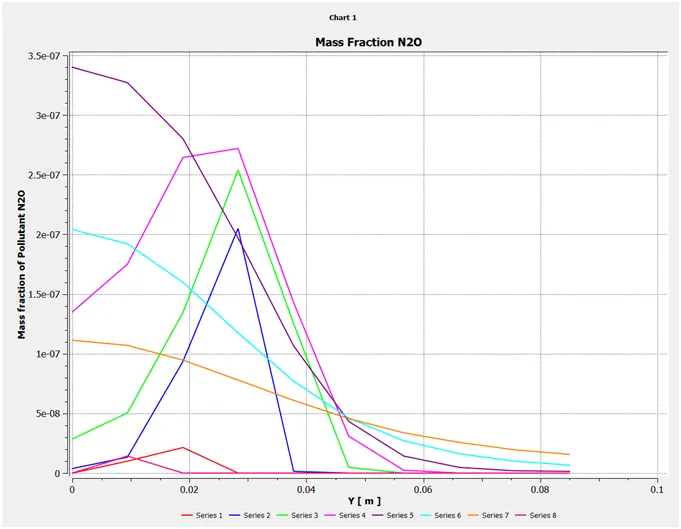
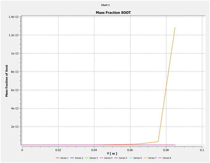
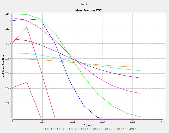
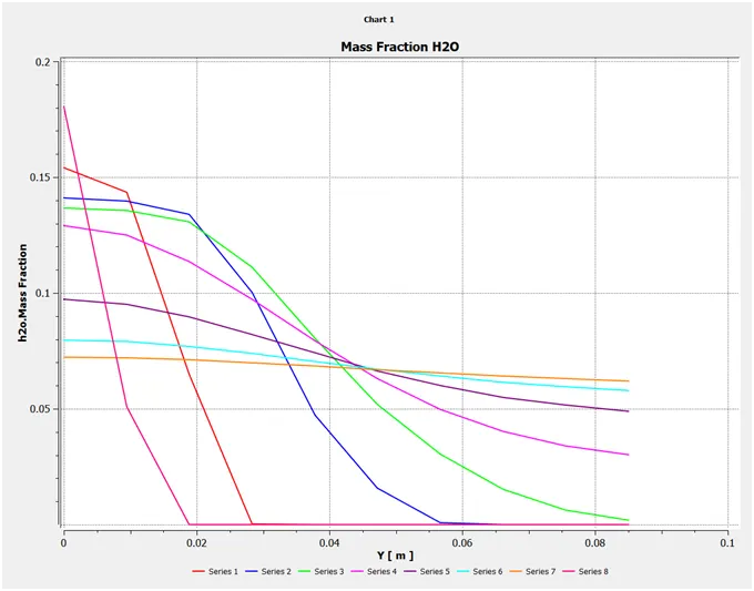
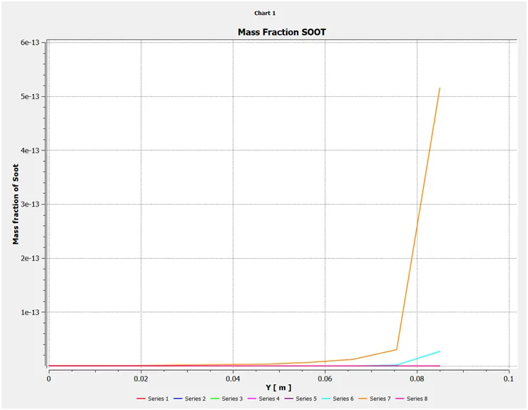
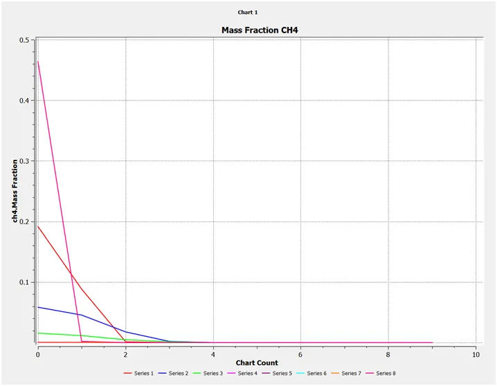
Line probes at different locations from left to the right meter can be created using the Two Point Method
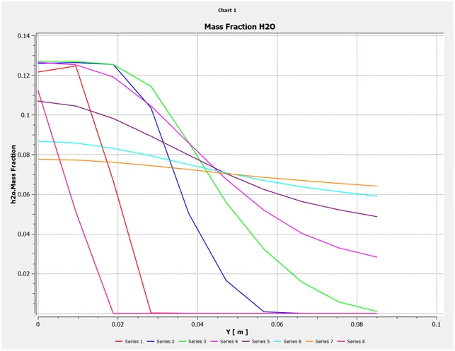
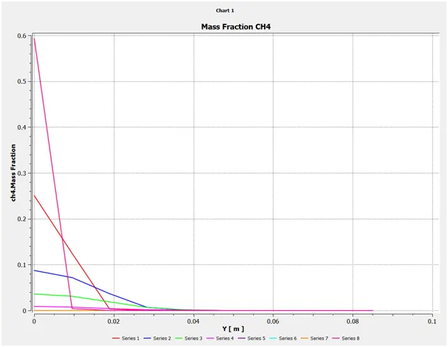
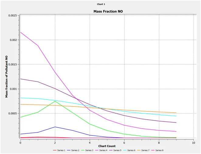
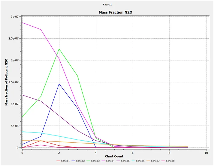
Series 1 Line 1 (0.1, 0) (0.1, 0.850133)
Series 2 Line 2 (0.2, 0) (0.2, 0.850133)
Series 3 Line 3 (0.3,0) (0.3, 0.850133)
Series 4 Line 4 (0.4, 0) (0.4, 0.850133)
Series 5 Line 5 (0.5, 0) (0.5, 0.850133)
Series 6 Line 6 (0.6, 0) (0.6, 0.850133)
Series 7 Line 7 (0.7, 0) (0.7, 0.850133)
Series 8 Line 8 (0.05, 0) (0.05, 0.850133)

OUTPUT
PART 1
Residual
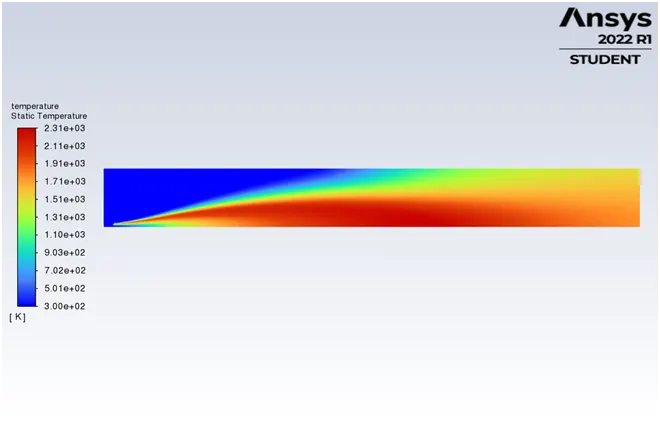
Temperature Contour
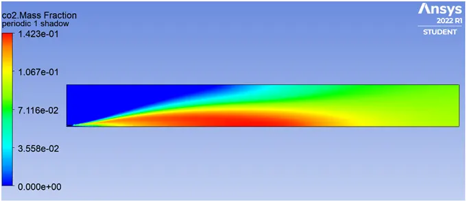
CO2 Mass Fraction
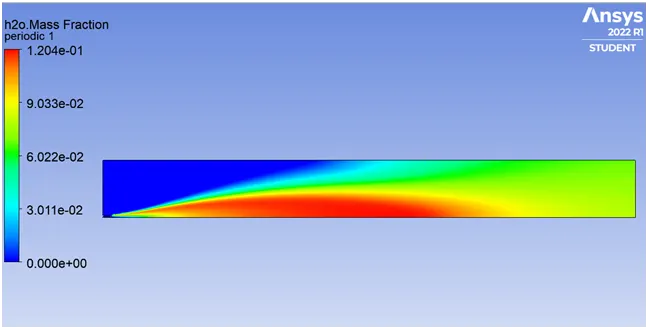
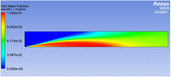
H2O Mass Fraction
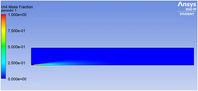
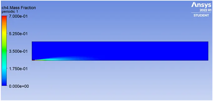
CH4 Mass Fraction
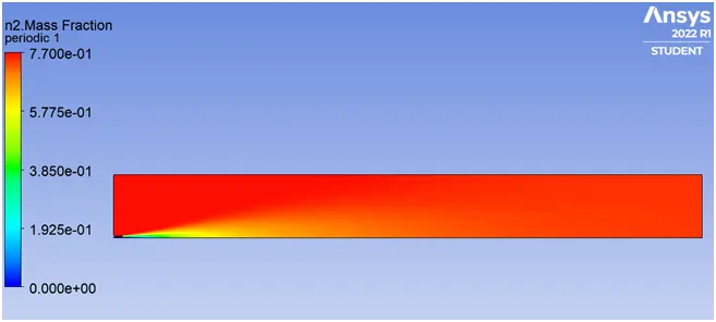
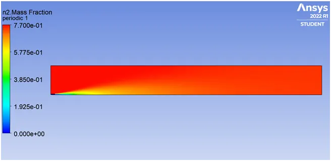
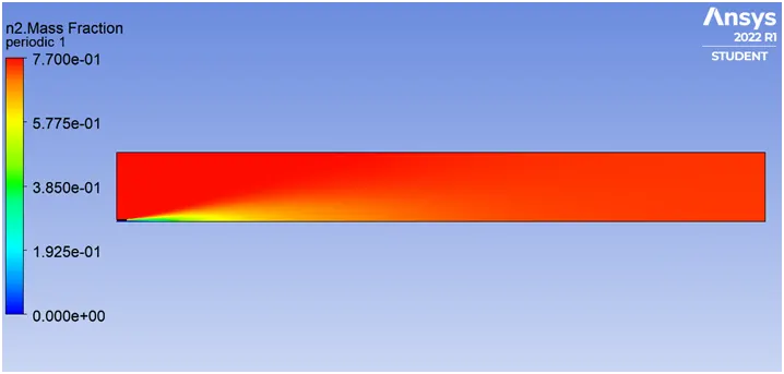
N2 Mass Fraction
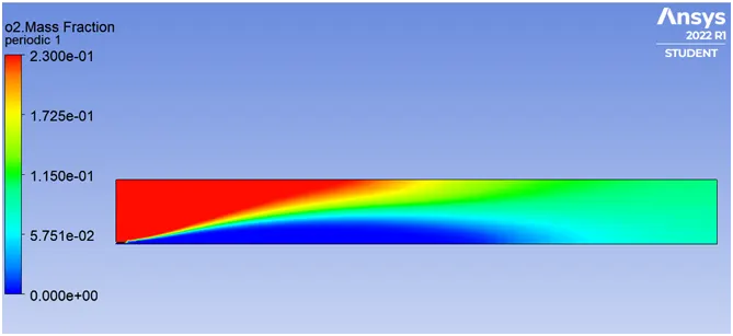
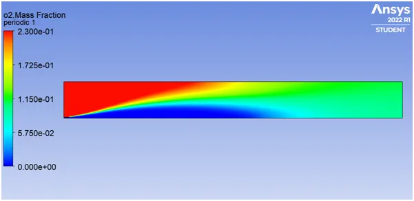
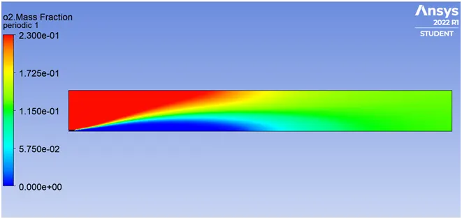
O2 Mass Fraction
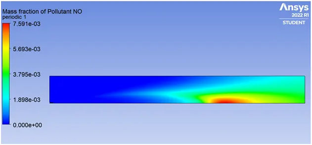
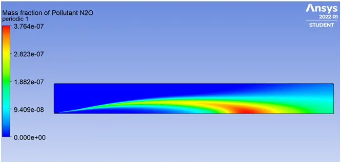
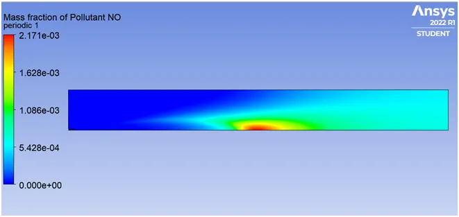
The contour of NOx Mass Fraction:
NO
N2O
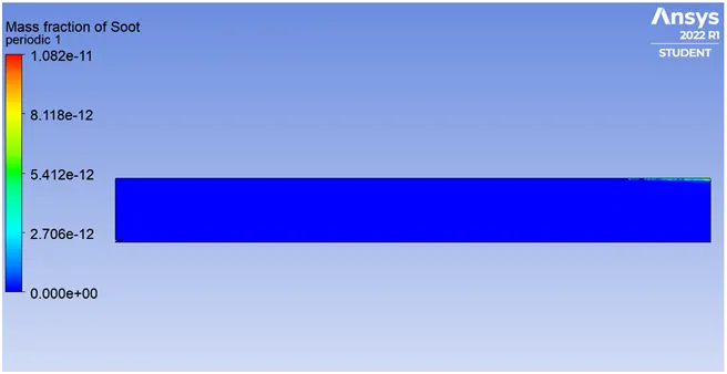
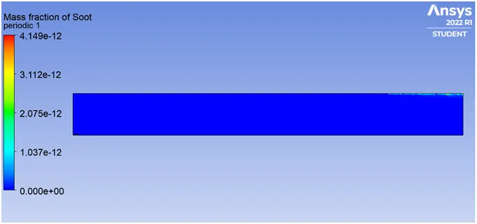
Contours of SOOT Mass Fraction
Part 2
CASE 1
95% CH4 AND 5% H2O
Residuals
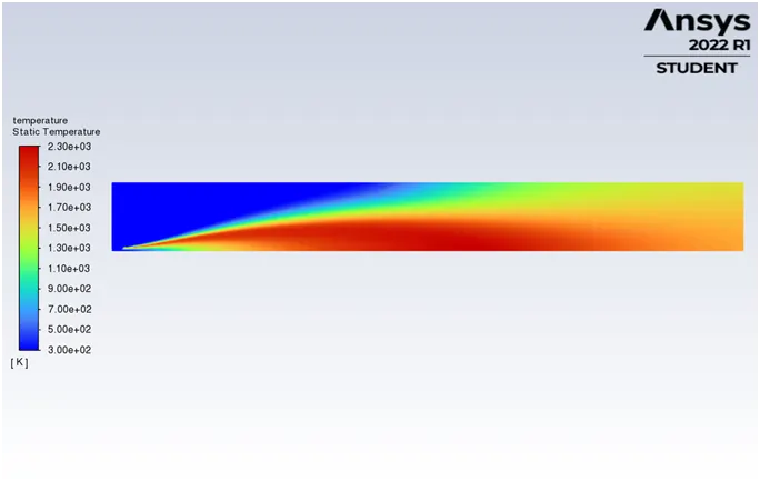
Temperature Contour
CO2 Mass Fraction
H2O Mass Fraction
CH4 Mass Fraction
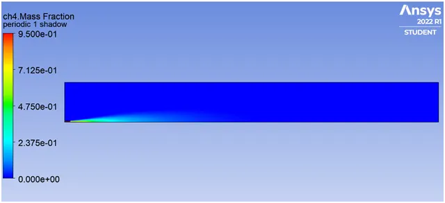
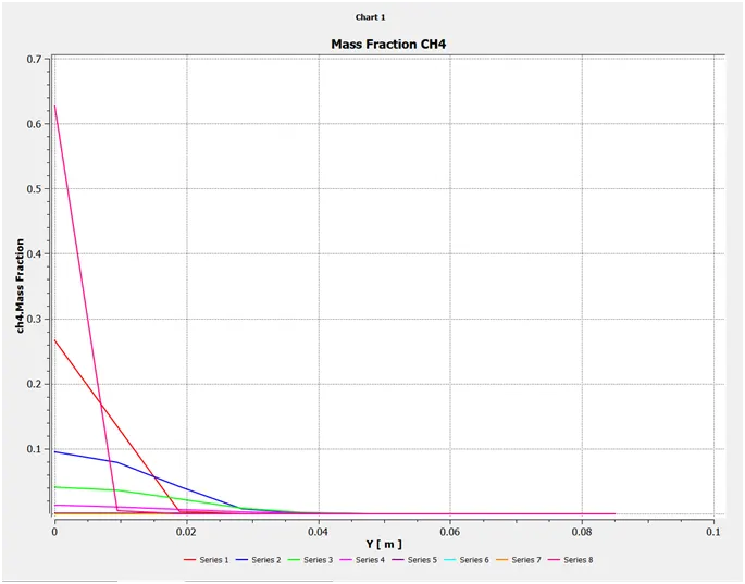
N2 Mass Fraction
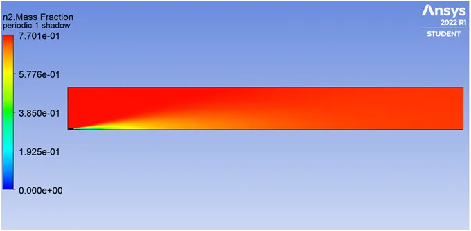
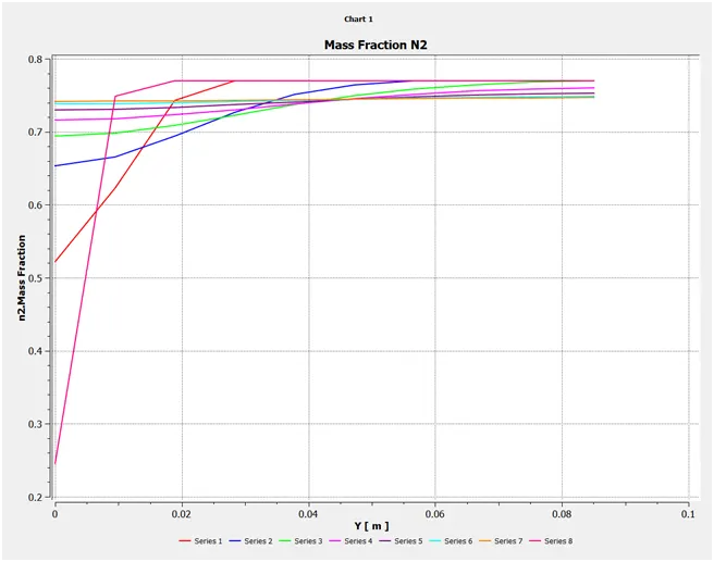
O2 Mass Fraction
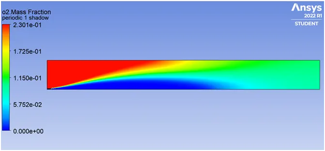
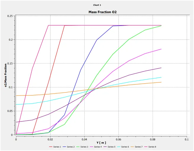
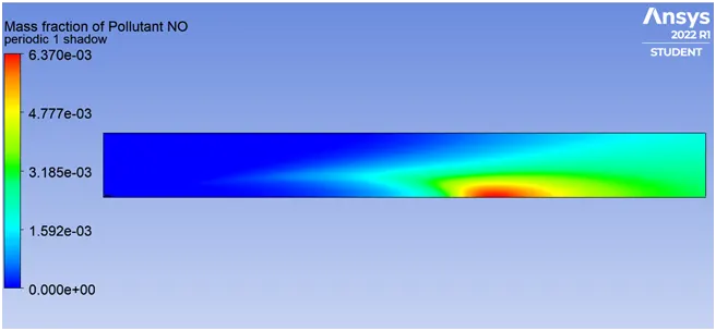
The contour of NOx Mass Fraction:
NO
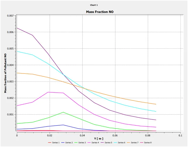
N2O
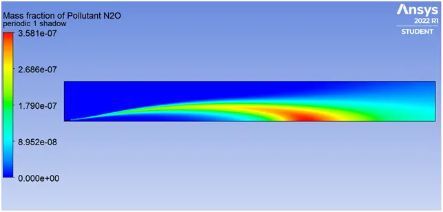
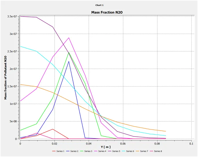
Contours of SOOT Mass Fraction
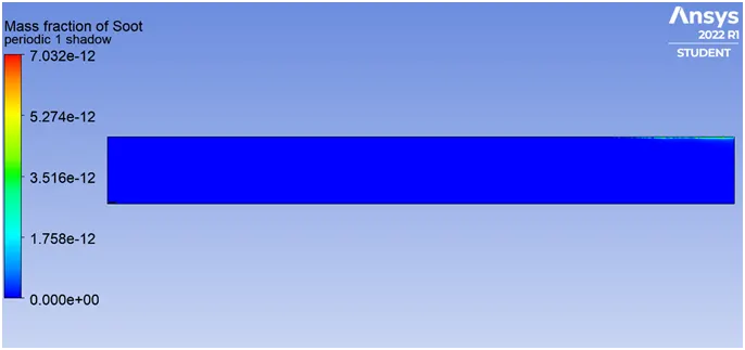
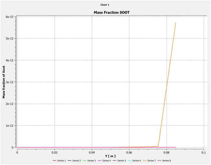
CASE 2
90% CH4 AND 10% H2O
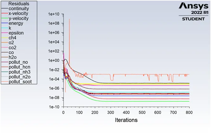
Residuals
Temperature Contour
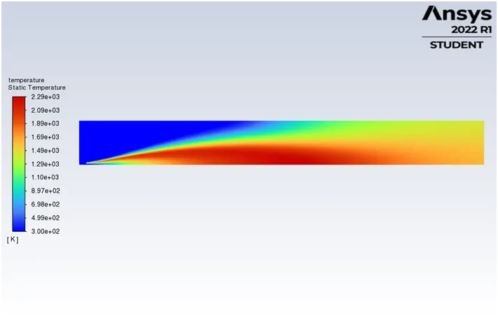
CO2 Mass Fraction
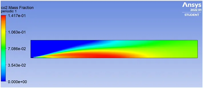
H2O Mass Fraction
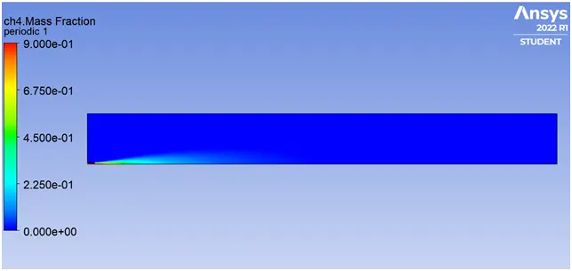
CH4 Mass Fraction
N2 Mass Fraction
O2 Mass Fraction
The contour of NOx Mass Fraction:
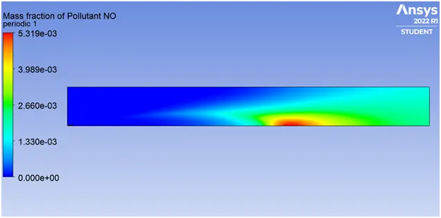
NO
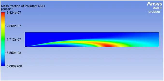
N2O
Contours of SOOT Mass Fraction
CASE 3
80% CH4 AND 20% H2O
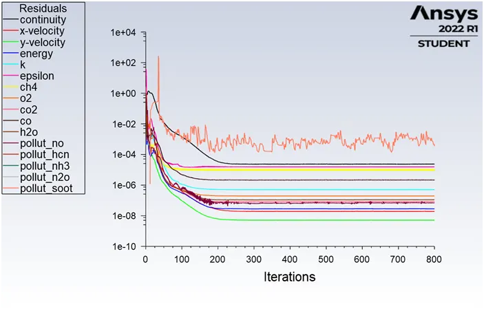
Residuals
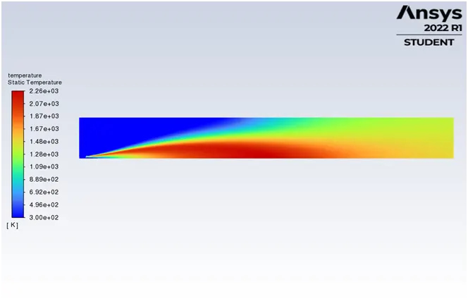
Temperature Contour
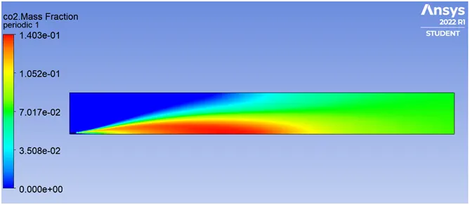
CO2 Mass Fraction
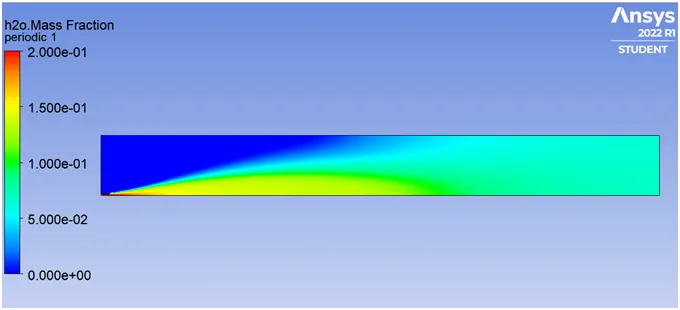
H2O Mass Fraction
CH4 Mass Fraction
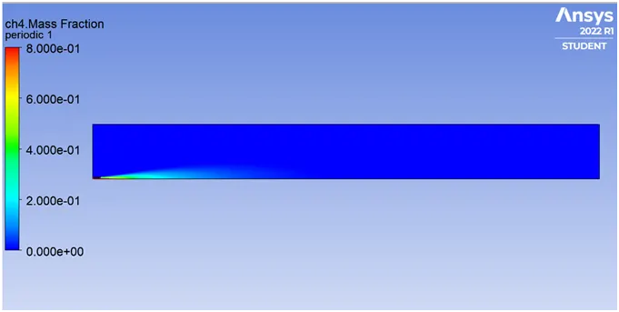
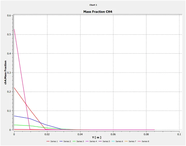
N2 Mass Fraction
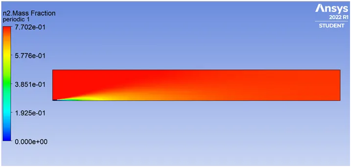
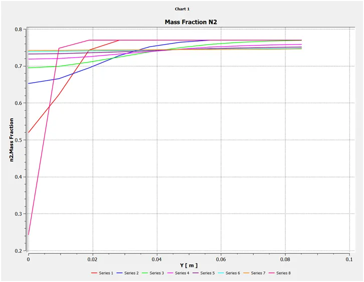
O2 Mass Fraction
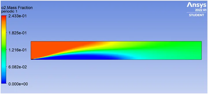
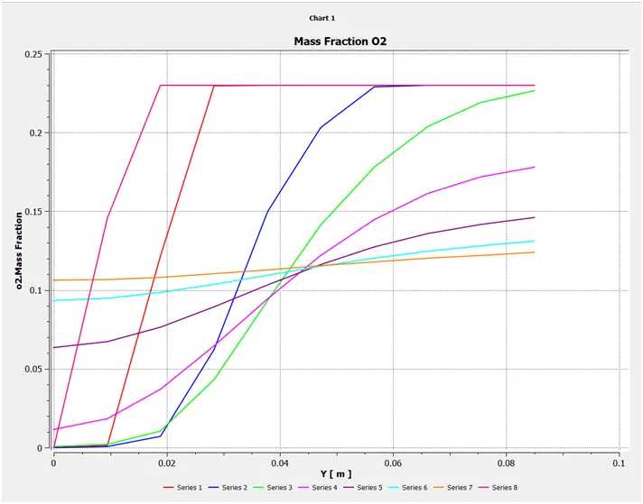
The contour of NOx Mass Fraction:
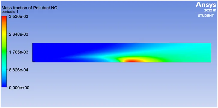
NO
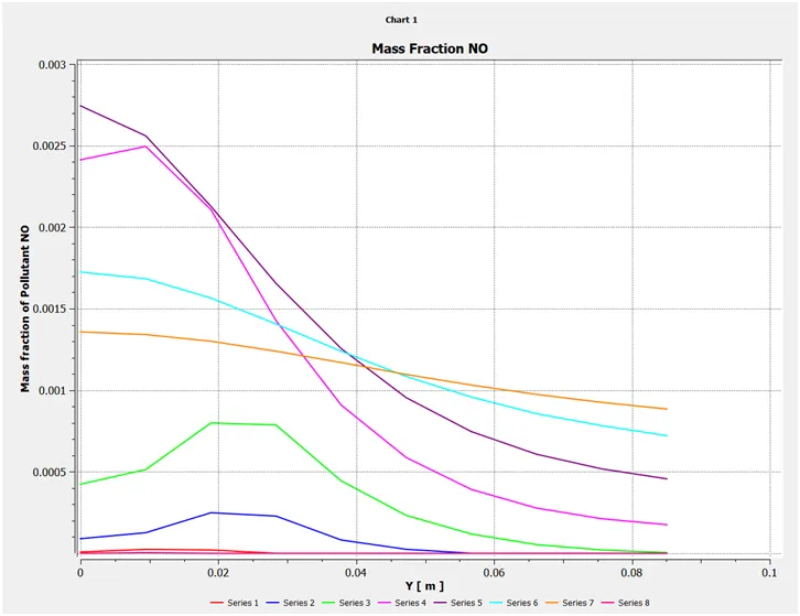
N2O
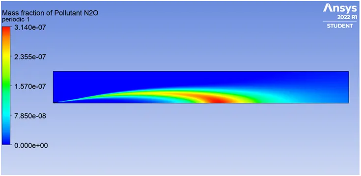
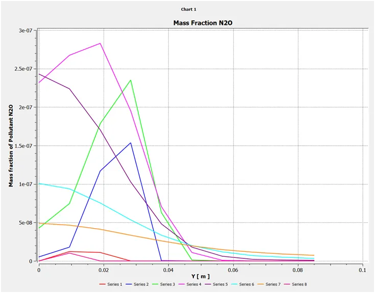
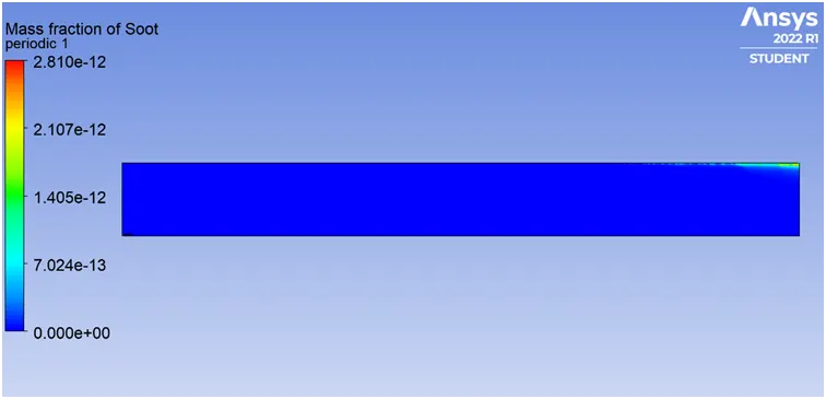
Contours of SOOT Mass Fraction
CASE 4
70% CH4 AND 30% H2O
Residuals
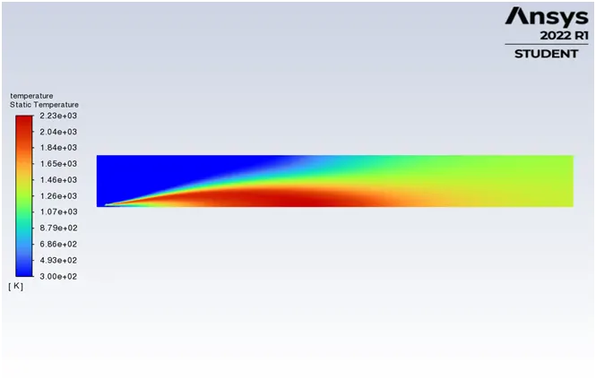
Temperature Contour
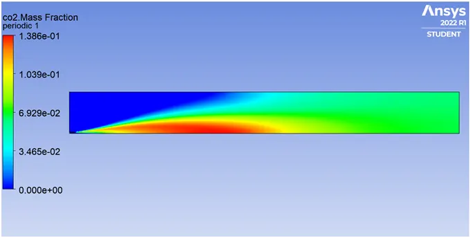
CO2 Mass Fraction
H2O Mass Fraction
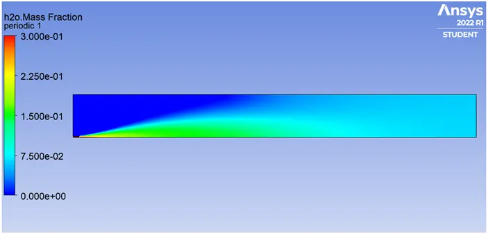
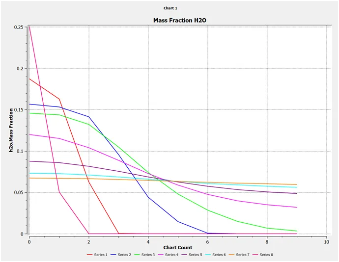
CH4 Mass Fraction
N2 Mass Fraction

O2 Mass Fraction
Contour of NOx Mass Fraction:
NO
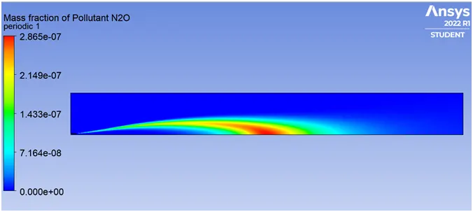
N2O
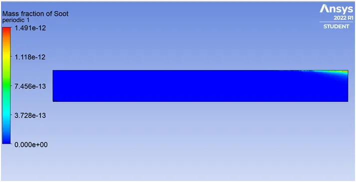
Contours of SOOT Mass Fraction
OBSERVATIONS
- As there is no ignition source for combustion, the rate of reactions is controlled by turbulence mixing in the Eddy Dissipation model. So, with a large eddy mixing time scale, combustion starts when turbulence comes into the picture.
- It can be noticed from the beginning, that CH4 is burning from high at 1 to near 0. However, in reality, some unburnt carbon particles always remain.
- Due to this incomplete combustion of hydrocarbons, the generation of SOOT or Fly Ash happens.
- NOx emissions can also be noticed, which is due to a reaction that takes place between air nitrogen and oxygen. The maximum quantity of N2 in the contours results from the high amount, i.e. 78% of nitrogen, in the air.
Comparison of Mass Fraction of NOx and Soot
|
CASE |
TEMPERATURE |
MASS FRACTION OF N2O |
MASS FRACTION OF NO |
MASS FRACTION OF SOOT |
|
Zero Water Addition |
2.31e + 03 |
3.76e - 07 |
7.59e - 03 |
1.08e - 11 |
|
Case 1 |
2.30e + 03 |
3.58e - 07 |
6.37e – 03 |
7.03e - 12 |
|
Case 2 |
2.29e + 03 |
3.42e - 07 |
5.32e – 03 |
4.13e – 12 |
|
Case 3 |
2.26e + 03 |
3.14e - 07 |
3.53e - 03 |
2.86e – 12 |
|
Case 4 |
2.23e + 03 |
2.87e - 07 |
2.17e - 03 |
1.49e - 12 |
- It can be observed that very small decrease in temperature from Case1 to Case2, as water is added in fuel in each case from 5% to 30%.
- The small decrease in NOx emission can be documented as there is an increase in water quantity also with a significant amount of decrease in SOOT formation from 5% to 30%.
CONCLUSION
- It can conclude that the addition of water to the fuel helps in decreasing NOx and SOOT formation.
- Water addition leads to an increase in OH radicals that might have a significant impact on SOOT Oxidation and reduce the SOOT formed in the Gas Phase.
- Added water dilutes calories generated by combustion. That decreases combustion temperature. If temperature reduces significantly, NOx cannot form in great concentration.
- However, with a small decrease in temperature, reducing temperature means avoiding stoichiometric ratio. If this ratio is low, it generates a lower concentration of thermal NOx.
- Therefore, with these or various types of technologies, the NOx and SOOT formation can be reduced, which helps to meet regulatory requirements by the government.
The simulation provides a complete temperature distribution along the geometry. Contours of various species can be studied. By adding water, the pollutant soot and NOx formation at the outlet is reduced.
REFERENCES
- https://en.wikipedia.org/wiki/Combustion
- https://en.wikipedia.org/wiki/Combustion_models_for_CFD#:~:text=Combustion%20models%20for%20CFD%20refers,in%20the%20form%20of%20heat.
- https://www.sciencedirect.com/science/article/pii/S1876610217337724
- https://link.springer.com/article/10.1007/s00773-015-0303-8