Week 10 - Simulating Combustion of Natural Gas.
INTRODUCTION :
Combustion is defined as a chemical reaction in which a hydrocarbons fuel reacts with a oxidant to form products, accompained by the release of energy in the form of heat.
Combustion manifests itself as a wide domain during the design, analysis, and performance characteristics stage by being amn integral part of various engineering application like internal combustion engines, furnances, and power station combustors.
Natural gas is an extremely important source of energy for reducing pollution and maintaining a clean and healthy environment. In addition to being a domestically abundant and secure source of energy, the use of natural gas also offers a number of environment benifits over other sources of energy, particularly other fossil fuels.
Types of Combustion simulation -
Based on mixing
Non premixed combustion
In non-premixed combustion, fuel and oxidizer enter the reaction zone in distinct streams. Examples of non-premized combustion include pulverized coal furnaces, diesel internal-combustion engines and pool fires.
Pre-mixed combustion
Premixed systems, in which reactants are mixed at the modecular level before burning.
Partially pre-mixed
Partially pre-mixed combustion model that is based on the non-premixed combustion model described in nonpremixed combustion and the premixed combustion model described in premixed combustion.
Based on Phase
- Fluid - When combustion is taking place in fluid phase (Volumetric reactions)
- Wall - When combustion is taking place on wall (surface reactions)
- Praticles - when reaction is taking place Lagrangian Phase
Simulation Procedure :
Step 1 : Geometry Preparation
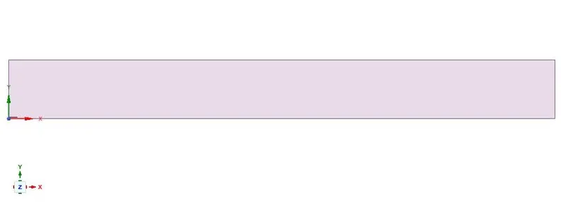
First of all, upload the 3D geometry and convert this into 2d geometry
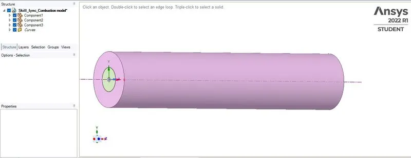
the 2d geometry is created in Spaceclaim which is given below :
Step 2 : Meshing
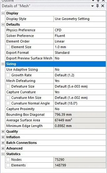
Here i am going to provide the Element size of 1mm for meshing
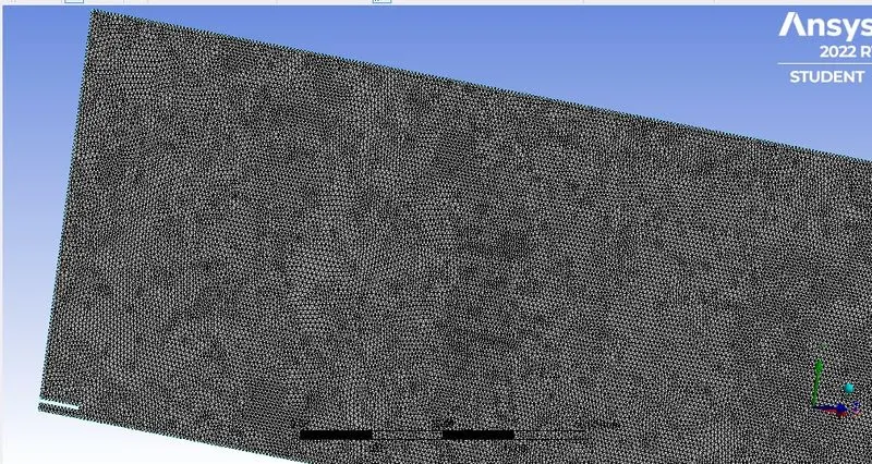
Now i am going to provide the name slection of the body
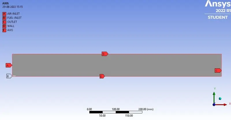
In this, the meshing is generated with enabling Proximity after giving Name selection
Step 3: Set-Up
General :
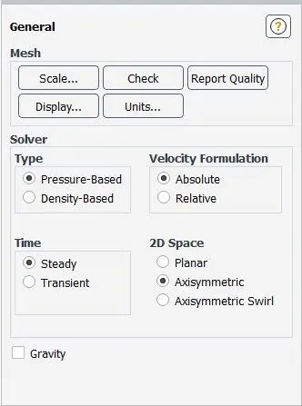
and this set-up lets's hit on the buttion of Energy Equation.
Viscous-model :
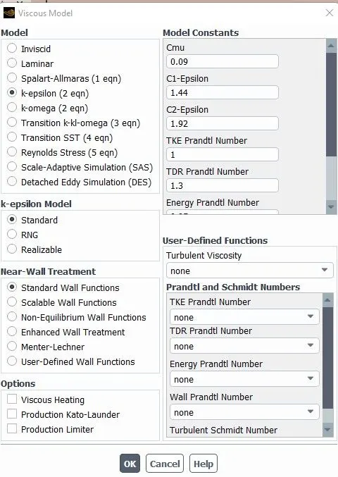
Species Model :
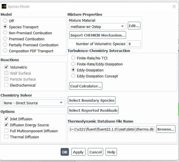
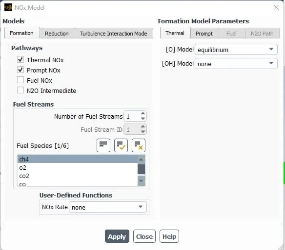
NOx Model :
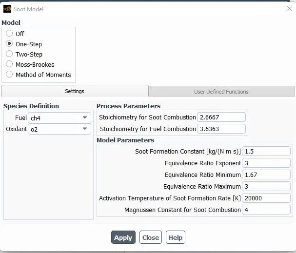
Soot Model :
and now i am going to provide the boundaries conditions as given below :
Air inlet velocity : 0.5m/s
Air Inlet temperature : 300k
Fuel Inlet temperature : 300k
Fuel inlet velocity : 80m/s
the above parameters are remain same for all the cases but
species Mass fraction at Air inlet and fuel inlet is going to be vary
let's give for the first case
Air inlet 02 : 0.23
Fuel inlet Ch4 : 1
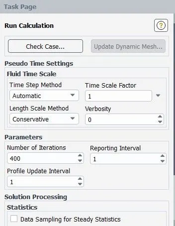
and after all this hit on the initialiize button and Run the simulation for 400 iteration
Step 4 : Results
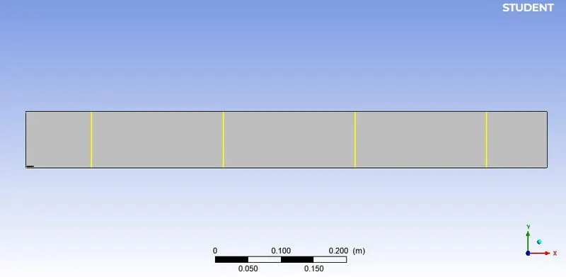
LINE PROBES :
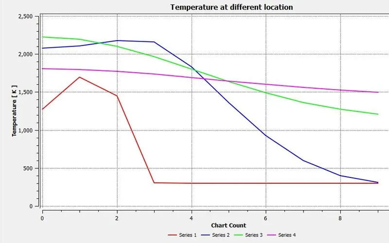
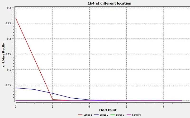
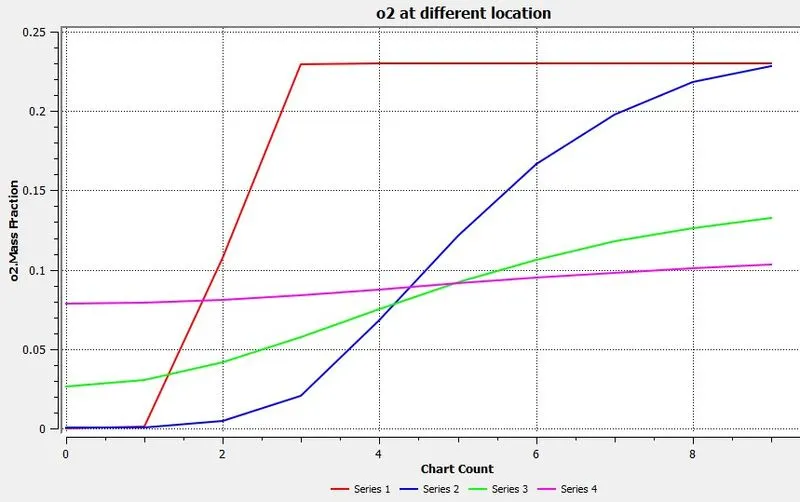
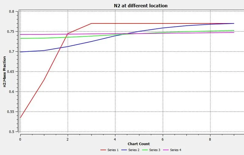
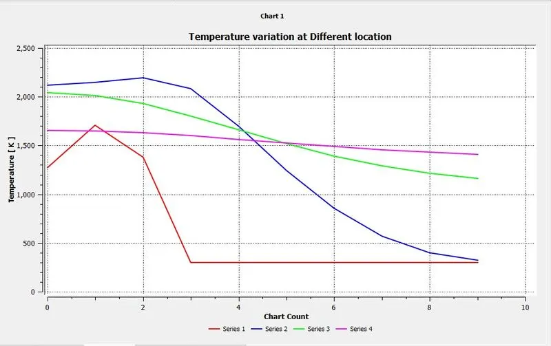
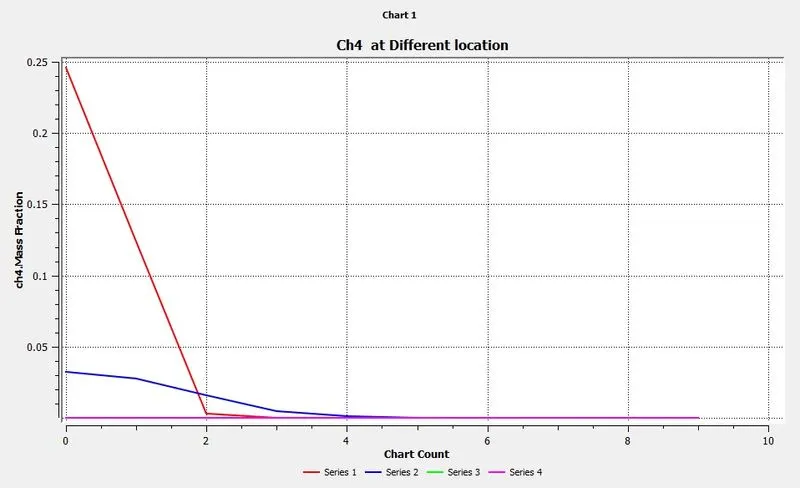
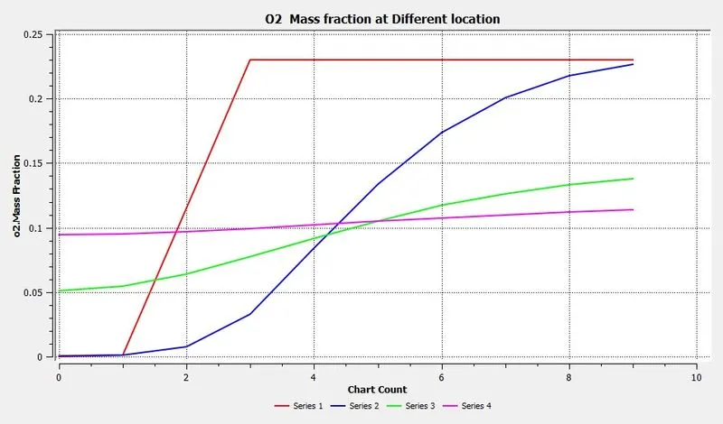
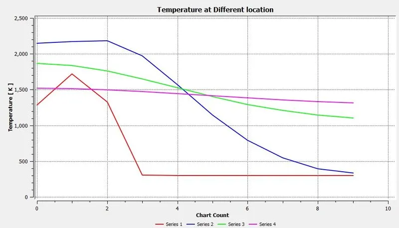
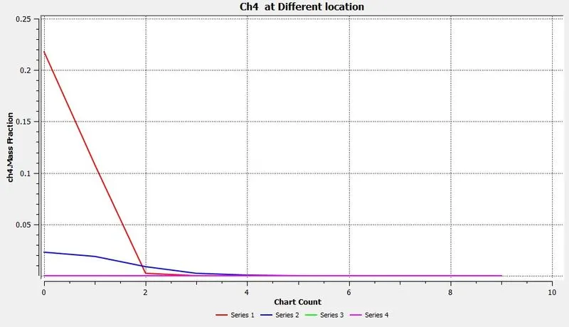
Lines probes located at X = 0.1m, X = 0.3m , X = 0.5m , X = 0.7m
CASE 1 : In this part , H2O is not mixed with inlet fuel . Total Mass fraction of ch4 is only used as inlet fuel
AIR INLET --->Species --> Species Mole Fraction --> O2 = 0.21, Ch4= 0, CO = 0, CO2 = 0, H2O = 0
FUEL INLET --->Species --> Species Mole Fraction --> O2 = 0.21, Ch4= 1, CO = 0, CO2 = 0, H2O = 0
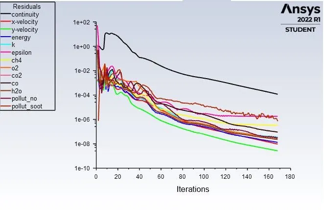
Residuals:
Values of Nox and SOOT :
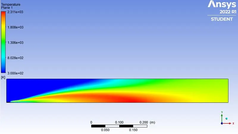
Temperature Contour :
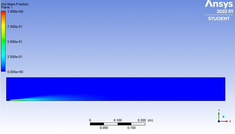
Fuel & Oxidant Contour :
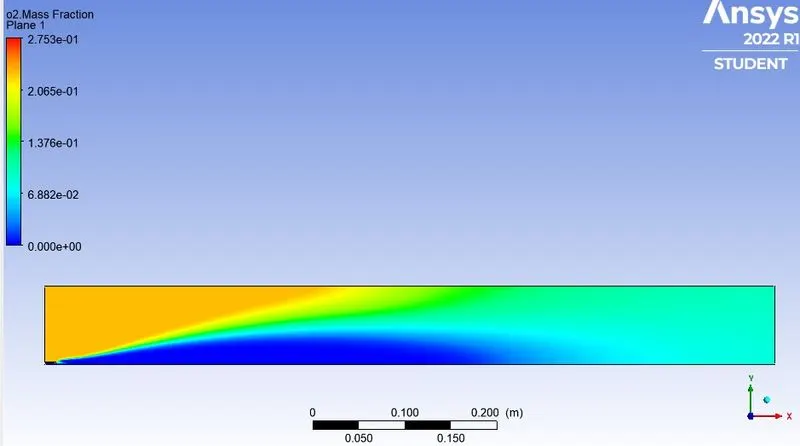
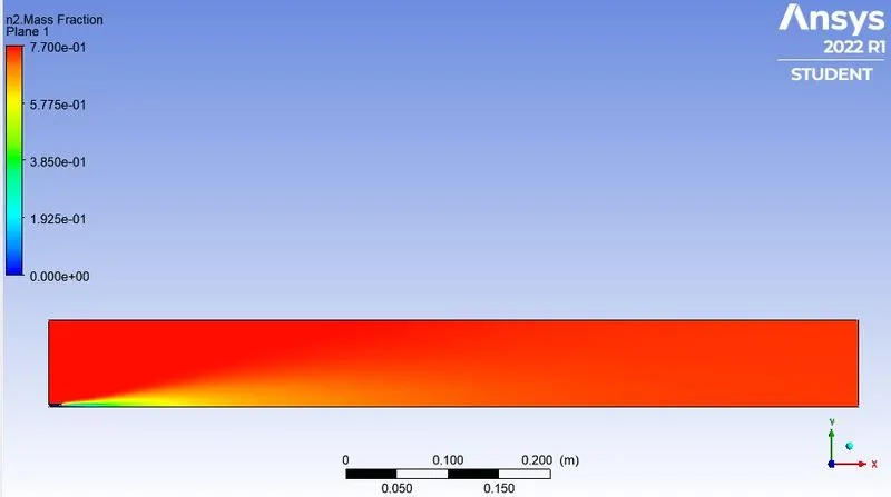
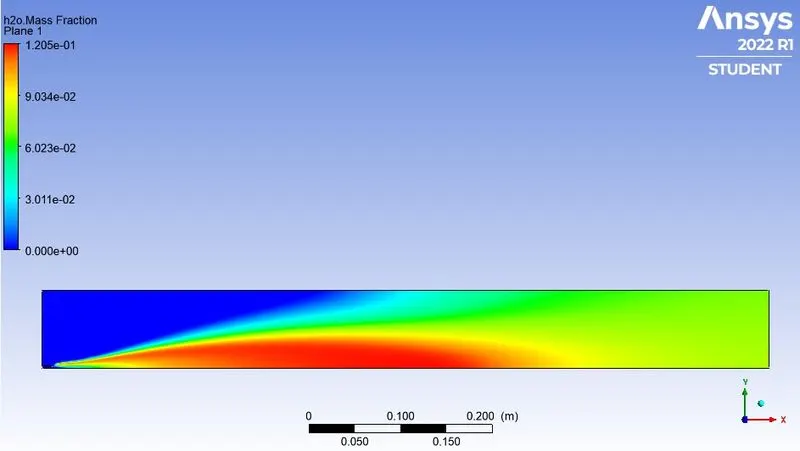
Inert & Non-Pollutant Combustion Products Contour :
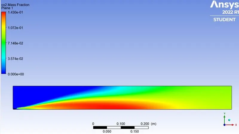
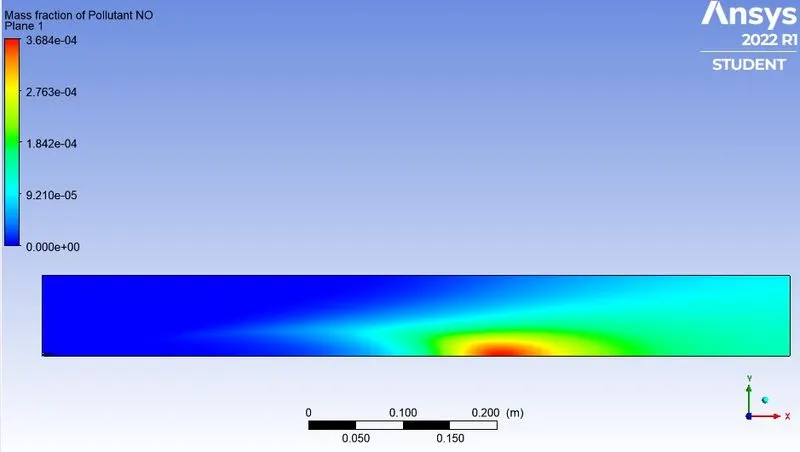
Pollutant Combustion Products Contour :
Variation Plots :
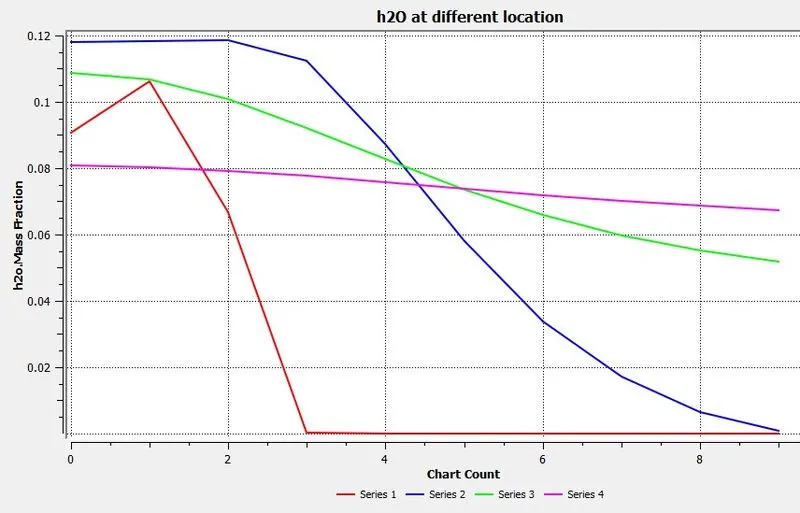
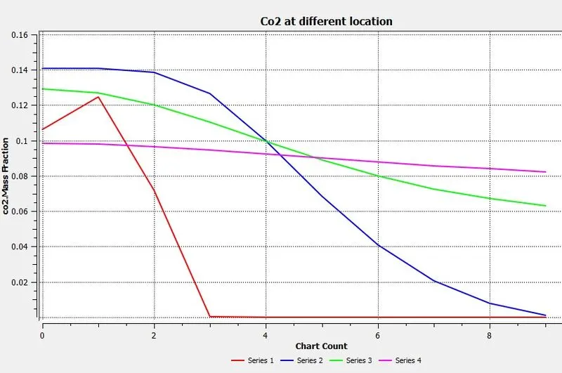
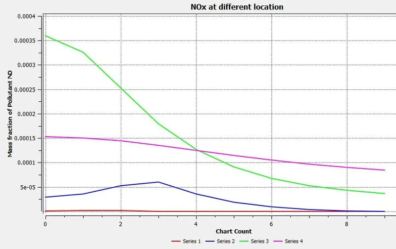
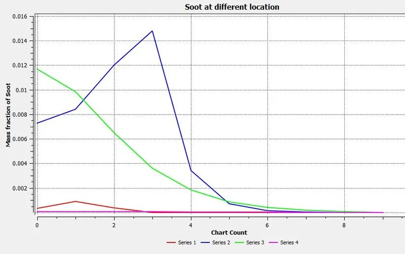
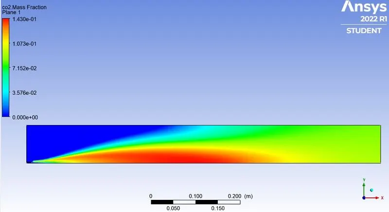
CASE 2 (ADDING WATER CONTENT IN FUEL BY MOLE 5%) :
AIR INLET --->Species --> Species Mole Fraction --> O2 = 0.21, Ch4= 0, CO = 0, CO2 = 0, H2O = 0
FUEL INLET --->Species --> Species Mole Fraction --> O2 = 0.21, Ch4= 0.95, CO = 0, CO2 = 0, H2O = 0.05
Hybrid Initialization
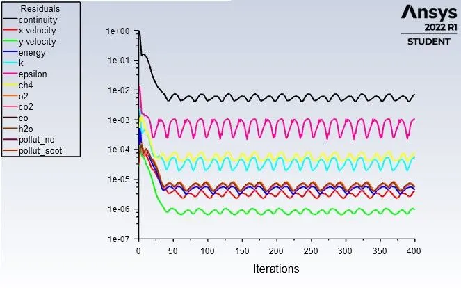
Residuals :
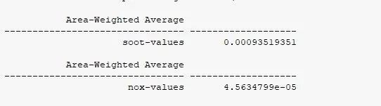
Values of Nox and SOOT :
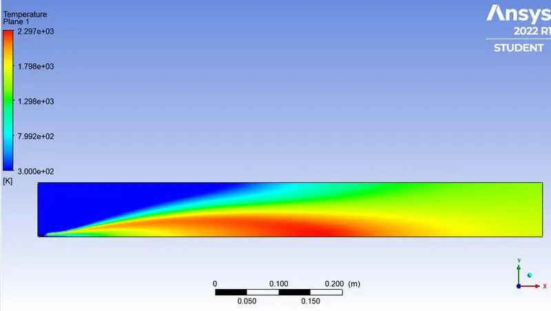
Temperature Contour :
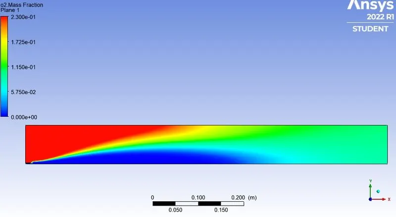
Fuel & Oxidant Contour :
Inert & Non-Pollutant Combustion Products Contour :
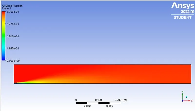
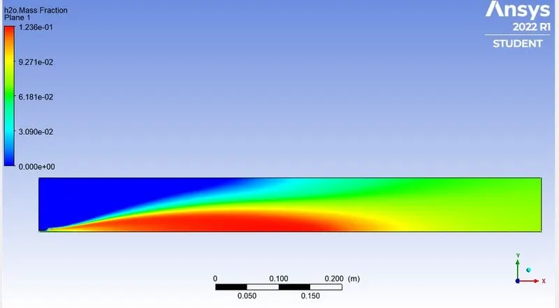
Pollutant Combustion Products Contour :
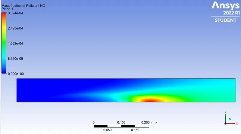
Variation Plots :
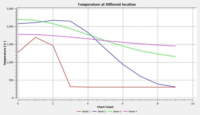
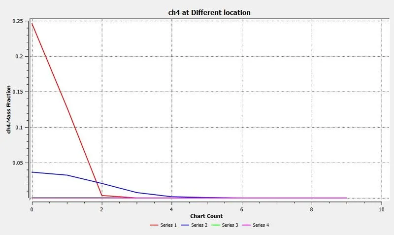
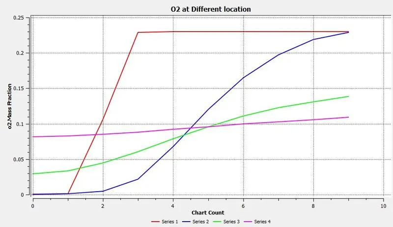
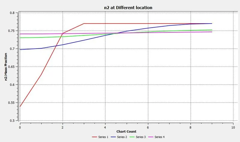
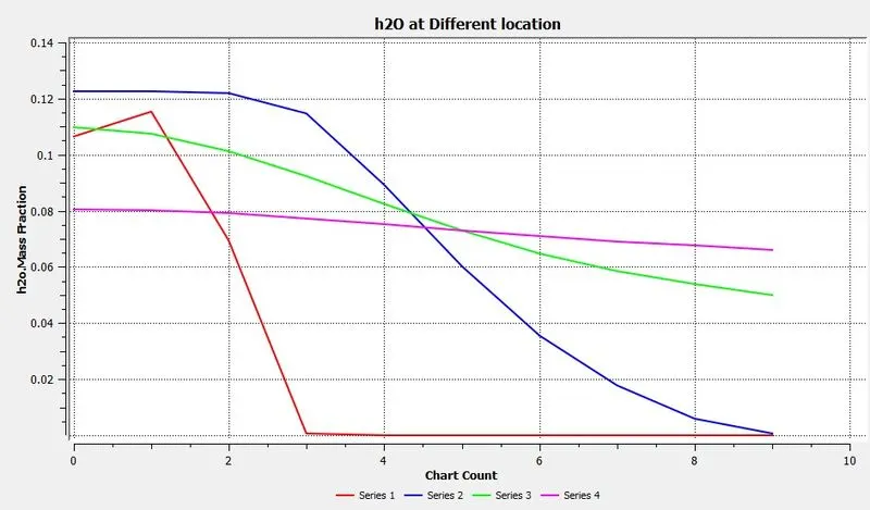
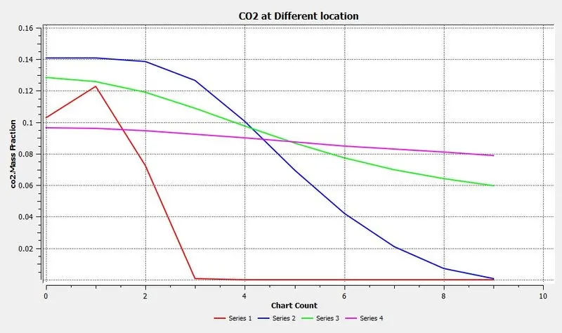
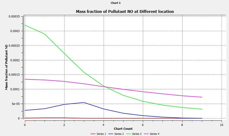
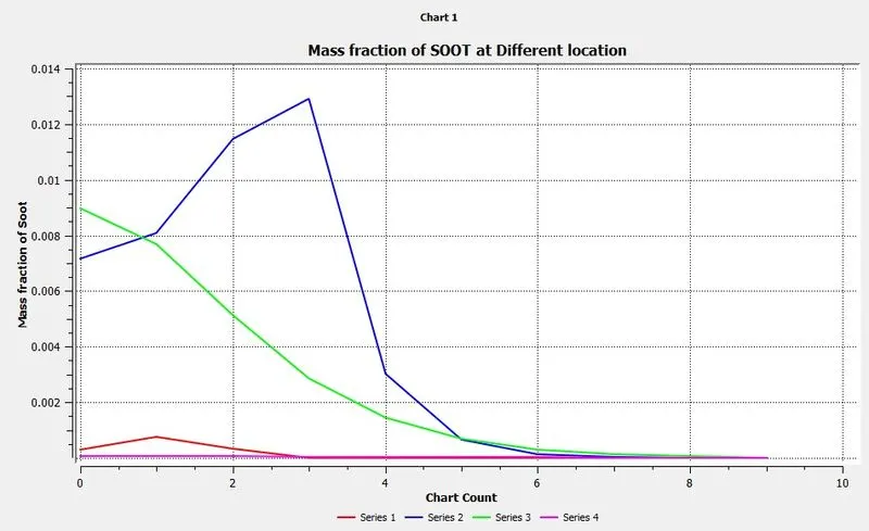
CASE 3 (ADDING WATER CONTENT IN FUEL BY MOLE 10%) :
AIR INLET --->Species --> Species Mole Fraction --> O2 = 0.21, Ch4= 0, CO = 0, CO2 = 0, H2O = 0
FUEL INLET --->Species --> Species Mole Fraction --> O2 = 0.21, Ch4= 0.9, CO = 0, CO2 = 0, H2O = 0.1
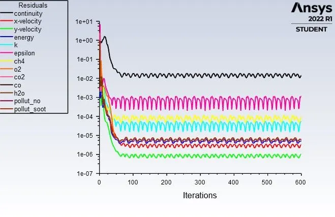
Residuals :
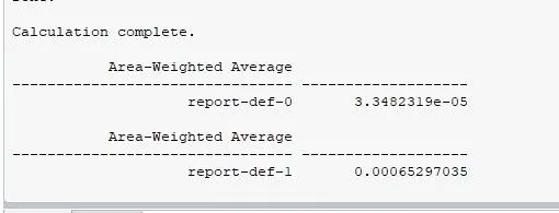
Values of Nox and SOOT :
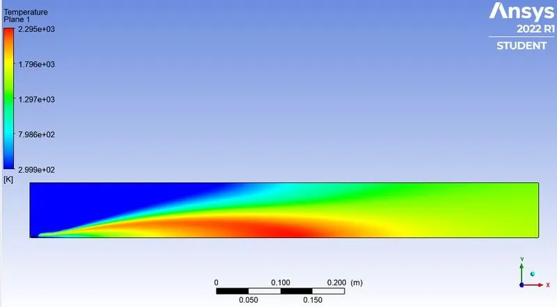
Temperature Contour :
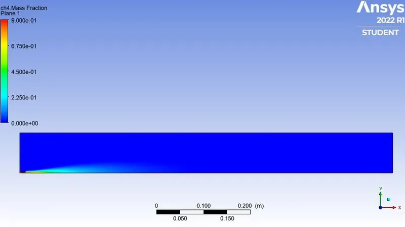
Fuel & Oxidant Contour :
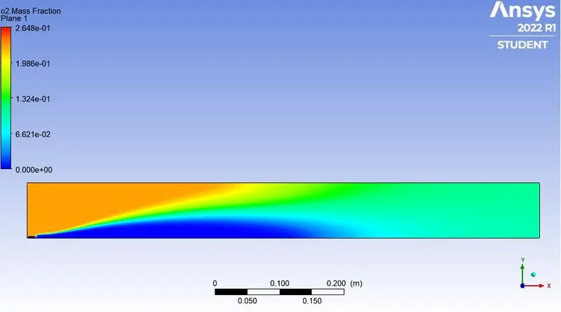
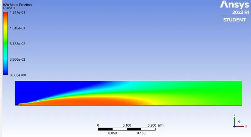
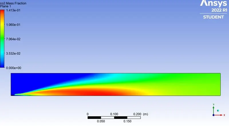
Inert & Non-Pollutant Combustion Products Contour :
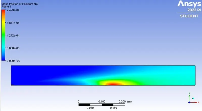
Pollutant Combustion Products Contour :
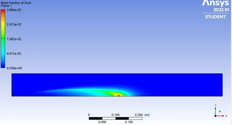
Variation Plots :
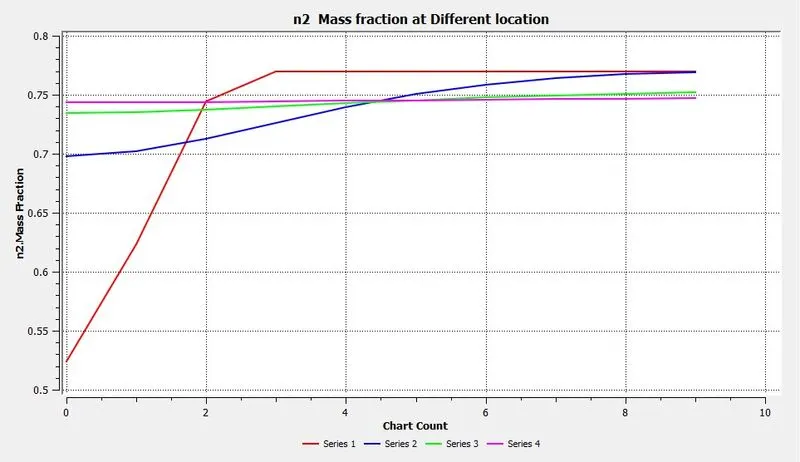
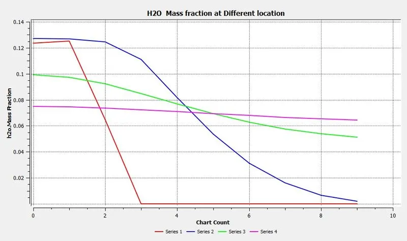
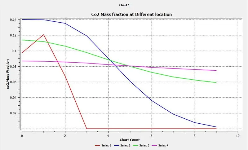
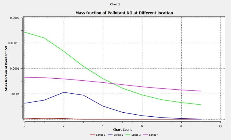
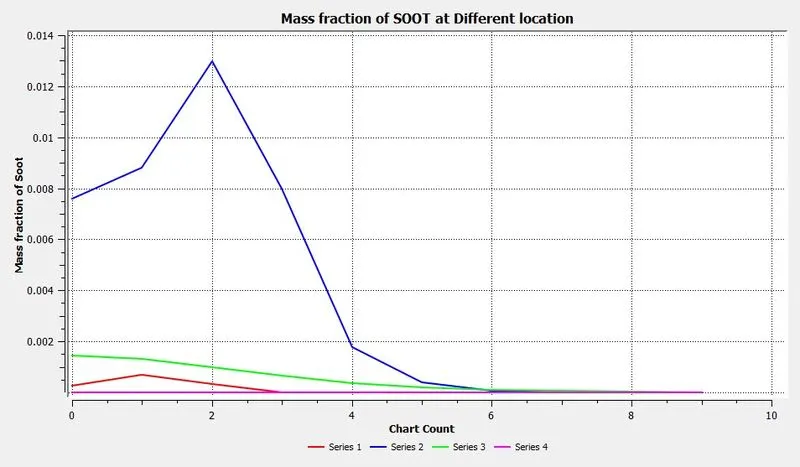
CASE 4 (ADDING WATER CONTENT IN FUEL BY MOLE 20%) :
AIR INLET --->Species --> Species Mole Fraction --> O2 = 0.21, Ch4= 0, CO = 0, CO2 = 0, H2O = 0
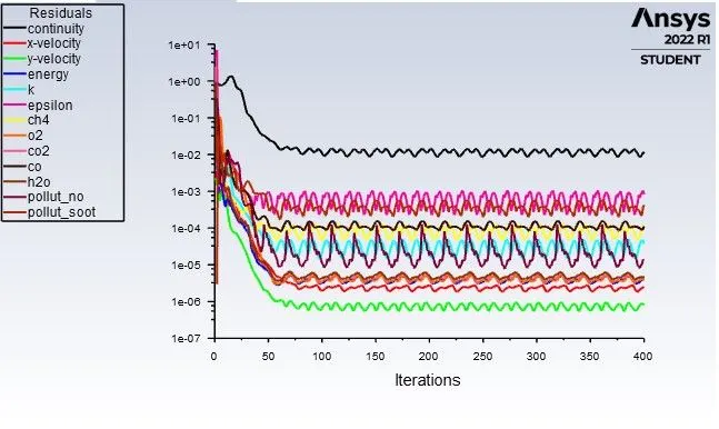
FUEL INLET --->Species --> Species Mole Fraction --> O2 = 0.21, Ch4= 0.8, CO = 0, CO2 = 0, H2O = 0.2
Residuals:
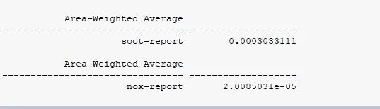
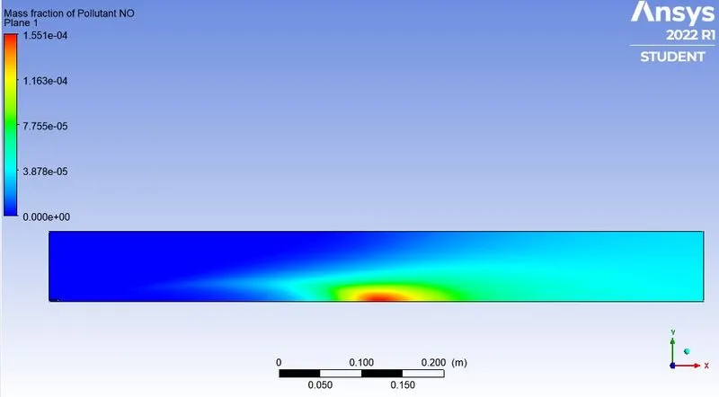
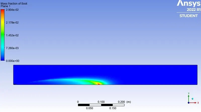
Values of Nox and SOOT :
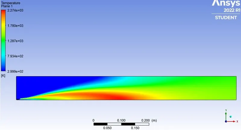
Temperature Contour :
Fuel & Oxidant Contour :
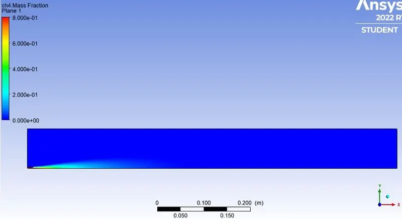
Inert & Non-Pollutant Combustion Products Contour :
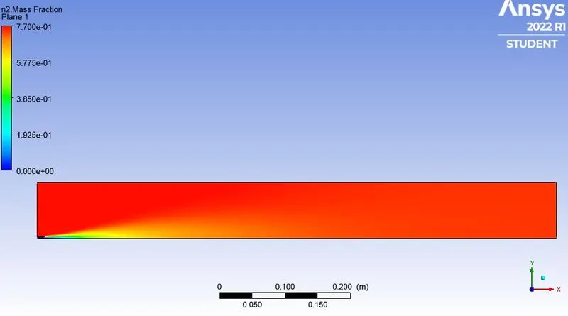
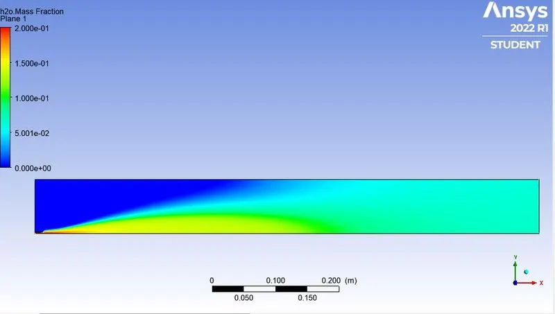
Pollutant Combustion Products Contour :
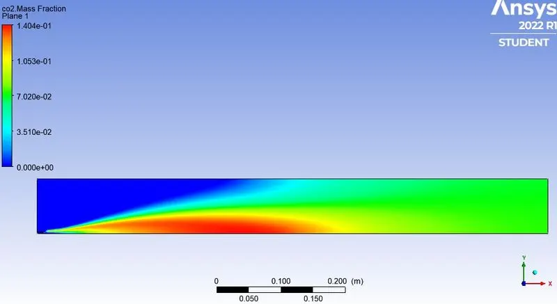
Variation Plots :
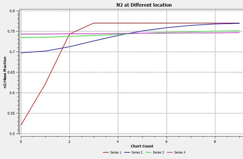
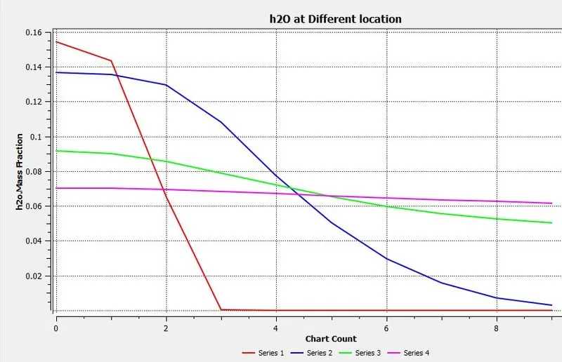
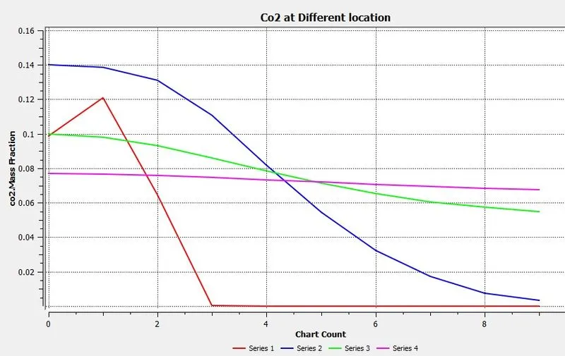
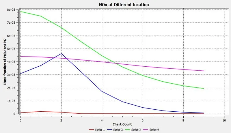
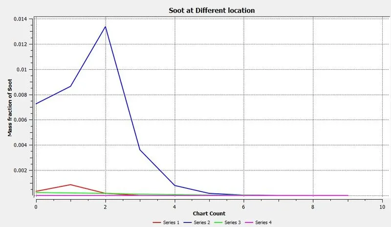
CASE 5 (ADDING WATER CONTENT IN FUEL BY MOLE 30%) :
AIR INLET --->Species --> Species Mole Fraction --> O2 = 0.21, Ch4= 0, CO = 0, CO2 = 0, H2O = 0
FUEL INLET --->Species --> Species Mole Fraction --> O2 = 0.21, Ch4= 0.7, CO = 0, CO2 = 0, H2O = 0.3
Residuals:
Values of Nox and SOOT :
Temperature Contour :
Fuel & Oxidant Contour :
Inert & Non-Pollutant Combustion Products Contour :
Pollutant Combustion Products Contour :
Variation Plots :
The purpose of supplying Water :
Minimizing temperature peaks during the combustion process in cyclinders, hence Nox concentration in exhaust gas, can be done by means of supplying water into the cylinders(so-called wet technologies). The emulsion supplied into the cylinder causes the increases of self-ignition delay which affets the flammable mixture becomes more homogeneous in the whole volume of the combustion chamber. The increased self-ignition delay extends the time necessary to spread the injected fuel which results in fewer zones in which not enough oxygen. That decreases the intensity of Soot and CO formation.
water supplied into the combustion chamber, apart from lowering the combustion temperature also decreases the concentration of atomic oxygen by reaction :
H`H_2 O rarr OH + H`
`H_2 O + O rightarrow OH + OH`
`H_2 + O rightarrow H + Oh`
`H + O_2 rightarrow OH + O`
which influences the reaction speed
`O + N_2 rightarrow NO + N`
`O + N_2 + OH rightarrow N_2O + OH`
OH formed this way is more difficult to interact with atomic N, which as a consequences , significantly lower the amount of NO.
Variation of Mass fraction of NOx and soot as water is added to fuel by 5% to 30% by mole
|
Ch4 Mass Fraction |
H20 Mass Fraction |
NOx Mass Fraction |
Soot Mass Fraction |
| 0.95 | 0.05 | 3.38011e-5 | 0.00057086 |
| 0.90 | 0.10 | 3.34823e-5 | 0.00065297 |
| 0.80 | 0.20 | 2.00850e-5 | 0.00030331 |
| 0.70 | 0.30 | 9.37837e-6 | 0.00013109 |
Conclusion :
It can be clearly seen that the Values of Nox and Soot are going to be decreasing as we adding the water into the combustion process.