Week 10 - Simulating Combustion of Natural Gas.
OBJECTIVE: To simulate combustion of natural gas.
THEORY: Combustion is defined as the process of chemical reaction where hydrocarbon fuels react with an oxidant to form products, accompanied by release of energy in form of heat. Combustion process is an integral part of many engineering applications like combustion in internal combustion engines or combustors of power stations. To simulate combustion, we need to solve complex equations from chemical kinetics and have to know the information about reaction mechanism as well. Then it can be simulated by use of various CFD solvers available.
When process of combustion isn’t fully complete, we observe formation of various pollutant which are harmful for all living beings as well as non-living beings. These pollutants include NOx and soot majorly. By simulation of the process various input parameters such as addition of water in the fuel can help reduce the amount of pollutants produced hence combustion simulations are of huge importance.
PROCEDURE:
GEOMETRY
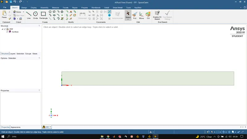
The 3D model of the Combustion chamber/ burner was imported into space claim after which we used the split body tool to cut the model into 1/4th of the original after that we copied the surface of the cross-section we got and pasted into a new design file of space-claim where we removed the solid part of the burner from the 2D geometry and then used the combined tool to combine all other parts into 1 fluid volume after which space-claim was closed.
MESHING
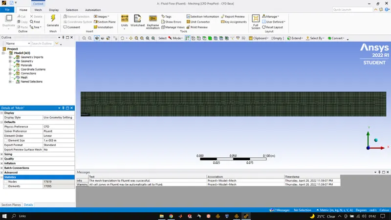
After conversion of burner model from 3D to 2D we open meshing GUI where we name our boundaries appropriately and do the meshing of the 2D profile of the burner element size was set to be 1mm and we enabled cell proximity and the gap was set at 3. Once the meshing was done and we had named our boundaries we close meshing GUI and head to fluent setup.
FLUENT SETUP
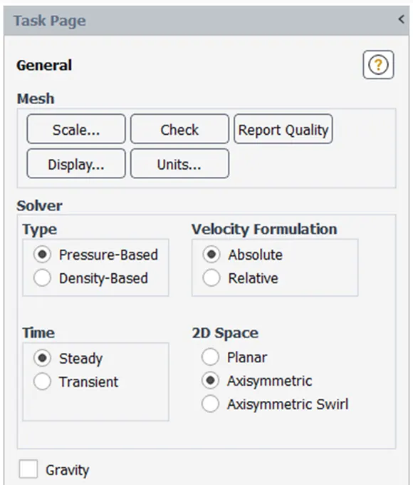
After completing meshing, we open Fluent to setup the simulation process where we head to general and physics and make sure that the simulation is in steady state and the type is selected as axisymmetric.
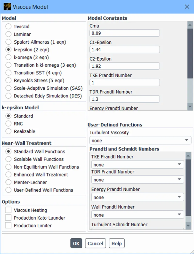
After which we enable energy equation as we will be solving/computing the energy equation to get idea of temperature variation in the simulation. After that the viscous model chosen was k-epsilon standard, standard wall function.
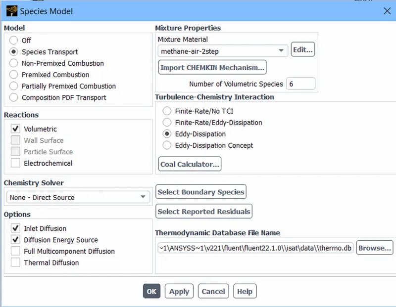
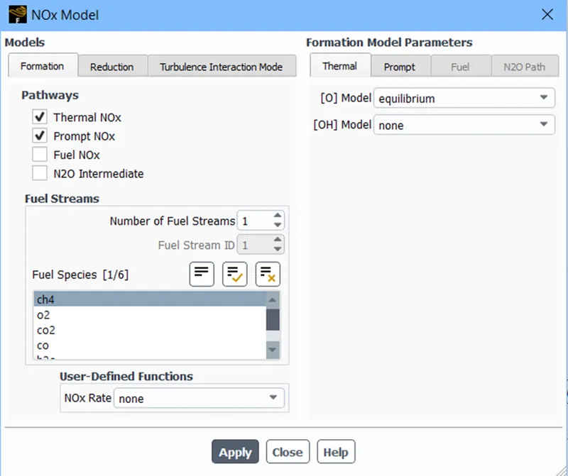
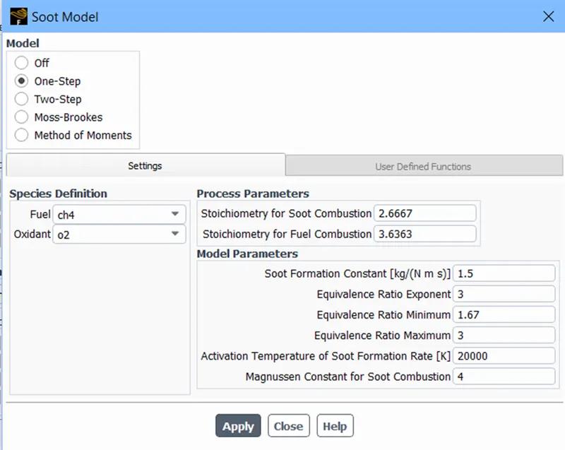
After which we setup species, NOx and soot model where in the Species model species transport equation is enabled and volumetric is selected for reaction. Inlet diffusion was enabled and mixture type selected was methane-air-2step as it allows us to add water into the fuel. Also, the NOx and soot were setup according to simulation conditions.
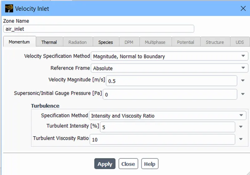
After this we setup our boundary conditions where inlet velocity was set to be 0.5m/s for air and 80m/s for fuel and the species content were selected on mass fraction basis.
Rest other BC were set to be default.
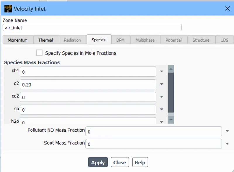
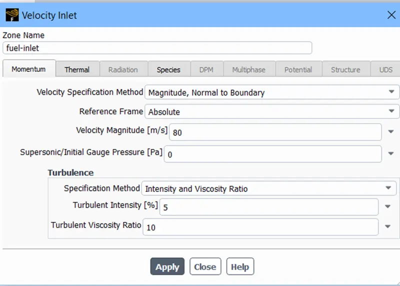
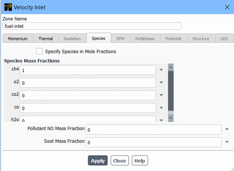
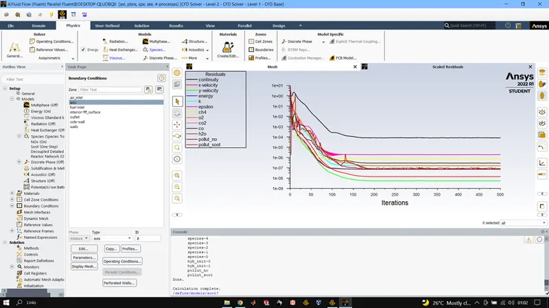
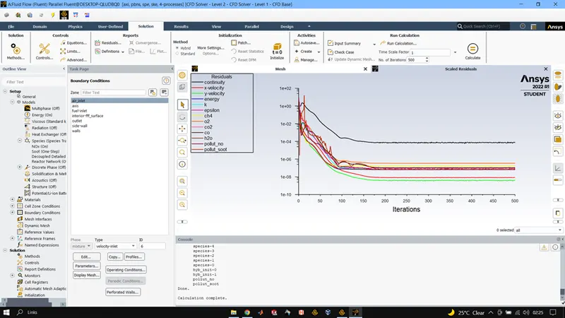
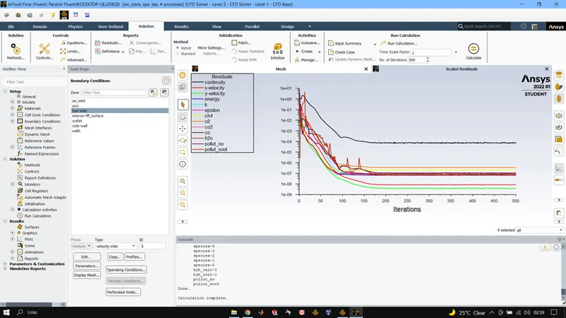
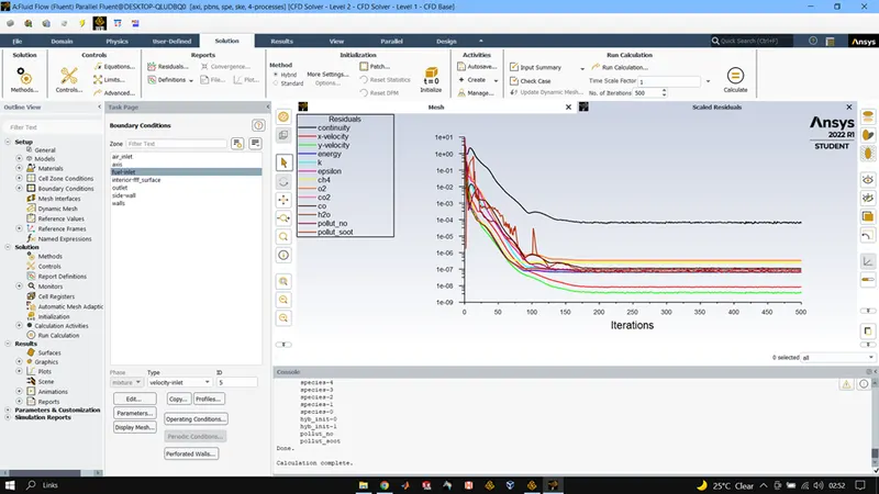
After which simulation was initialized using hybrid solver and then run for 500 iterations and result was calculated.
RESULTS:
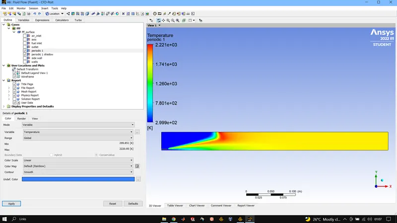
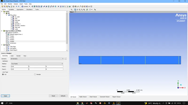
CH4 = 1, 02 = 0.23, H20 = 0
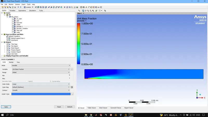
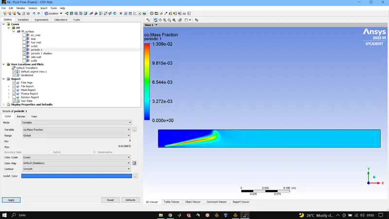
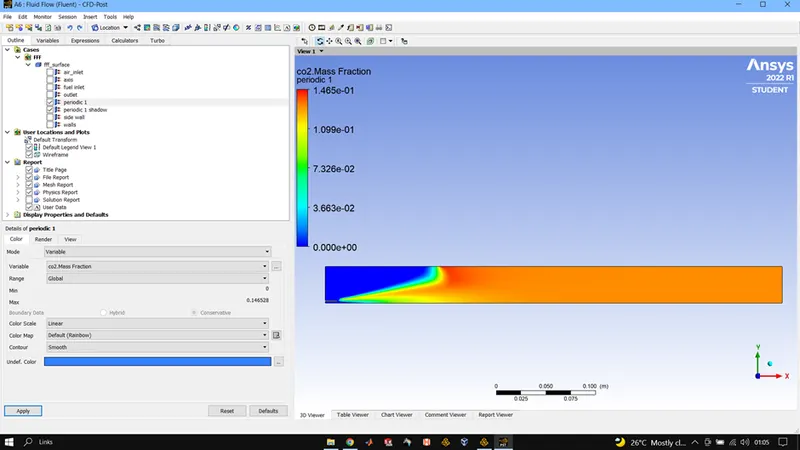
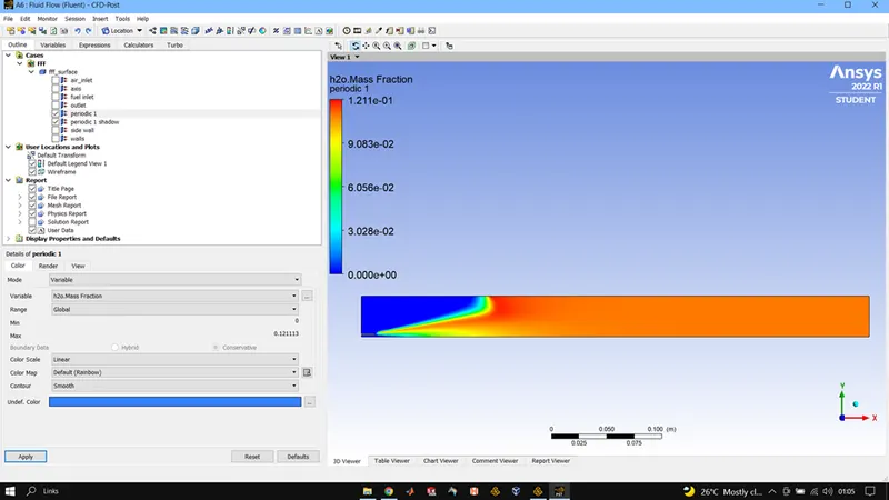
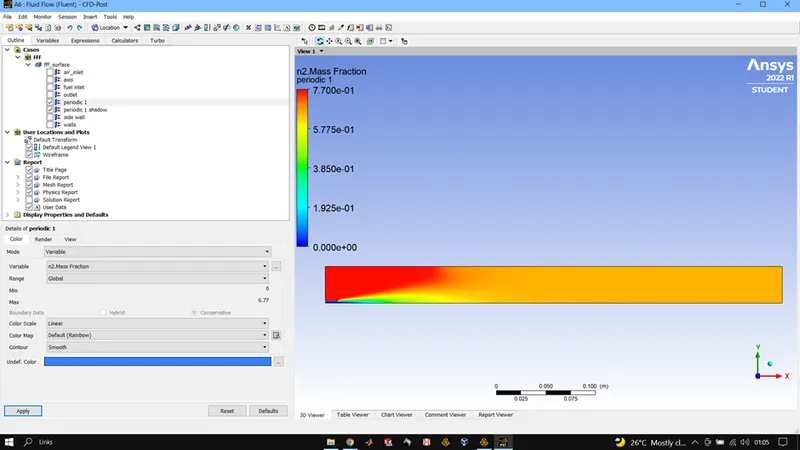
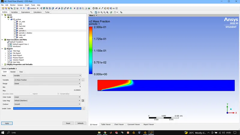
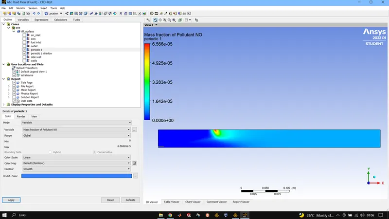
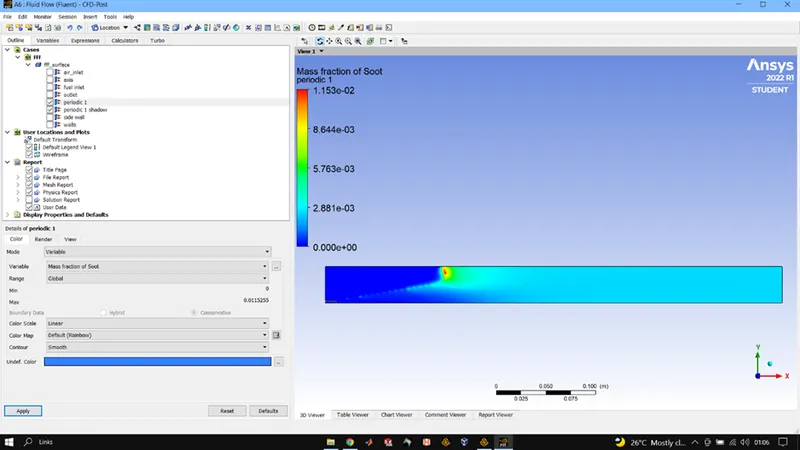
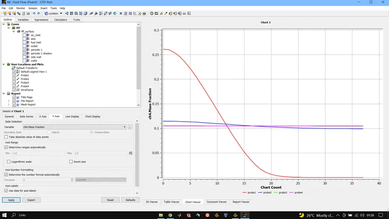
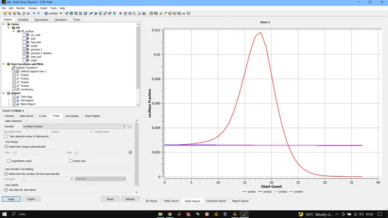
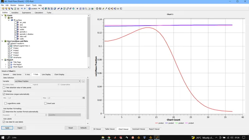
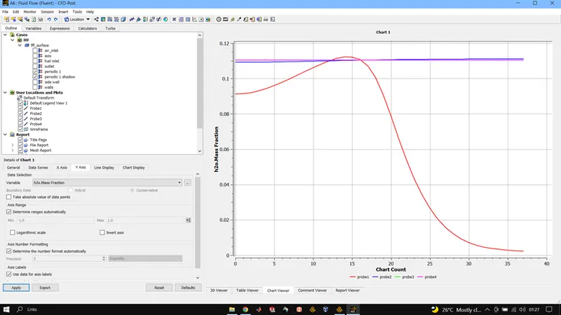
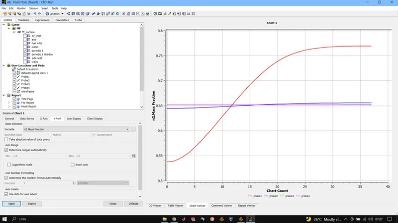
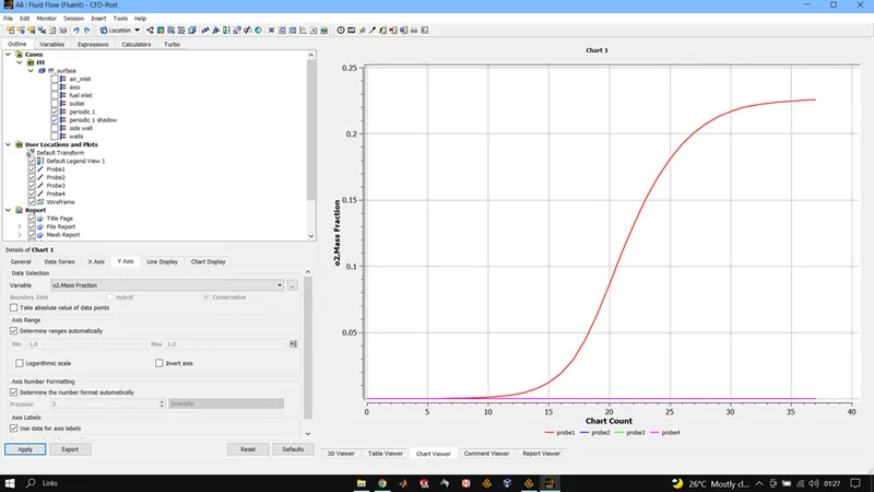
CH4 = 0.95, H2O = 0.05, 02 = 0.21 (MOLE FRACTION WISE)
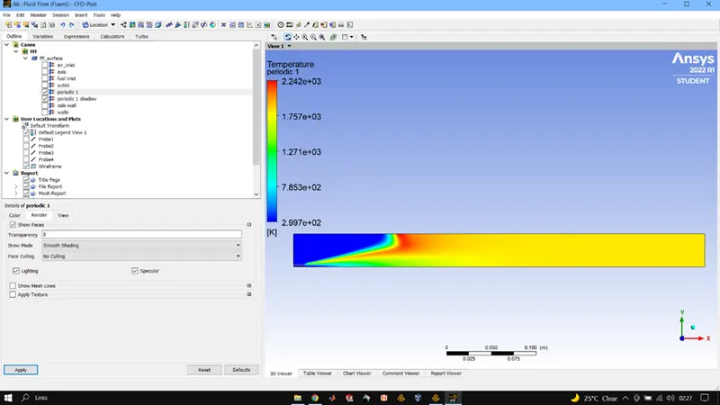
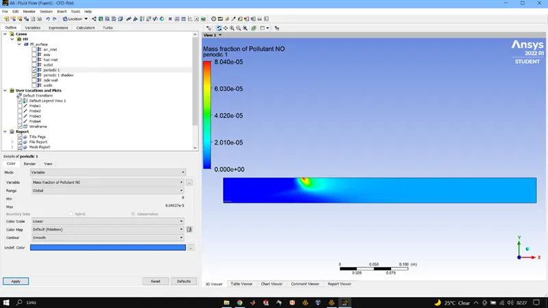
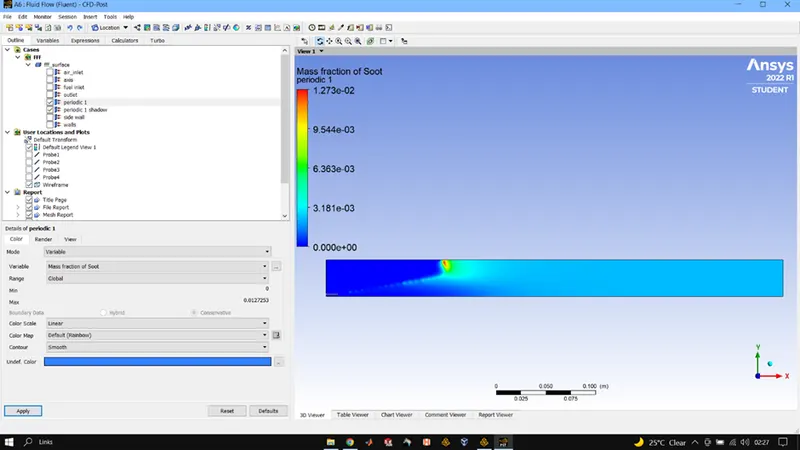
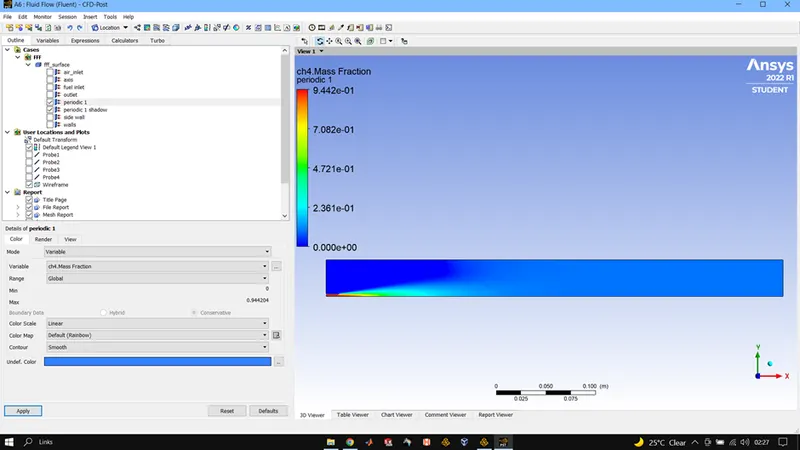
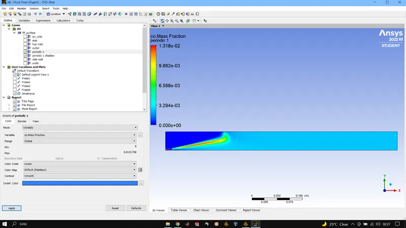
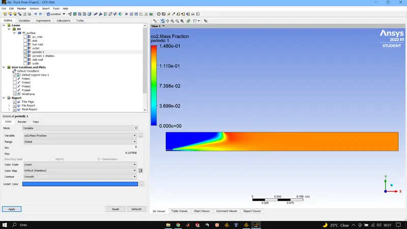
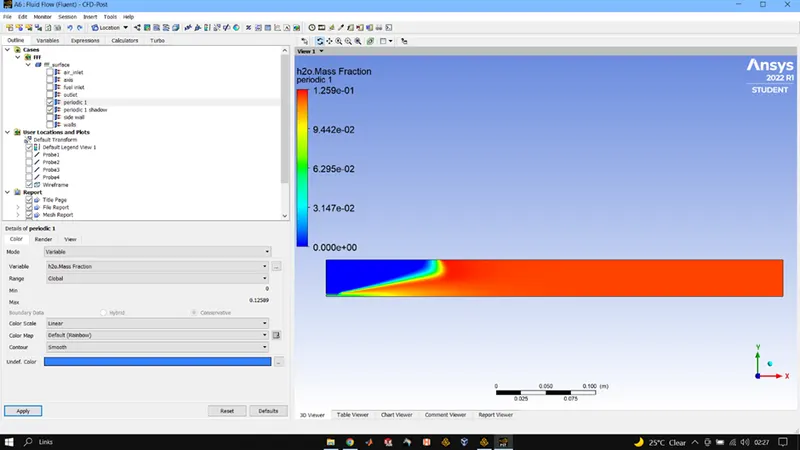
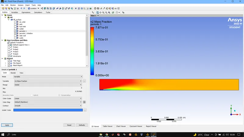
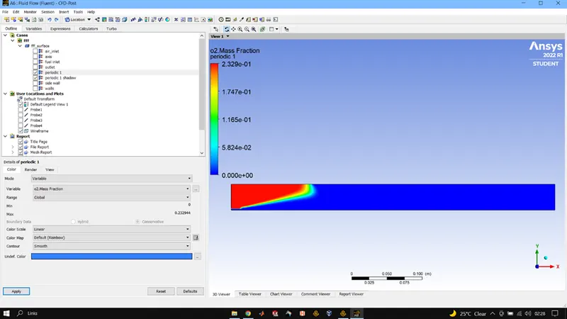
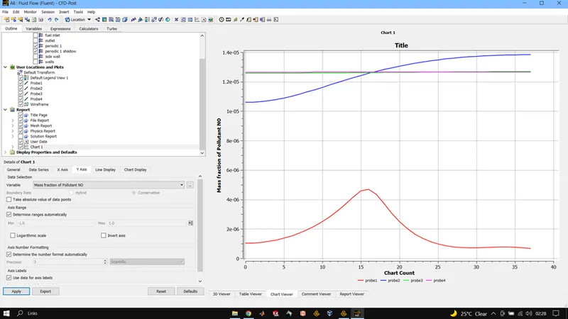
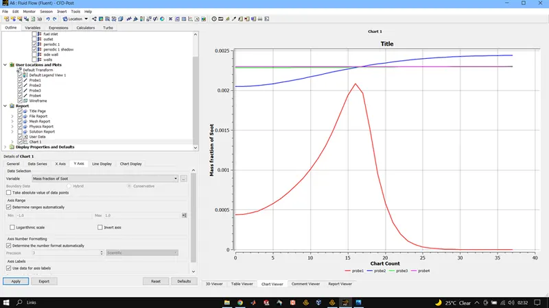
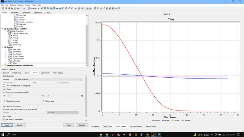
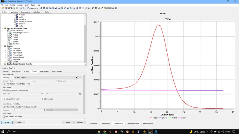
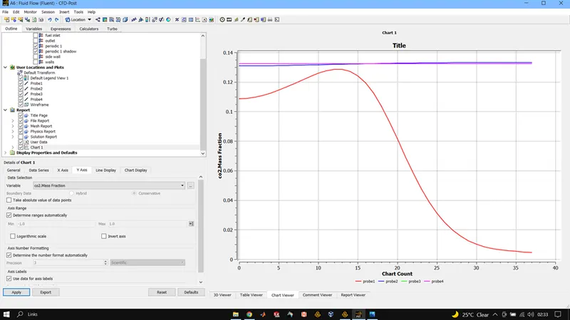
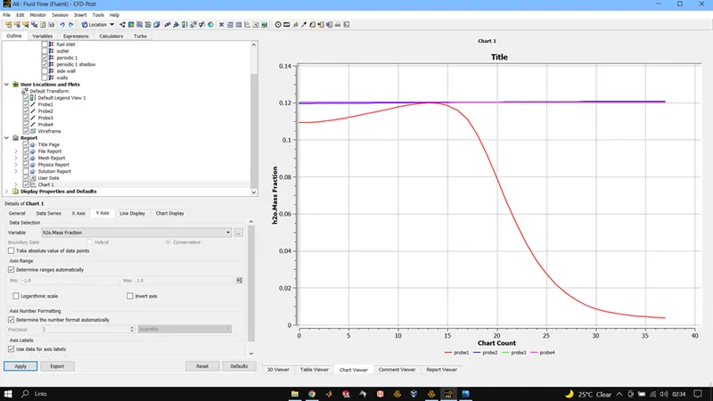
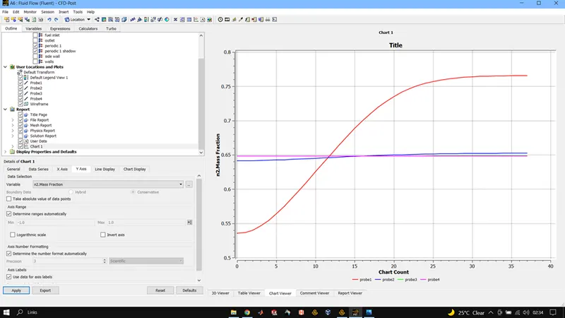
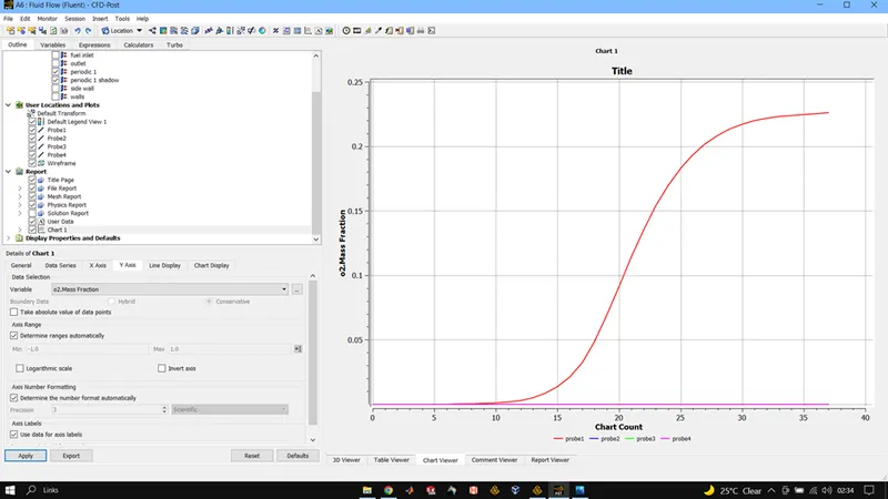
CH4 = 0.85, H2O = 0.15, 02 = 0.21 (MOLE FRACTION WISE)
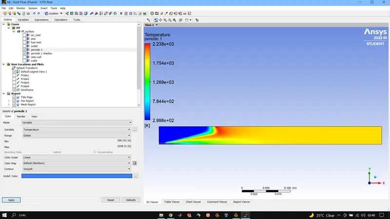
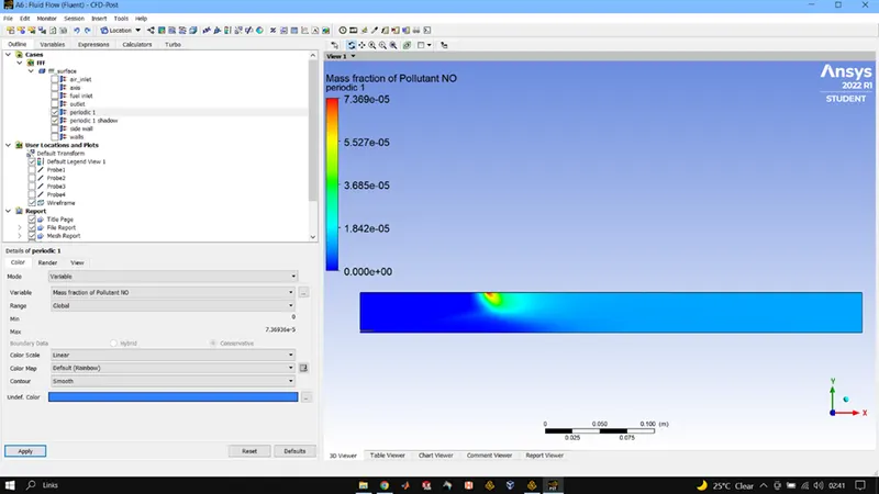
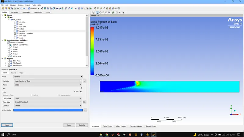
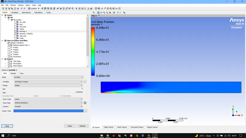
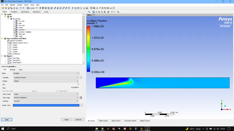
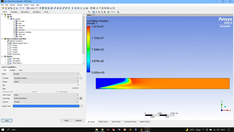
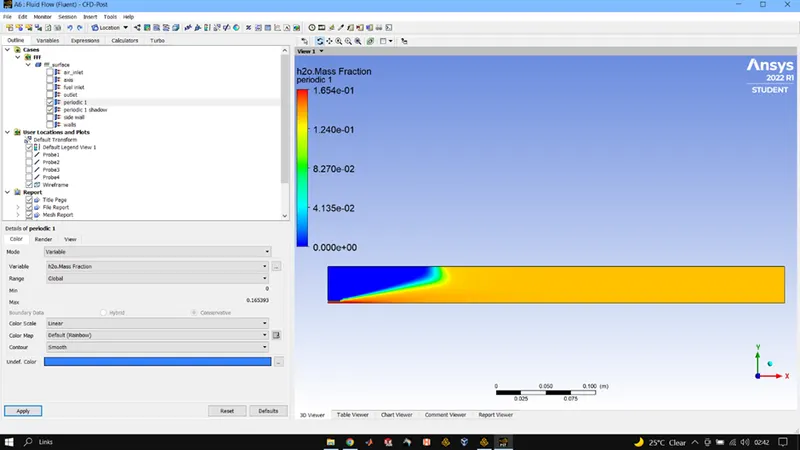
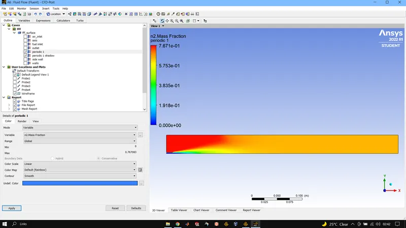
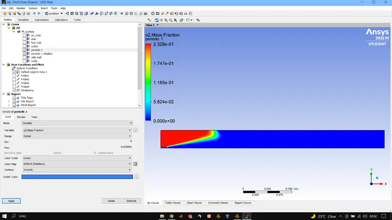
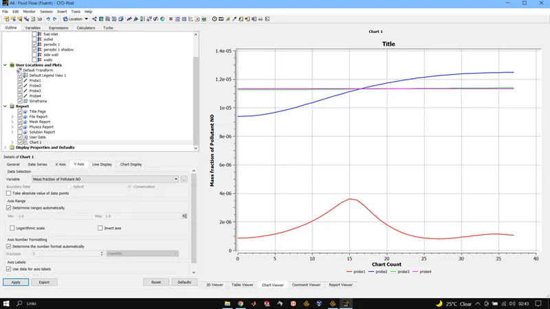
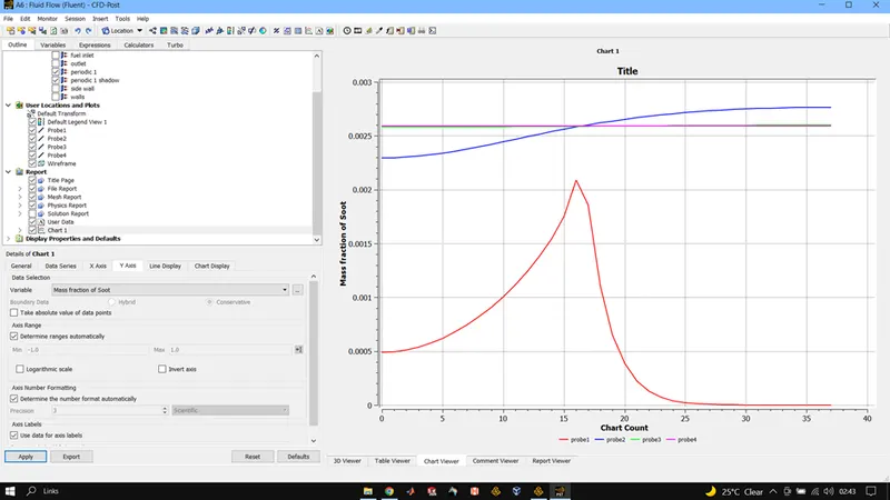
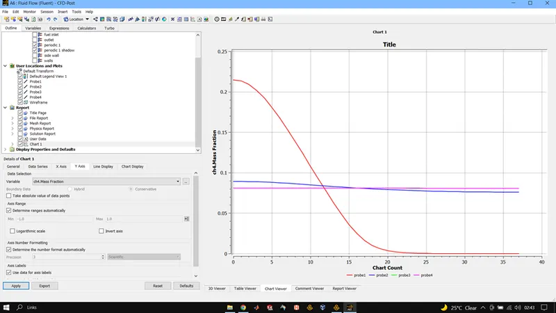
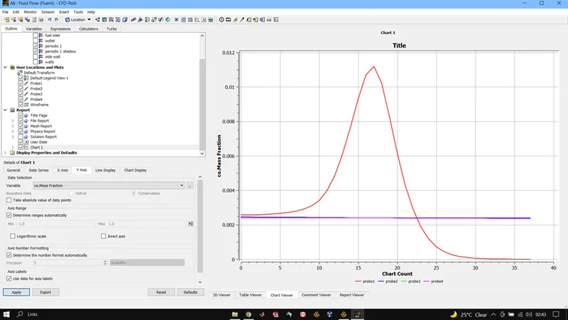
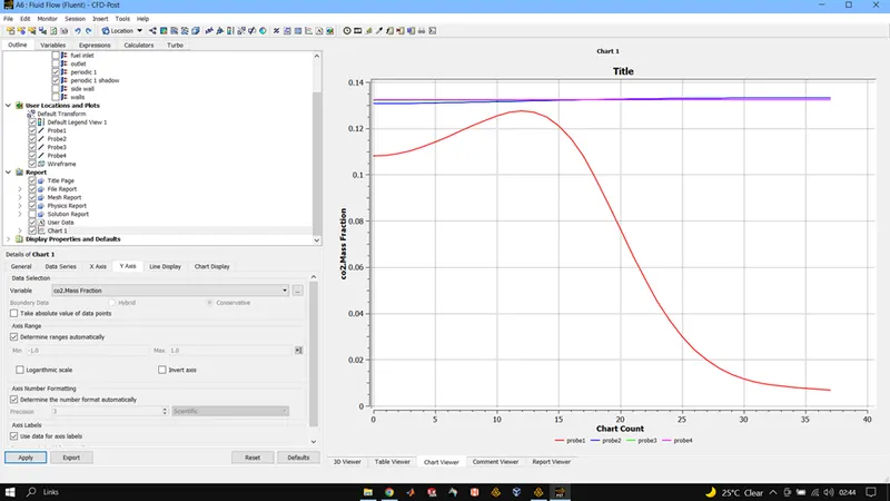
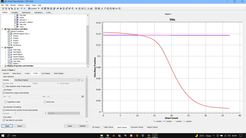
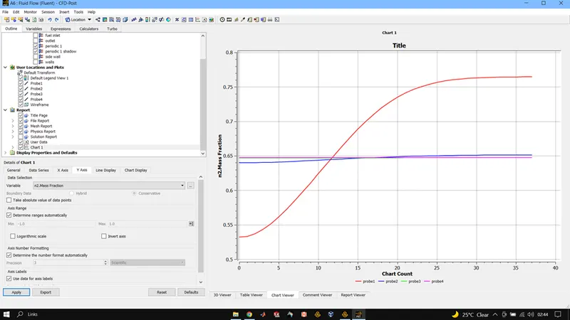
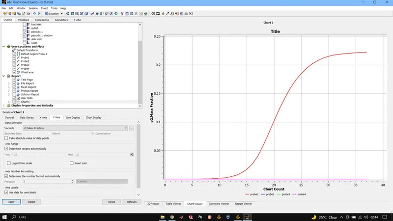
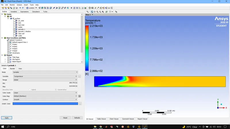
CH4 = 0.70, H2O = 0.30, 02 = 0.21 (MOLE FRACTION WISE)
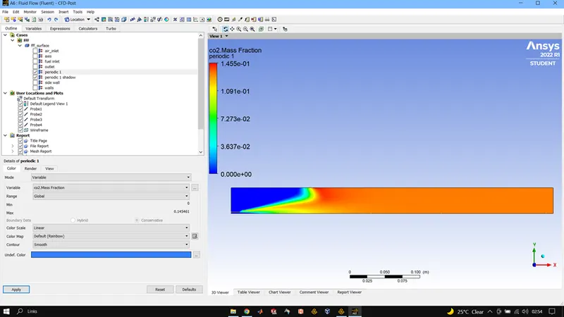
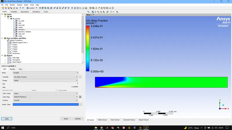
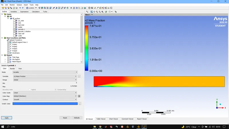
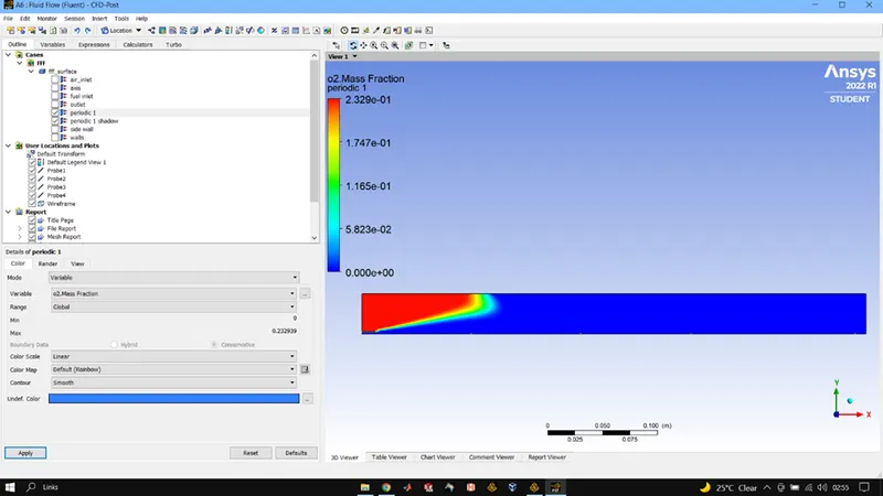
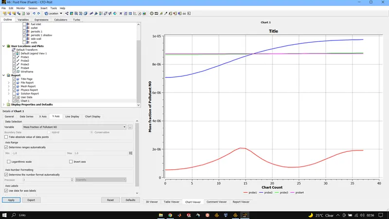
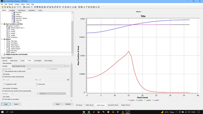
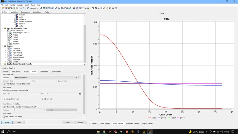
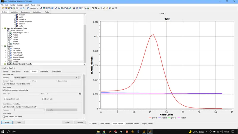
CONCLUSIONS:
When no water was added with the fuel
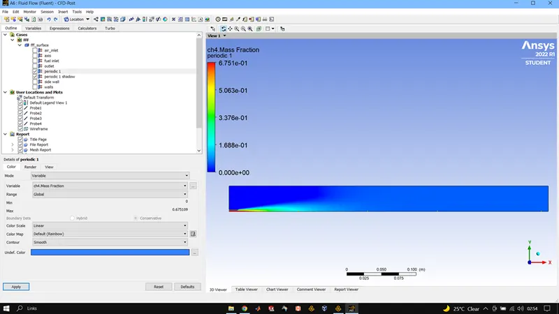
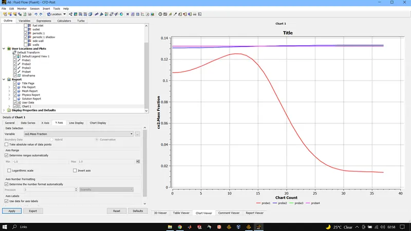
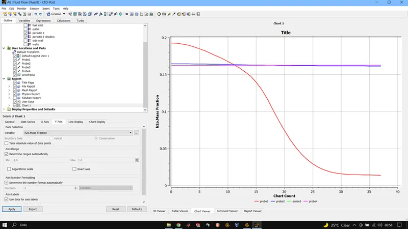
CH4 mass fraction was observed to be highest at the inlet where as CO2 and H2O attained their highest in the high temperature region after the combustion of fuel.
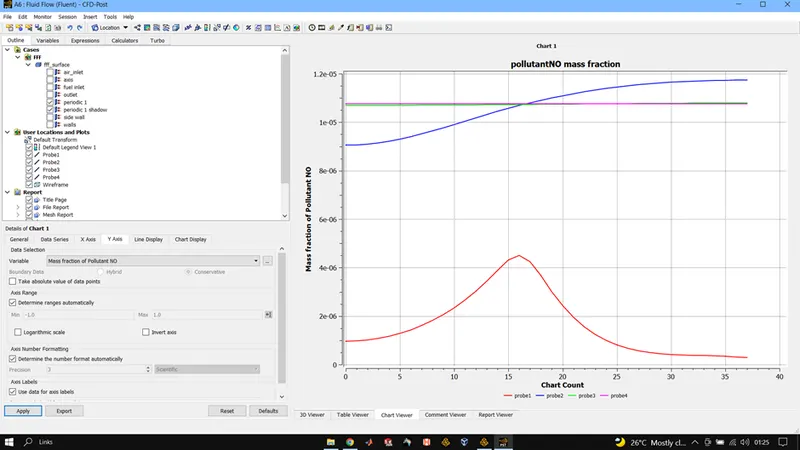
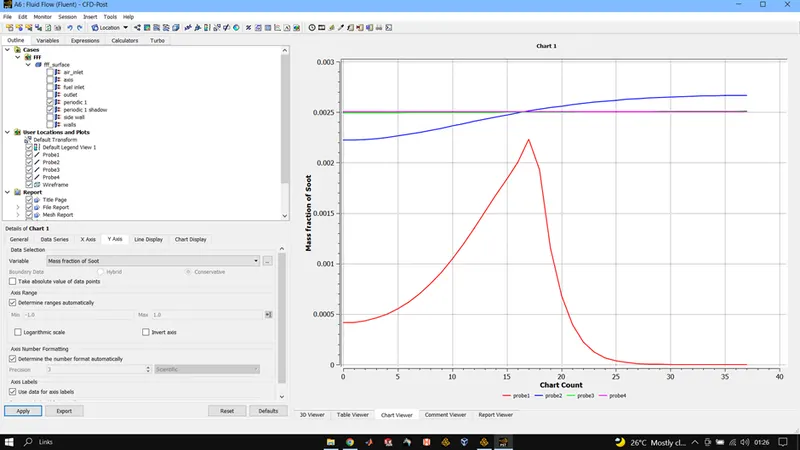
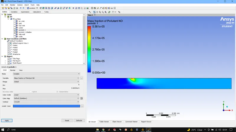
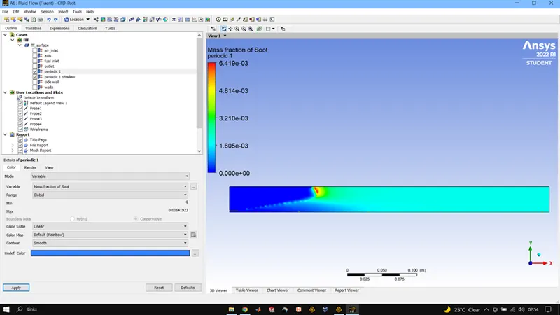
We also observe high concentration of NOx and Soot at the outlet of the burner chamber.
When water was being added in the fuel
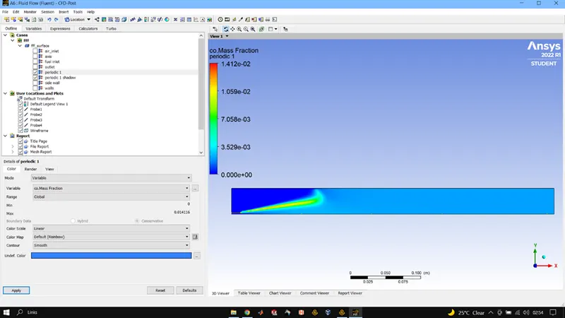
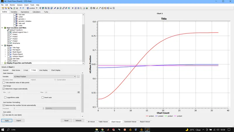
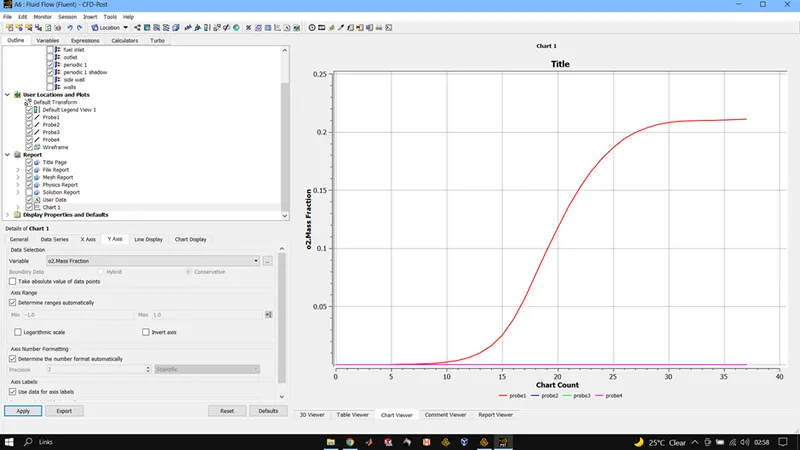
With increase in amount of water being added into the fuel we observe fall in highest temperature values. Though mass fraction of CO on the other hand shows increases as the amount of water increases. We don’t see significant variation in mass fraction N2 and O2.
We observe mass fraction of the pollutants like NOx and soot to fall with increase of water in the fuel.
In all we can say that the amount adding water into the fuel certainly helps in reducing the production of pollutants like NOx and Soot but we need to be careful with the amount being added as with increase in the amount we do see in fall of NOx and soot but on the contrary, we also observe rise in CO which displays incomplete combustion of the fuel. We also fall in temperature peaks which maybe indicative of less power generation due to combustion on increment of water percentage in the fuel.