Design and Development of the B- pillar (Interior Trim)
DESIGN AND DEVELOPMENT OF THE B-PILLAR (INTERIOR TRIM)
Automotive trims(interior and exterior):
Trims are the plastic parts installed on the inside and outside of a car. The interior trims are usually used for giving the aesthetic look to the interior of the car. There are various types of trims used in automobiles
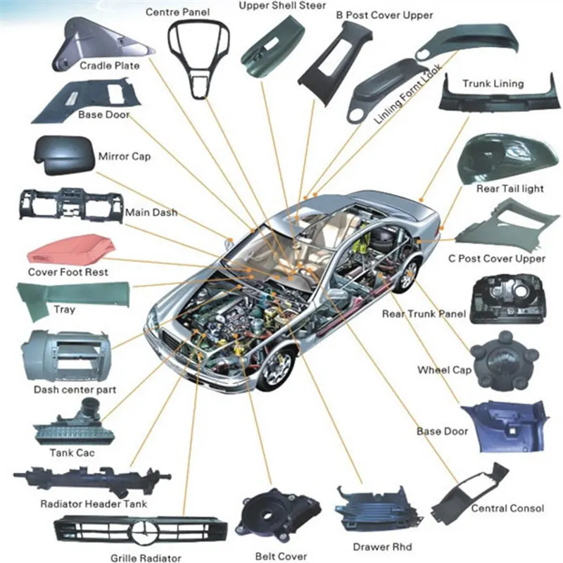
Fig 1 Different plastic trims used in a car
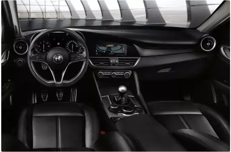
Fig 2 Instrument Panel of a car (interior trim)
Functionality and aesthetically pleasing trim applications are crucial factors for a perfect interior experience and successful vehicle sales. The selection, design, and processing of plastics solutions for interior trim components are very important for consumers when making their purchase decisions.
Trim applications require a variety of essential plastic material properties:
- High-quality aesthetics and haptics
- Reliable stability and long-term durability
- Ability to withstand UV light and exposure to high temperatures
- For load-bearing trim parts: enhanced stiffness retention at elevated temperatures and high dimensional stability
- Tight fit if assembled with other interior components/materials
- Impact resistance and good ductile performance at low temperatures, especially with safety-related components (airbags, passenger restraint systems)
B-pillar
The B-pillar is the central pillar of the car. This pillar is actually a sheet metal part which is welded in the BIW of the car. The B-pillar trim is attached to the B-pillar and improves the aesthetic look of the car. Mostly the trims are manufactured by the injection molding process. The design of the B-pillar is carefully done to make the part manufacturable and usable in the interior. While manufacturing a part through injection molding a lot of defects can occur on the plastic part which will destroy the look of the panel. The design has to made in such a way that all the errors can be rectified.
Fig 3 Pillars in a car
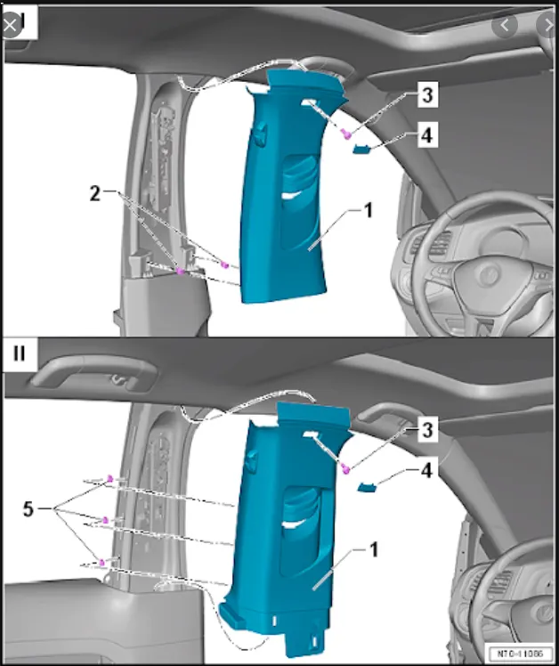
Fig 4 B-pillar trim ( upper trim(left) lower trim(right)
OBJECTIVE:
- Create a closed body of the Given B pillar
- Crete tooling axis and follow design rules.
- Follow the Master section to create a flange
- Follow the master section for thickness and to create the Closed volume.
- Follow the master section to create Attachment features.
GIVEN:
- A-surface
- Master sections
- Distance between ribs should be 50mm
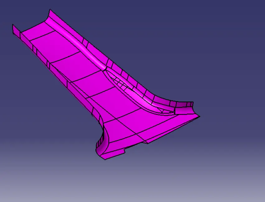
Fig 5 B-pillar styling surface
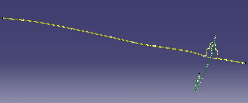 Fig 6 Master sections
DESIGN METHODOLOGY : - A-surface improvement.
Before we start creating the closed body for the B-pillar we need to check the quality of the given A-surface. The A-surface needs to be free of all the patches or error elements. For this first, we need to disassemble the given styling surface and join it with the merging distance of 0.001mm.
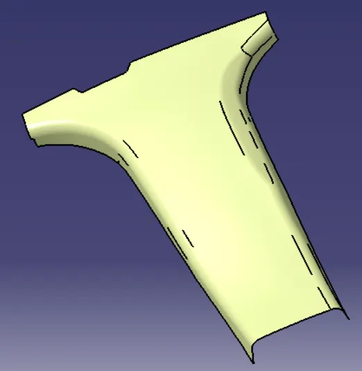
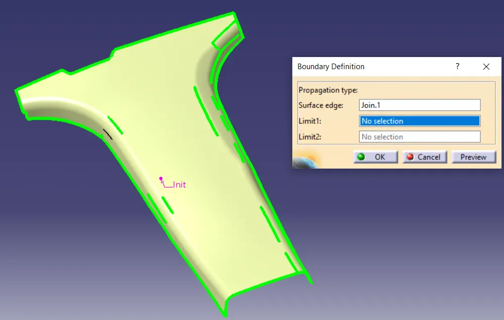
Fig 7 Surface quality of the surface Fig 8 Using boundary command we can check the openings in the surface

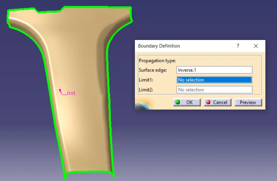
Fig 9 A-surface Cleanup
- Flange creation
According to the master section, the B-pillar has flanges on both sides. The flanges have to be included in the design and the A and B surface has to be modified. The surfaces should match the master section.
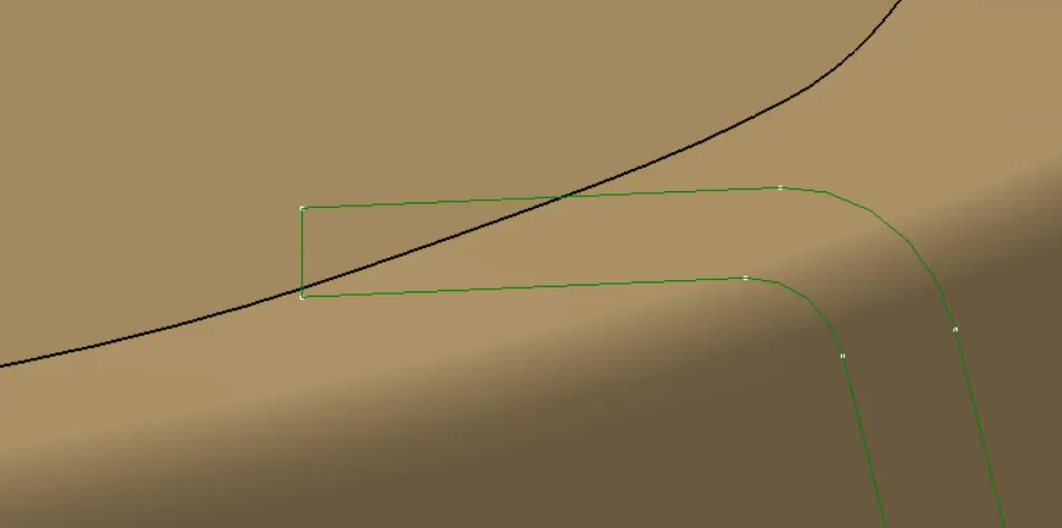
Fig 10 A-surface flange with master section.
- Main Tooling Axis Creation:
The tooling axis is the direction in which the core moves. During injection molding the core is moved into the cavity and molten plastic is injected. When this molten plastic is cooled down then the core is moved away from the cavity. The direction in which the core moves is the tooling direction for the part.
To find the tooling direction we use the mastersection for the engineering feature. Here we take the two boundaries and find a bisecting line between them.
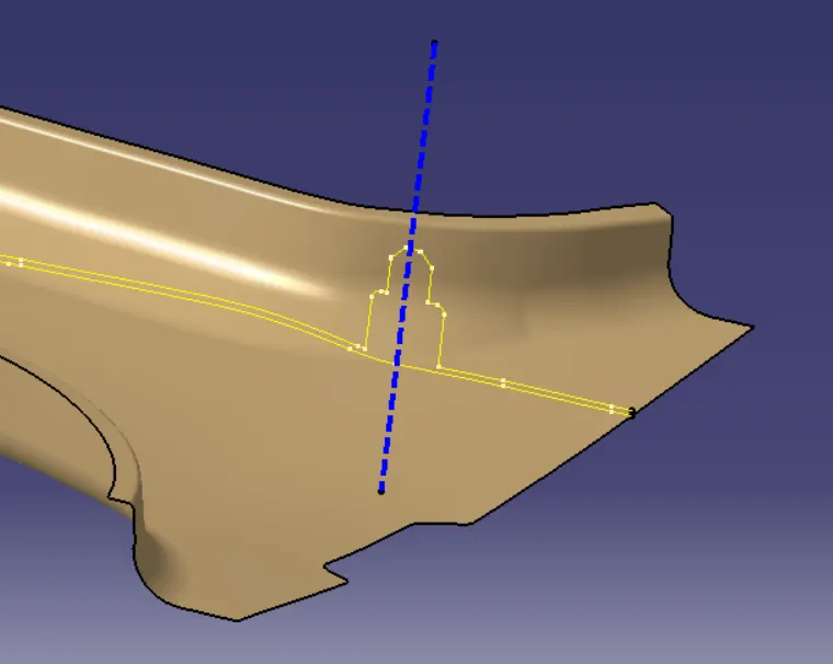
Fig 11 Main Tooling Direction
- Manufacturing Feasibility of the A-surface (Draft analysis):
Draft analysis is used to check the A-surface manufacturing feasibility. The tooling axis is used as a reference. Draft analysis checks the angle at which the surface is with respect to the tooling axis. As we know for injection molding the draft on the surface should be positive and greater or equal to 3 degrees. Areas with the draft less than 3 degrees are a bit difficult and costly to manufacture.
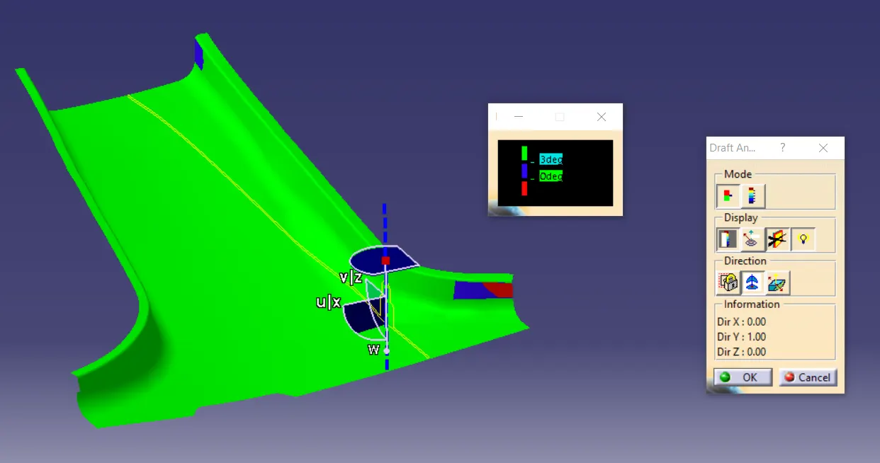
Fig 12 Draft Analysis on the A surface for 3 degrees
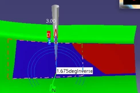
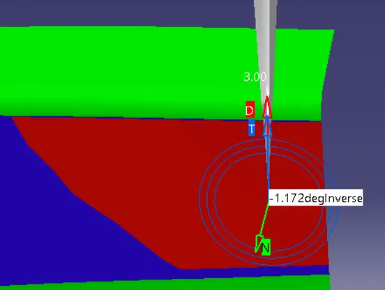
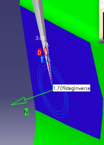
Fig 13 Draft analysis on the A surface problem areas
The styling team is informed about the errors in the A-surface and the draft analysis report is sent.
- B-surface creation:
Accor ting to the master section the offset value for the B-surface is 2mm. We offset the A-surface and create the B-surface at 2mm offset. The offset will result in some areas having a problem. We need to rectify the patches and create a smooth surface.
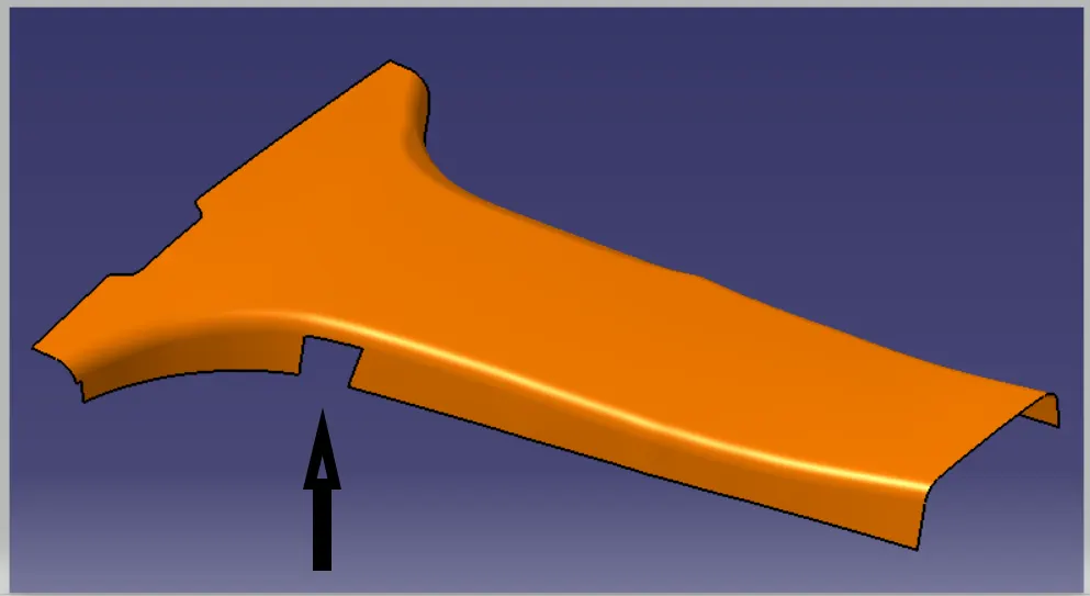
Fig 12 B-surface patch
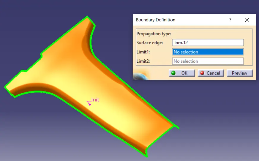
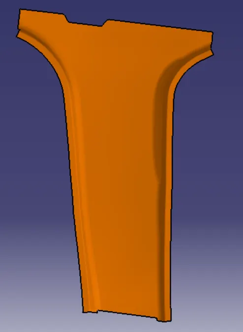
Fig 13 B-surface improved Fig 14 B-surface with flange
- Closing surface :
The closing surface of the plastic part should be created in such a way that it follows the draft of the A-surface. This is necessary to maintain the A-surface finish in the injection molded part.
One of the most common defects in plastic parts is flash. Flash is the extra material that is stuck on the molded part which has to be removed in order to achieve the proper shape. If this part occurs on the A-surface then it will affect the aesthetics of the part. Due to this, we need to make the closing surface in such a way that the B-surface is outward
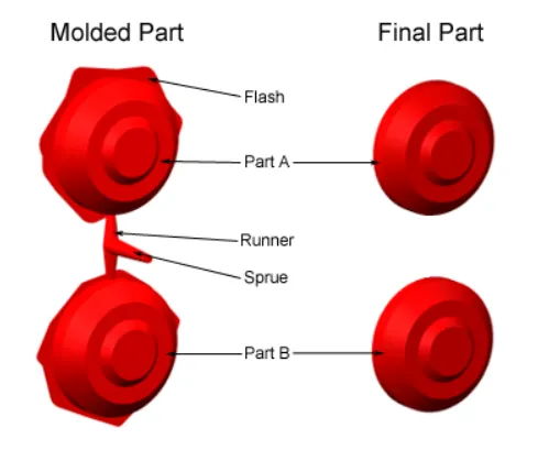
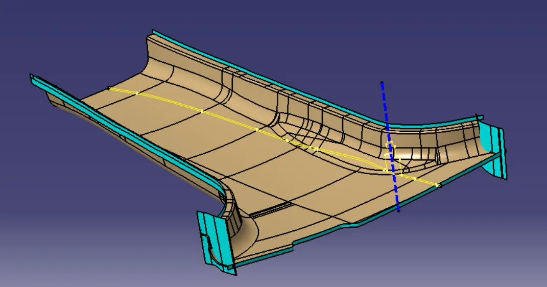
Fig 15 Flash (plastic defect ) Fig 16 Closing surface at angle of 3 degrees with respect to tooling direction
- Closed body and Draft analysis
A closed body is developed from the above surfaces and a check was performed on the body to find any openings in the surfaces.
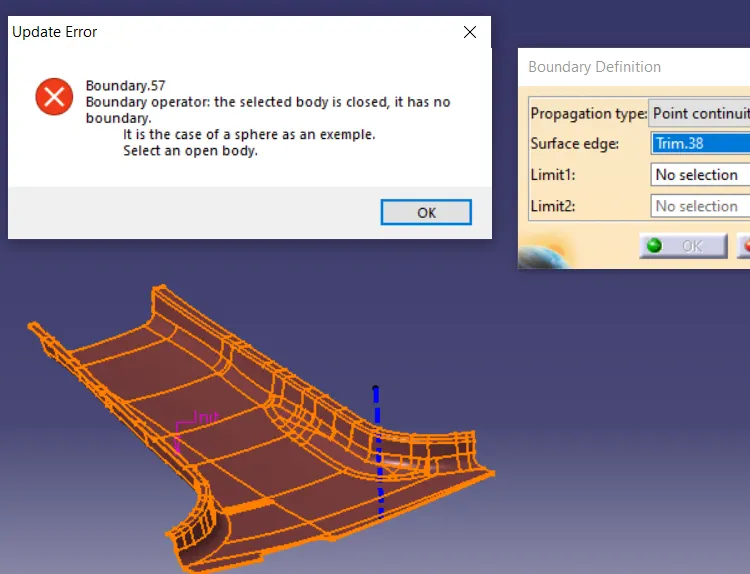
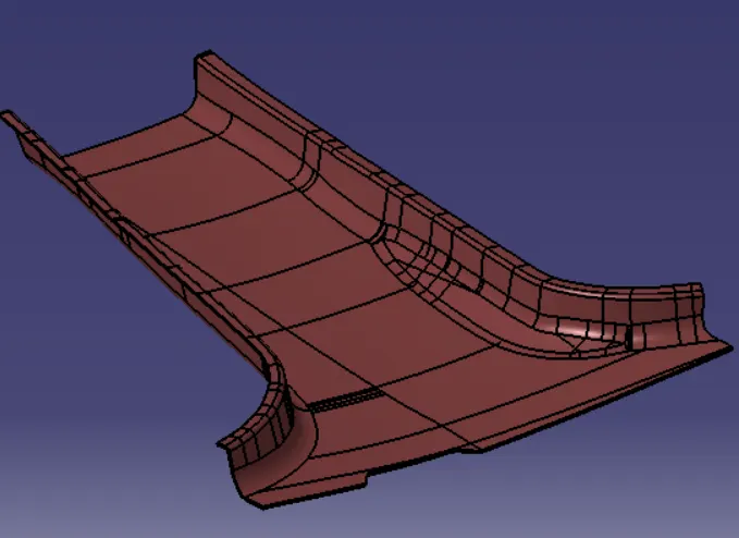
Fig 17 Closed body of the B-pillar
Draft analysis:
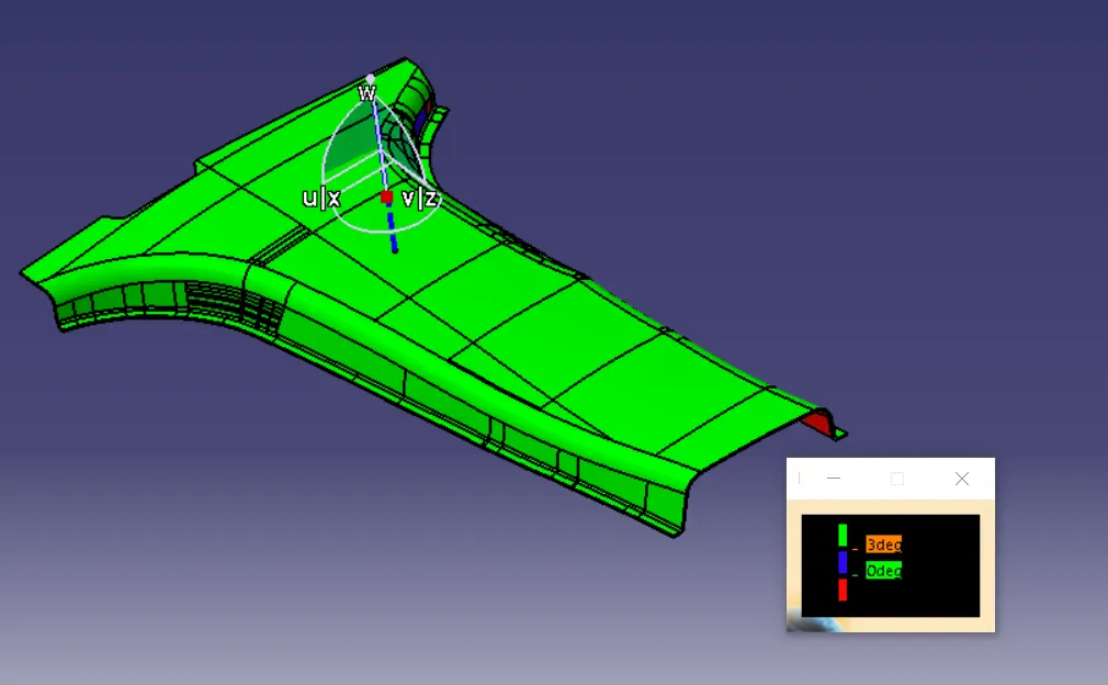
Fig 18 Draft analysis on the body for degrees
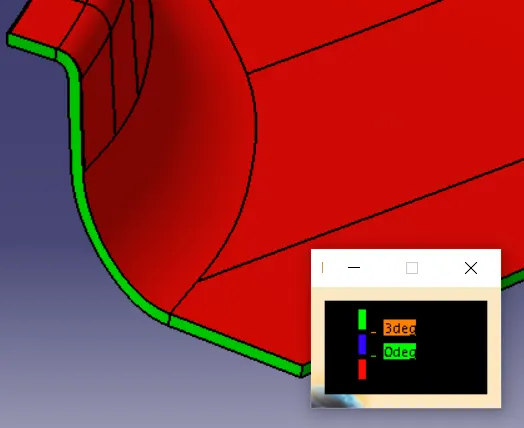
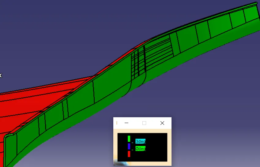
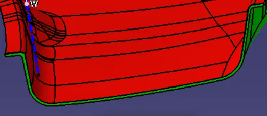
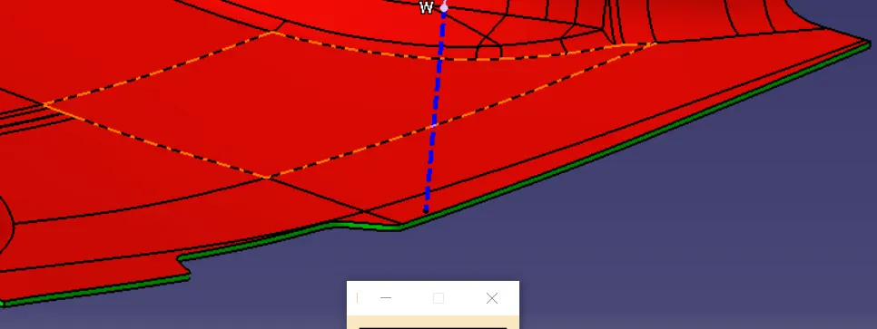
Fig 19 Draft analysis on the closing surface (the closing surface follows the A-surface draft)
- Parting Line
The parting line is created when the core and cavity meet, the space between the junction where the plastic flows creates the parting line.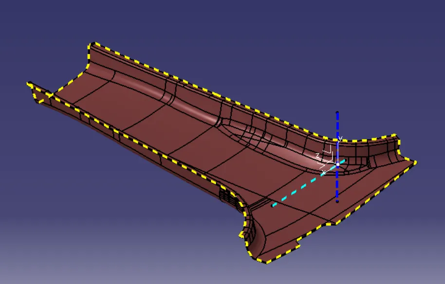
- Attachment feature creation :
The attachment features will be created according to the input given to us. According to the master section, we have a dog-house and a 4-way locator on top. First we need to create the dog house.
The dimensions of the dog house and the four-way locator are taken from the master section.
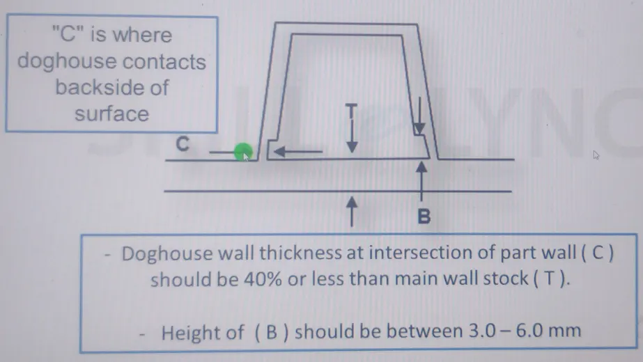
Fig 20 Dog house design guidelines
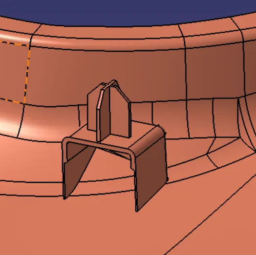
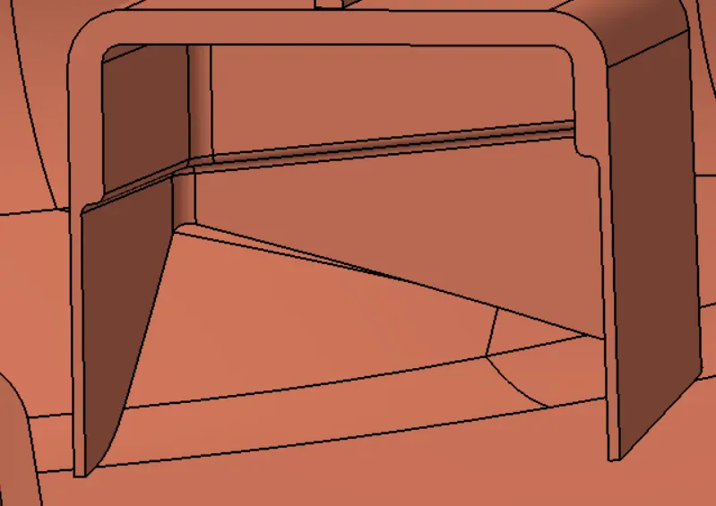
Fig 21 Dog house with locator Fig 22 Undercut in the dog house
Slider Tooling Axis for the Dog house:
The dog house's inner walls will not be cleared in the main tooling direction. For this, we need to make the tooling axis for the Slider. A min of 0.5 degrees draft is provided on all the walls.
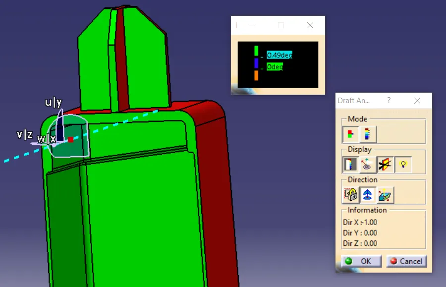
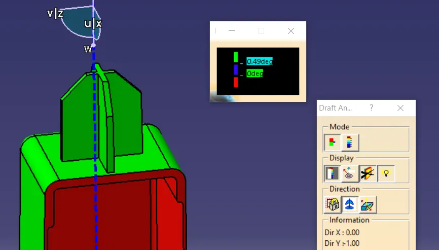
Fig 23 Draft analysis on the dog house inner walls Fig 24 Draft analysis along the main tooling direction
Ribs creation :
Ribs guidelines
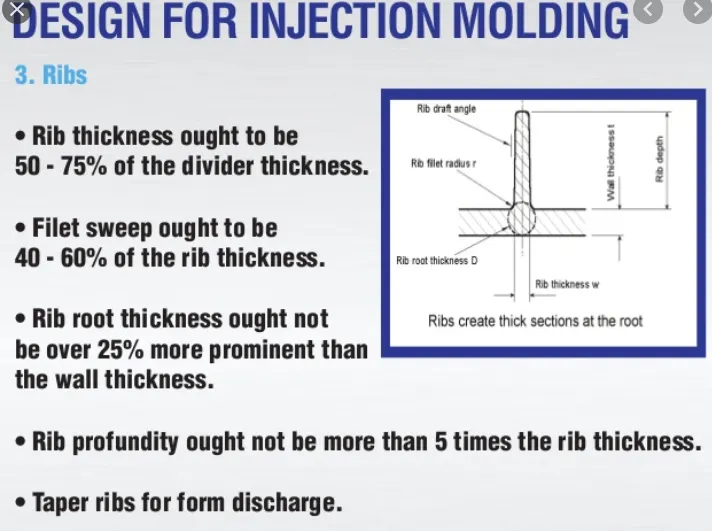
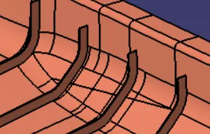
Fig 25 Rib design guidelines Fig 26 Ribs on both sides at 50 mm distance apart
Draft analysis on the ribs
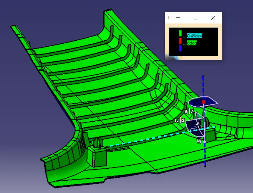
Fig 27 Draft analysis on for 0.49 degrees ( only for engineering features)
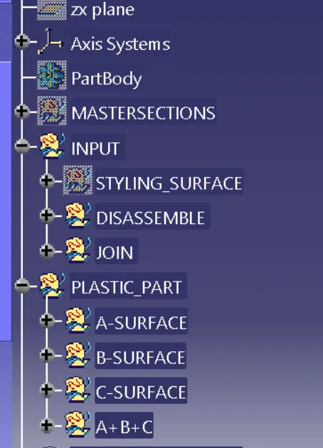
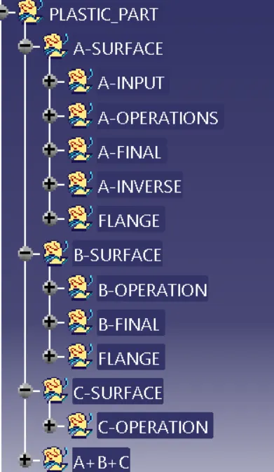
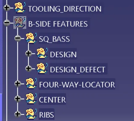
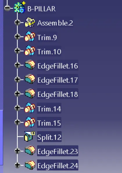
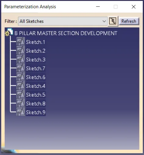
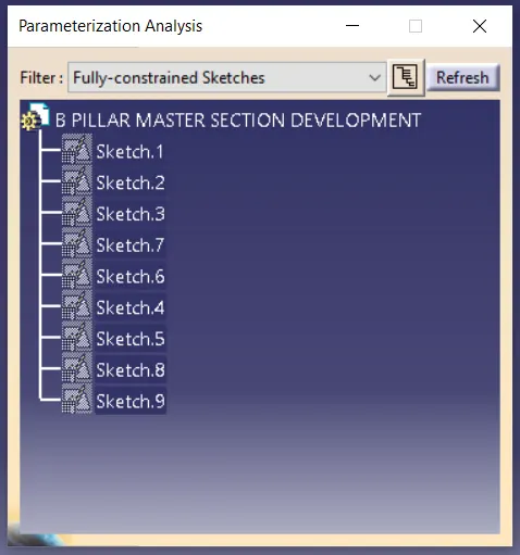
TREE MAINTENANCE:
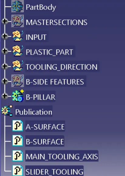
FULLY CONSTRAINED SKETCHES
FINAL DESIGN
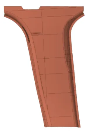
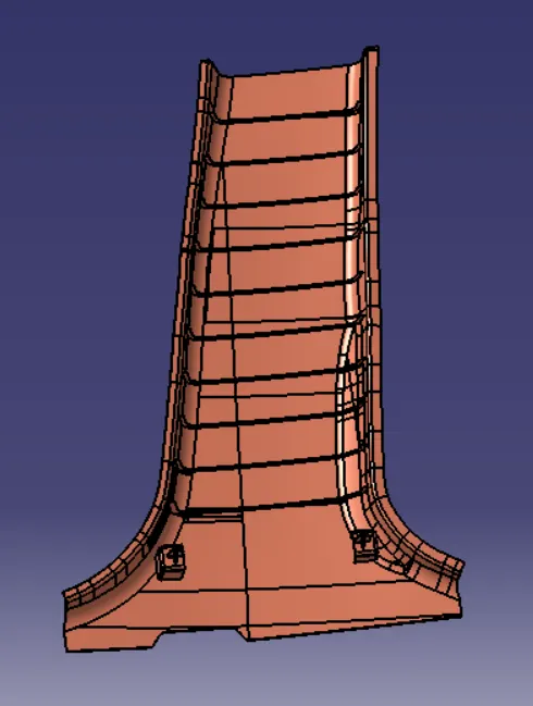
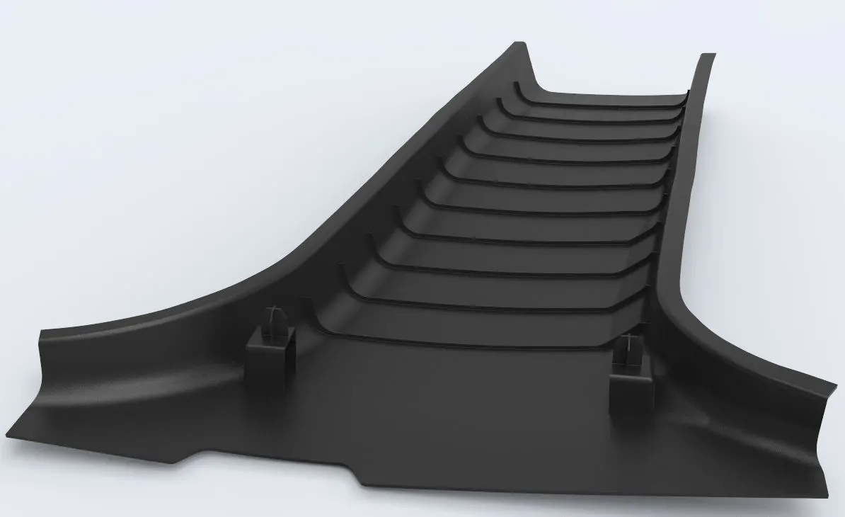
Fig 28 B-pillar designed in CATIA V5 rendered in Keyshot 9
CONCLUSION
The B-pillar was designed for the given A-surface and master section while following all the plastic guidelines in the process.