Design of Car Fender from the given A-surface using CATIA V5
DESIGN AND DEVELOPMENT OF CAR FRONT FENDER
INTRODUCTION
Fender is a BIW component used as a frame for the wheel, the main purpose of a fender in an automobile is to protect the engine compartment from sand, dust, small stones, etc which are thrown into the air by the tire grip. These can cause damage to the car body and hence we use a fender to guard the tire. We have front as well as a rear fender in a car, the rear fender is integrated with the body side. The front fender is a separate closure commodity.
There are two types of the fender in general:
- full bumper type
- half bumper type
Full bumper type :
The full bumper type fender was used in old cars, it covers the full area until the front lighting. But it has a lot of sheet metal material which is unnecessary and increases the weight of the fender. These type fenders are no longer used in the automobiles.
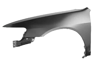
Half bumper type :
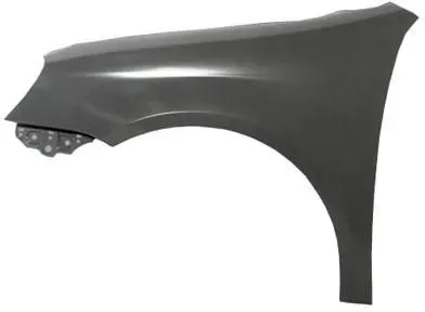
Fender Mounting Parts:
A fender has a total of 5 mounting points through which it is mounted in a car. These are
- Sill mounting
- Splash Cover mounting
- Bumper Mounting
- Drip area
- A-pillar mounting
Given:
Fender Styling Surface and Drip area Master section
Setting up the origin and the Styling surface:
Before we start the designing of the components we have t follow certain requirements such as
- We should not use the default planes and part body for modeling
- Setup the origin point and an axis system, link this axis system with the origin point
- Maintain the tree structure.
- All the sketches should be iso-constrained and linked with one point and one plane.
- No link should be there with the Styling surface.
A-surface cleanup:
The given styling surface has to be checked for any patches that might be present which will hinder in later stages of the cad model development. To check the A-surface we first go to the respective View environment (shading with smooth surface). Here we ensure that when we perform the Join operation then we should have the 0.001 mm gap between the surfaces
Creation of Mounting Features :
- Sill mounting
- Drip Area
- Baffle mounting
- Bumper Mounting
- A-pillar Mounting
- Fender with all five mounting points: