Design of Car Backdoor Inner panel
DESIGN AND DEVELOPMENT OF BACKDOOR USING CATIA V5
INTRODUCTION :
Backdoor/tailgate is one of the closure commodities in BIW sheet metal design. The backdoor has a lot of components inside and is designed to incorporate them easily. It affects the rear visibility and luggage area.
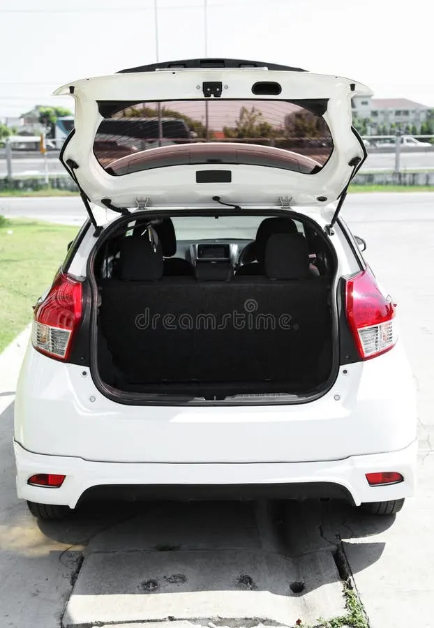
Fig 1 Car Tailgate
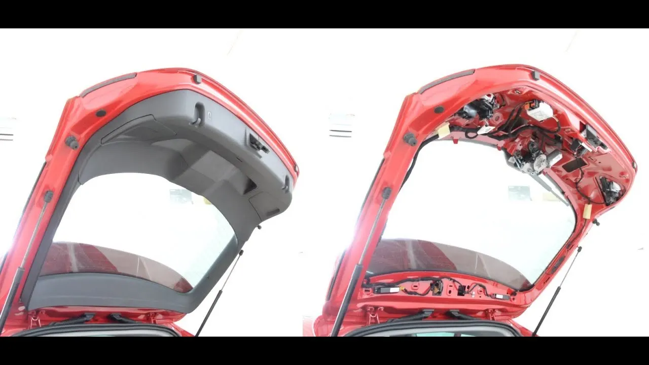
Fig 2 The back door of a hatchback (with and without trim panel)
The backdoor consists of the following basic components:
- Backdoor inner panel
- Back door outer panel upper
- Back door outer panel lower
- Hinge reinforcements
- Gas-stay reinforcements
- Latch and striker reinforcement
- Wiper motor reinforcement
OBJECTIVE
- To design the tailgate inner panel, outer panel(upper and lower).
- Perform draft analysis on the inner panel
- Design all the necessary reinforcements.
SOFTWARE USED: CATIA V5
DESIGN PROCEDURE :
- Styling surface cleanup: It is necessary to check the given styling surface before using it to create the cad model. This is done to check the continuity in the skin surface as sometimes the distance between the surface is more than 0.0001 mm.
Fig 3 Styling surface for backdoor
- Surface simplification: This is done to achieve a smooth edge surface as it will be better to perform complex operations on the surface. All the erroneous elements are removed and a smooth surface is obtained( Note: I had permission from my course instructor to change the A surface, the designers are not allowed to change the A - surface.)
Fig 4 Extracted surface Fig 5 Smooth surface
- Design guidelines followed :
While designing the cad model we have to follow certain guidelines such as - We don't use the default planes and part-body in CATIA V5.
- All the sketches should be constrained and linked to one plane and one point.
- No link should be there with the A-surface.
- Specification tree maintenance is necessary.
Fig 6 Specification tree Fig 7 Fully constrained sketches
- Design of inner panel:
For designing the inner panel we develop the flange with the use of different sections. These sections are created randomly and then dimensioned accordingly to get the right shape. The length and depth of the ceiling flange are defined by these sections. Then keeping the luggage area in mind we decide the panel depth on the lower side.
Fig 8 Development of the inner panel - Emboss Creation: The embosses on the panel are created in order to provide strength to the component and remove material from the panel. The shape of the emboss is decided by the load test cases results. The backdoor is subjected to various load cases such as bending, torsion, abuse cases (impact) etc.
Fig 9 Load test on inner panel
From these tests, the most vulnerable areas to the impact force were observed. This helped in designing the shape of the embosses and providing necessary reinforcements in the pannel.
Fig 10 Most affected areas
To provide strength and to distribute the impact force at the latch and striker area I have provided V-shaped emboss on the panel. Also, the place near the latch and striker is provided more material.
Fig 11 Embosses on the panel - Holes and flanges for the trim panel:
The trim panel covers the inner panel from inside and give a classy look to it. These panels are connected via clips and pins to the panel, also flanges at the window area are provided to insert properly in the plastic trim.
Fig 12 Backdoor Inner panel and plastic trim part
Also in the above figure, we can see the wires that go through the panel so we have to provide openings to make the routing easier.
- Inner panel flange, hinge, and gas stay emboss:
The inner panel flange is used to join the inner panel and outer panel using mastic glue. This is done to avoid rattling noise.
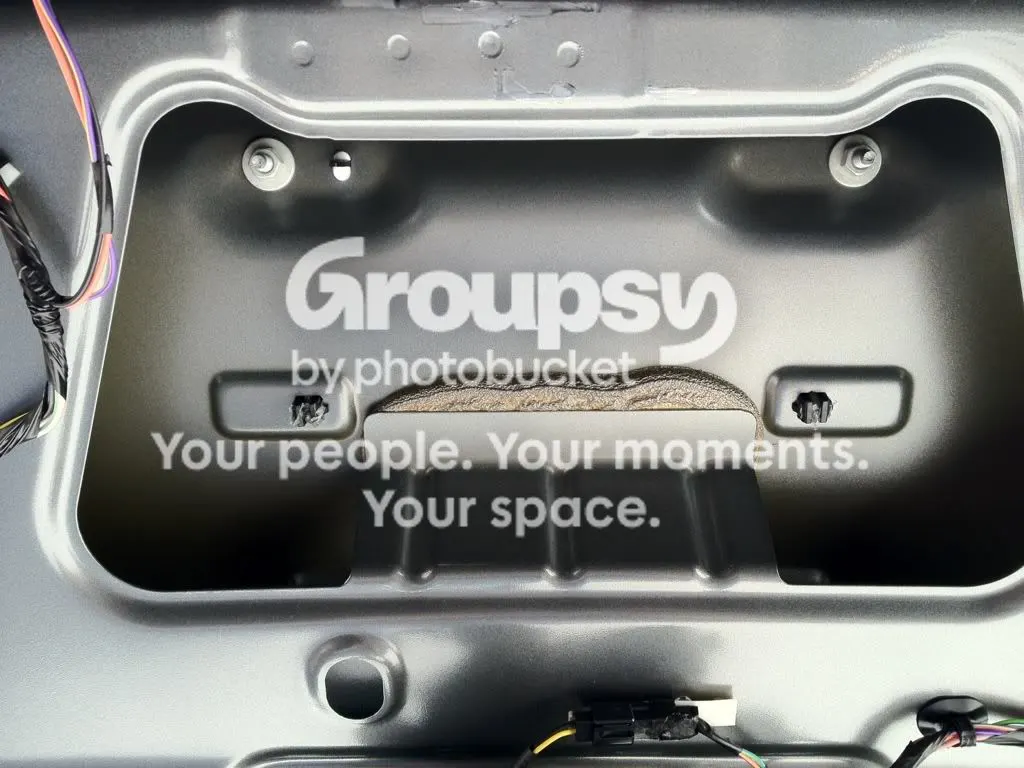
Fig 14 Inner panel flange stuck to the outer panel using mastic
Fig 15 Inner panel (front View)
Fig 16 Inner panel (side view) - Reinforcements: We have to provide necessary reinforcements to strengthen the component at the functioning areas like the hinge, gas-stay and latch & striker.
All the reinforcements are 1 mm thick.
Fig 17 Inner panel reinforcement - Outer panel(lower & upper) :
The thickness of 0.75 mm
Fig 18 Outer and inner panel
Fig 19 Outer panel hem on the inner panel with relief. - Draft analysis: Draft analysis is done to check whether the part is manufacturable or not. It is not a sure-shot confirmation that the part is manufacturable but it is used to check the draft angle on the
part. - The draft angle is taken as 7mm.
- The tooling direction for the analysis is perpendicular to the wiper motor area
Fig 20 Draft analysis on the Backdoor - Hinge axis and striker position study :
As we know that backdoor is a swinging commodity we have to position the striker correctly. This can be done by tentatively positioning the hinges and on the hinge axis, we take a center point. again we take another center point(approx) on the latch hole. Taking these two points as a reference we draw a circle. This circle is the striker trajectory and it has to be perpendicular. This can be achieved by moving the hinge axis back and forth or by rotating the latch area.
Fig 21 Hinge axis center point
Fig 22 Striker trajectory - Final Assembly
- CONCLUSION: The design of the backdoor BIW was completed with all the necessary reinforcements