Week 10: Project 1 - FULL HYDRO case set up (PFI)
FULL HYDRO case set up (PFI)
Aim:-
- Modify the last setup to Full hydro simulation.
- Set the parameters for Spray modeling, Combustion modeling, and turbulence modeling.
- Find out compression ratio.
- Specify whether using this simulation wall heat transfer could be calculated or not.
- Calculate the combustion efficiency of this engine.
- Use the engine performance calculator, to determine the power and torque for this engine.
- State the significance and meaning of the significance of ca10, ca50, and ca90.
- Finally, create an animation of woking ic engine.
Continued from the last Project:- Project 1 - Surface preparation and Boundary Flagging (PFI): Skill-Lync
In the last project, we set up the simulation to check the computational mesh with no hydro model. But in the process of setup, we did not set the fuel spray, the combustion, and the turbulence model.
Now, in this project, we have set up the proper spray model and turbulence model by setting it up with a full hydro combustion model.
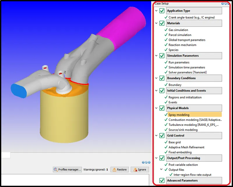
Materials
Select the parcel simulation option from materials to define the fuel for the IC engine.
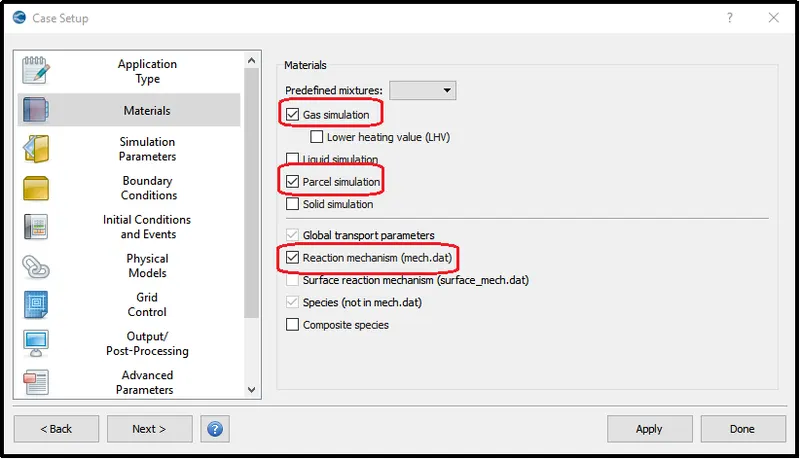
Parcel Simulation:-
From the liquid database select IC8H18. IC8H18 is named iso-octane which has a physical property very similar to our gasoline fuel. So in this case depending upon the fuel user has to select the right species. While selecting the fuel, the physical property of the selected partial species must mach with the physical property of the actual fuel. Users can find the property of the selected fuel in the converge specification box - viscosity, surface tension, vaporization, vapor pressure, conductivity, and specific heat as a function of temperature.
If the user selects the wrong species for the simulation, it will affect the results of the simulation. In this case, the spray prediction might be off. For instance, the viscosity of the fuel that chosen is different than the viscosity of fuel used in the experimental setup. Then the automization of the fluid in the simulation setup will be different from the experimental data which means the rate of vaporization will also be different. And this leads to different combustion phenomena as compare to actual simulation. Therefore, selecting the correct fuel property is extremely important.
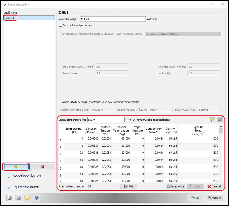
Species:-
Now, in the species section, the selected partial species was defined. Here, we did not need to define all the species that we are using as we already defined it in the reaction mechanism. We only have to define the liquid species from the partial species.
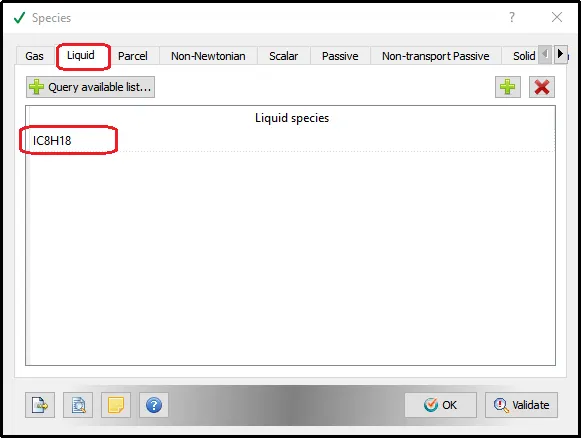
Physical Models:-
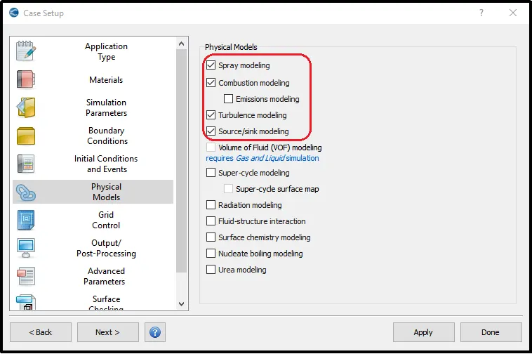
Next, in physical modeling, the spray modeling and combustion modeling option was enabled.
Spray Modelling:-
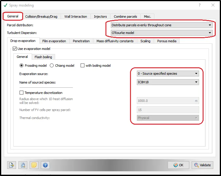
Parcel Distribution:
In parcel distribution, the Distribution parcels evenly throughout the cone was selected to get the proper distribution from fuel spray.
Turbulent Dispersion:
CONVERGE offers the O’Rourke, Kuhnke, and Bai-Gosman film splash models. For after-treatment simulations, the Kuhnke model is commonly used. By altering model parameters like the rebound Weber number and non-dimensional critical wall temperature, you can alter model parameters to correlate the model to experimental results. The Wruck heat transfer model is also available to account for the Leidenfrost effect.
Here, the O’Rouke model was selected for this gasoline combustion simulation.
Evaporation source:
For the Evaporation source, the source specified species option was chosen.
Injection Configuration:
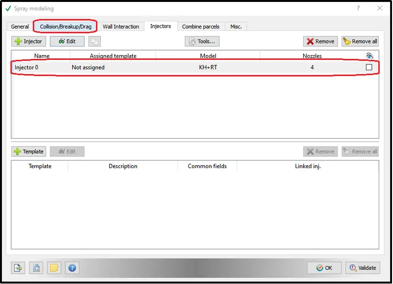
To configure the injection parameter add the injection parameter in the injectors section.
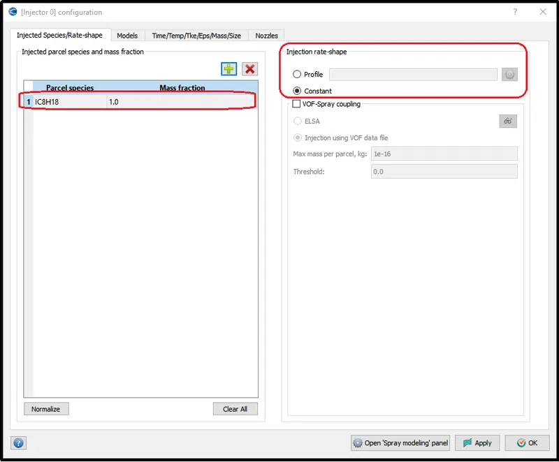
Injector Species and Rate-shape:-
Here we are going to provide our liquid fuel in the parcel species column and We can set the injection rate shape or we can keep it constant.
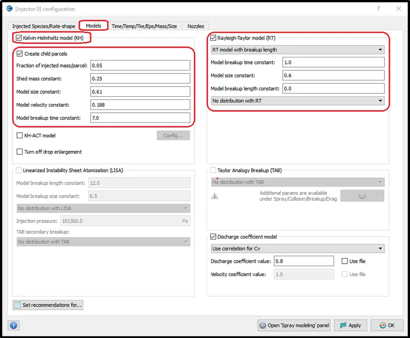
Models:
Enable create child models and Rayleigh-Taylor model (RT) and all other condition was kept default.
The above-selected constants control, how the parcels going to break up. So in the Rayleigh-Taylor method, there is an equation called a stability equation or dispersion equation that calculates how long it will take for dispersion of the parcels.
Finally, use a set recommendation for the option to set the required recommended parameter for the selected fuel.
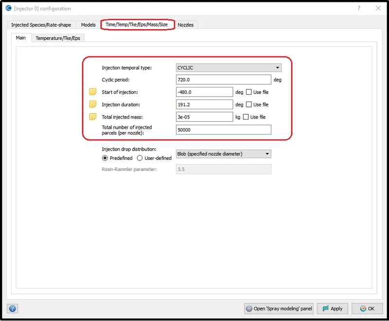
Time/ Temperature / mass/ size:-
Following parameters was set for Time/Temperature/mass/size option.
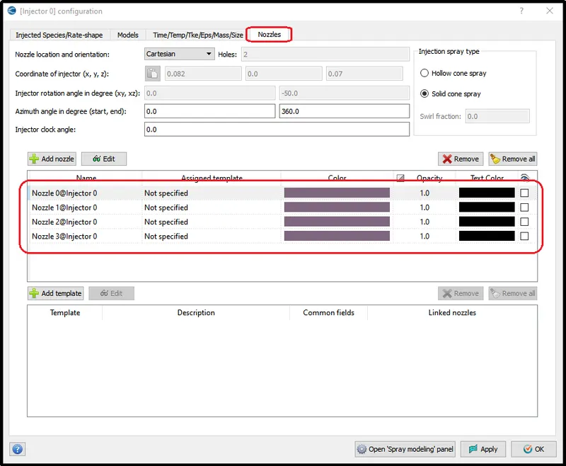
Nozzles definitions:-
Four Nozzles were created using following nozzle parameters:
Nozzle diameter = 250 micro-meter
Circular injection radius = Nozzle radius
Spray cone angle = 10
- Nozzle 0
- center 0.0823357 0.00100001 0.07019
- Align Vector -0.732501 0.210489 -0.647408
- Nozzle 1
- center 0.0823357 -0.00099999 0.07019
- Align Vector -0.732501 -0.210489 -0.647408
- Nozzle 2
- center 0.0823357 -0.0004 0.07019
- Align Vector -0.5 -0.2 -0.647408
- Nozzle 3
- center 0.0823357 0.0003 0.07019
- Align Vector -0.5 0.2 -0.647408
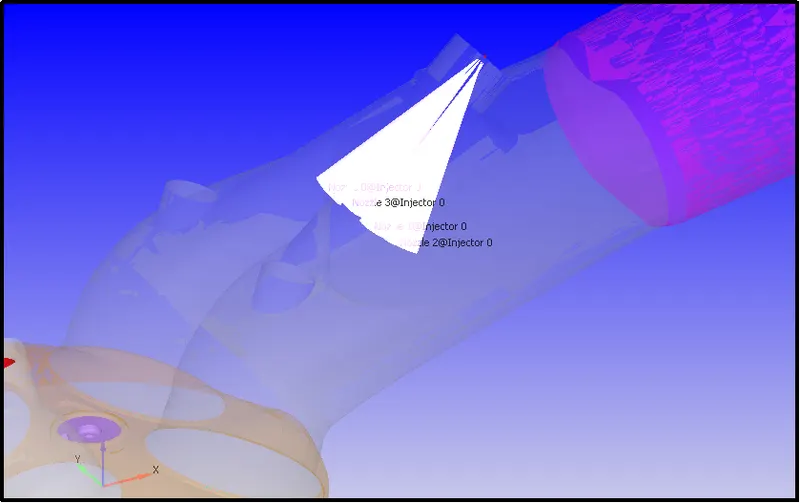
After Setting up the setup for Nozzle parameter converge will show you the following representation in GUI.
Combustion modeling Setup:
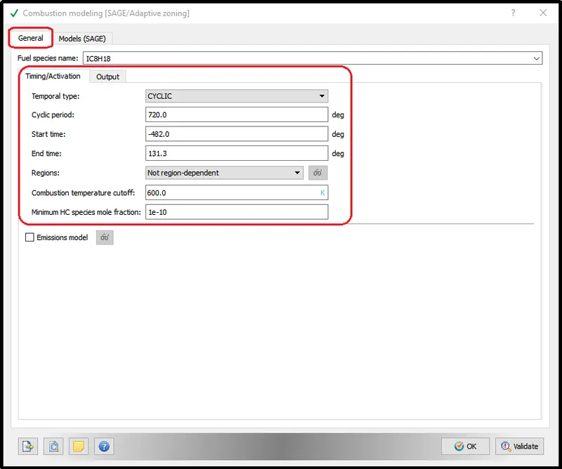
In the combustion modeling setup, the information for the Cyclic period, Start time, End time, Regions was provided as shown in the picture.
Source/sink modeling (Spark Setup):-
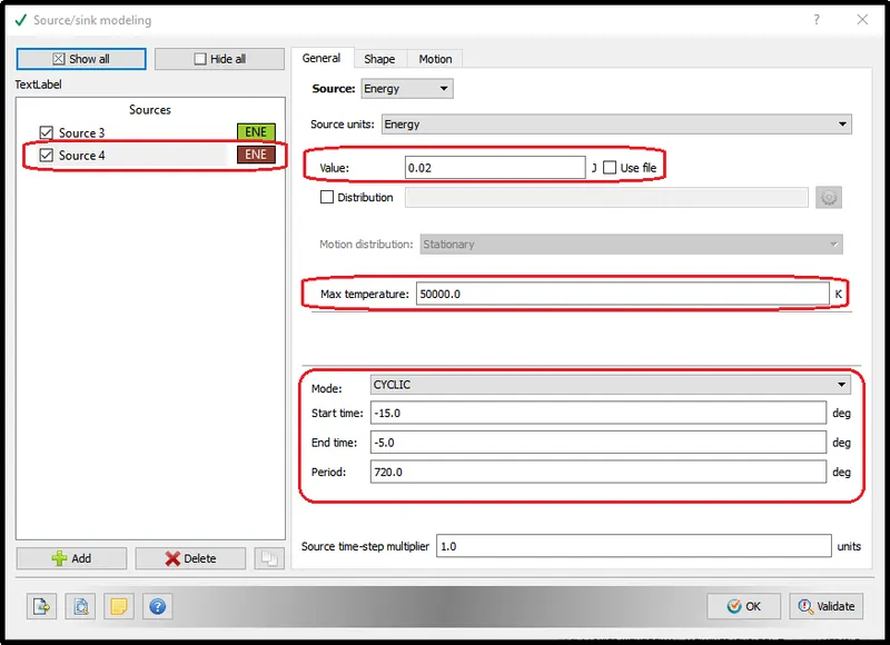
- In this part of the setup, the two spark setting was set up on with 40mJ energy and another one is with 20mJ energy.
- If we observe the energy release in the IC in the engine from experimental data the real spark is broken down into three phases breakdown, arc, and glow. During the breakdown phase, we put more energy so that we can conduct the spark gap.
- Once we achieve the breakdown phase, the engine needs a little bit more energy to keep the conduction going on.
- So it turns out that during the breakdown phase we provide 40mJ of energy that lasts for a little bit of time.
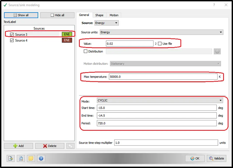
- And, that we provide 20mJ of spark energy.
- Therefore, we are adding two energy sources one with 40mJ of energy and another one 20mJ.
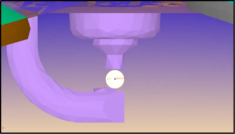
As demonstrated in below picture we will get both the spark energy in the same location.
Fixed Embedding for Spark Ignition:-
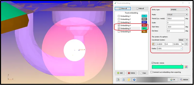
Two fixed embeddings were provided to capture the essence of the spark ignition in the simulation. One is with a smaller radius of 1mm and another one with a radius of 3mm.
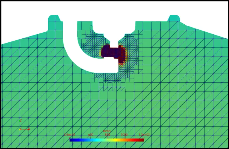
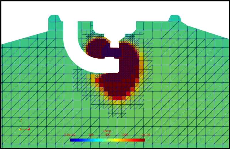
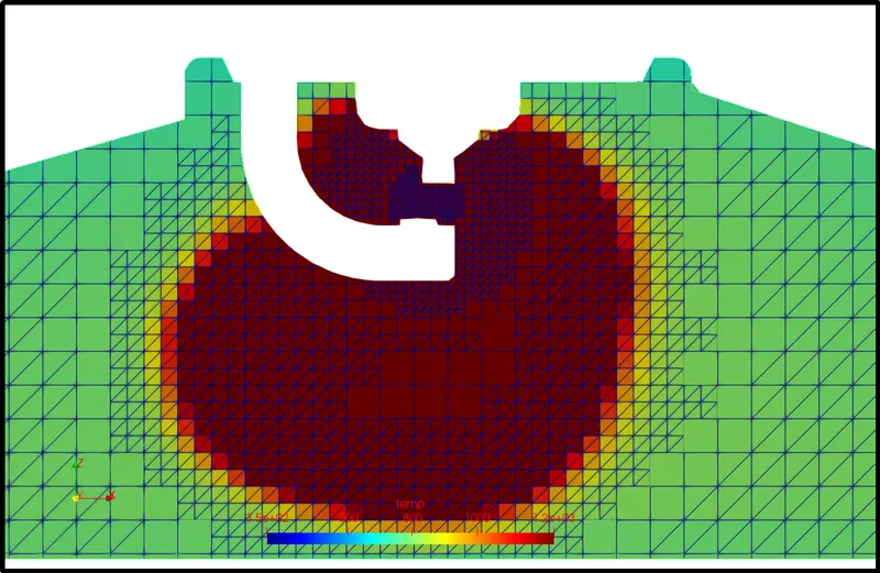
Actual Mesh representation:-
RESULTS:-
The Compression Ratio of an IC engine:-
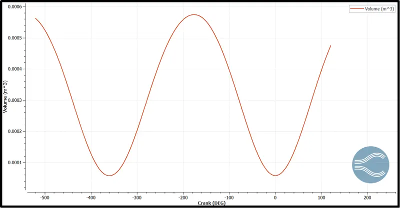
Compression Ratio = Maximum volume/ Minimum volume
Why do we need a heat transfer model?
- The ability to predict heat transfer in engines plays an important role in engine development.
- Heat losses are a major limiting factor for the efficiency of internal combustion engines.
- Furthermore, heat transfer phenomena cause thermally induced mechanical stresses compromising the reliability of engine components.
- In a simple world, one can simulate fluid flow and assume that the walls of the container were at a constant temperature or even adiabatic. In reality, however, the heat transfer between solids and surrounding fluids couples the temperature field in both materials.
- The accuracy of the predicted combustion in the cylinder is dependent on the temperature boundary conditions in the cylinder.
- By considering heat transfer in the metal components (e.g., the cylinder head, liner, piston, etc.), the cylinder wall no longer has a user-specified temperature but instead has temperatures predicted as part of the complete-system simulation. This makes the overall simulation results more predictive by reducing the dependence on assumed boundary conditions.
Why can't we predict the wall temperature from the CFD simulation?
- To predict wall heat transfer we have to do a CHT (Conjugate Heat Transfer) Analysis on the engine cylinder.
- The Conjugate Heat Transfer (CHT) analysis type allows for the simulation of heat transfer between solid and fluid domains by exchanging thermal energy at the interface between them.
- In solids, conduction often dominates whereas, in fluids, convection usually dominates.
- In this case setup, we are not considering the Solid parts, and simulation was only performed on the purely fluid domain, therefore with this setup, we can not predict the wall temperature.
Heat Rate:-
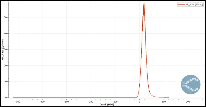
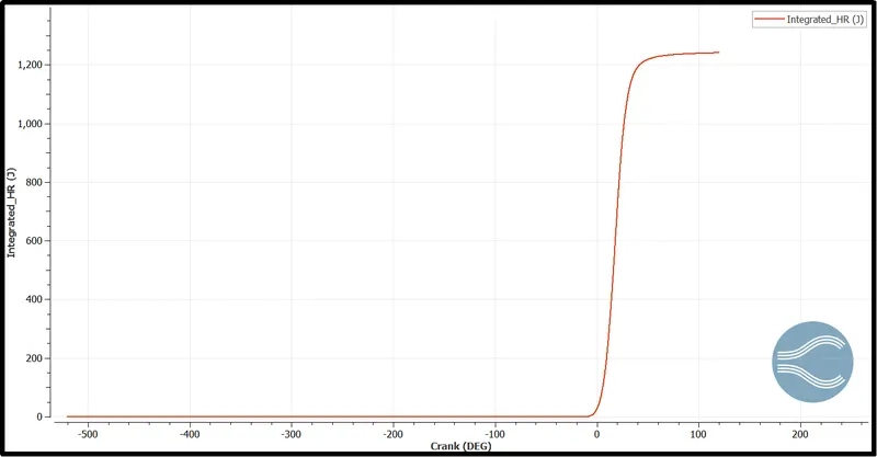
Integrated Heat Rate:-
The Combustion efficiency of this engine.
Combustion efficiency is a measure of how well the fuel being burned is being utilized in the combustion process. Complete combustion would result in 100 percent efficiency, but that is not possible in the real world because some losses are involved.
Max Integrated_HR = 1241.1646
Mass of fuel injected = 3e-05kg
Calorific Value of Iso-octain = 44 mJ/kg
`"Combustion Efficiency, "eta_c = ("Total Heat Release")/("Total Energy Count Of fuel")`
`"also "eta_c = ("Total Heat Release")/("m"xx"LCV of fuel")`
`:." "eta_c = 1241.1646/(3e^(-5)xx 44e^6`
`:." "eta_c = 94.0276 %`
The engine performance:-
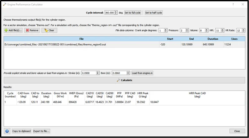
Work = 468.646 N-m
Duration = 240.199 deg
Rotation per minutes(rpm) = 3000
Rotation per seconds(rps) = 3000/60 = 50
Single rotation of piston = `360^o`
Rotation per second = 50 x 360 = 18000deg/sec
Time taken by the piston for complete rotation = 240.199/18000 = 0.01334sec
`"Power =" ("Work Done")/("Time taken")`
`"Power =" 468.646/0.01334 = 35130.885"W" or 35.13"KW"`
Torque:-
Torque is a twisting force that speaks to the engine’s rotational force and measures how much of that twisting force is available when an engine exerts itself.
`"Torque, " tau = ("power" xx 60)/(2 piN)`
`"Torque, " tau = (35130.885 xx60)/(2xxpixx 3000) = 111.83 " N-m"`
Significance of CA10, CA50, and CA90:-
With the variation in CA10, CA50, CA90 we can predict the combustion duration with manipulation of air-fuel ratios.
CA10:-
- CA10 is the crank angle corresponding to 10% of the cumulative heat release and it is widely considered as the start of combustion.
- the increase in the ratio of the fuel in the mixture markedly delayed the start of combustion.
- On the other hand, the start of combustion advanced with the increase of the equivalence ratio.
- Increasing the amount of fuel in the mixture causes the increase of the octane number of the mixture.
- Moreover, the heat capacity of the mixture decreased, and the mixture evaporated more slowly with the increase of fuel ratio in the mixture.
- The probability of the fuel molecules to match with the oxygen molecules increased as the amount of fuel in the mixture increased with the increase of equivalence ratio and therefore the combustion starts early.
CA50:-
- CA50 is the crank angle corresponding to 50% of the cumulative heat release and it is widely considered as the middle point of combustion.
- The CA50 was delayed with the increase of fuel ratio in the mixture.
- On the contrary, the CA50 advanced with the increase of the equivalence ratio.
- The fact that the CA50 occurs before the top dead center (TDC) causes a negative work on the piston, causing a decrease in thermal efficiency.
CA90:-
- CA90 is the crank angle corresponding to 90% of the cumulative heat release and it is widely considered as the end of combustion.
- The CA90 was delayed with the increase of fuel ratio in the mixture and it advances with the increase of equivalence ratio.
- CA10 and CA50 delayed with the increase of fuel ratio in the mixture also led to the delay of CA90.
- Similarly, CA10 and CA50 advanced with the increase of equivalence ratio also led to the advance of CA90.
- The combustion duration was calculated by the difference between CA90 and CA10.
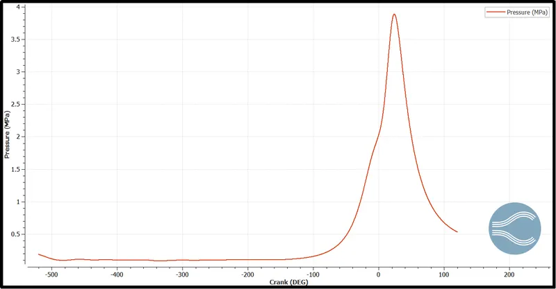
Pressure Variation with the crank angel:-
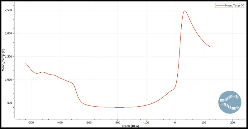
Mean Temperature Variation with the crank angel:-
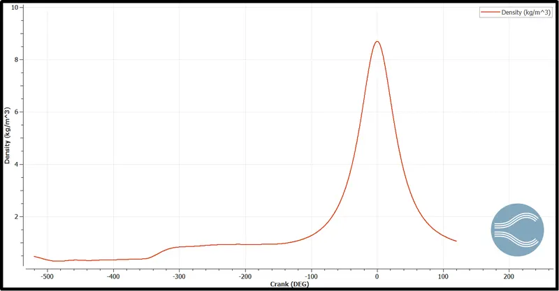
Density variation with crank angle:-
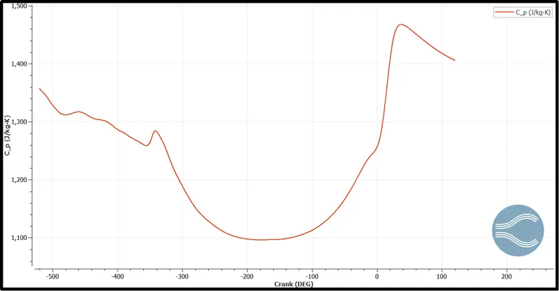
Cp variation with crank angle:-
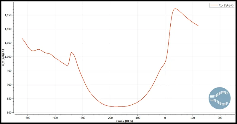
Cv variation with crank angle:-
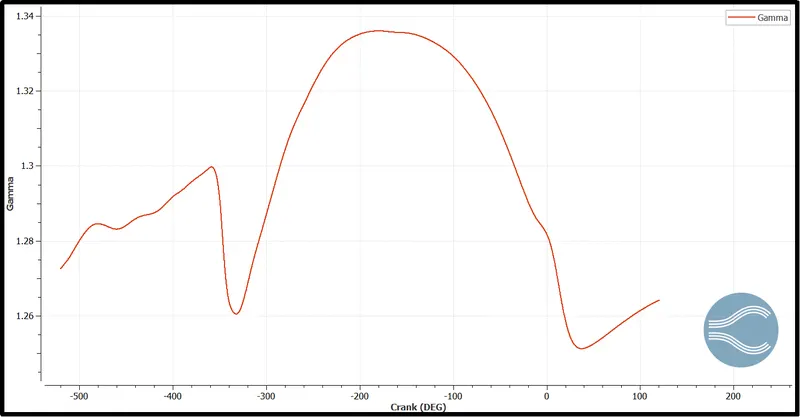
Gamma variation with crank angle:-
In the theoretical calculation, we consider the constant value for gamma as 1.4. But it changes as a function of the crank angle.
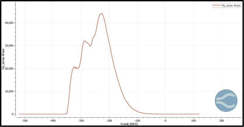
Liquid Spray Drops in the cylinder:-
Using this plot, one can evaluate the Lagrangian parcels that are active in the domain. At the end of the combustion, there is no fuel left in the engine which means complete combustion had been taken place.
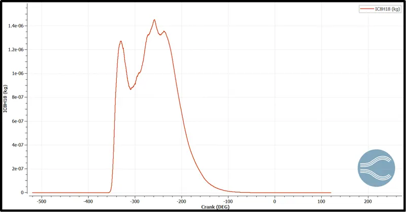
The amount of fuel varies in the cylinder with crank angle:-
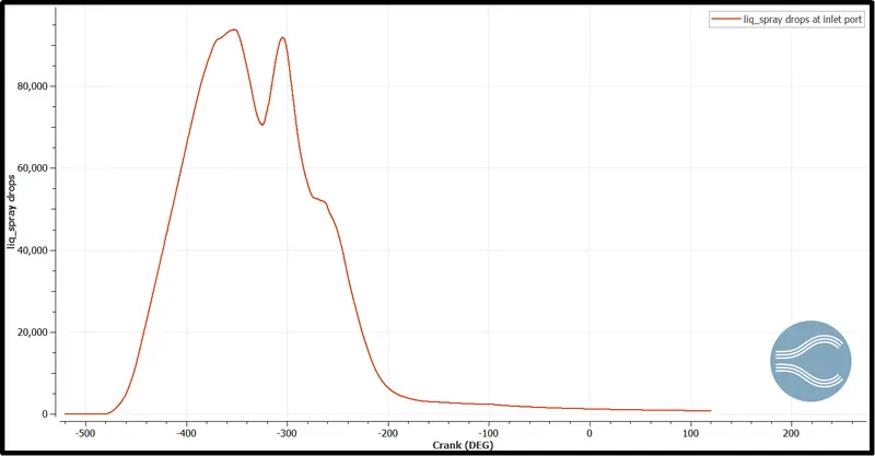
Liquid spray drops variation in intake port:-
A small amount of fuel always stays inside the intake port after each spray.
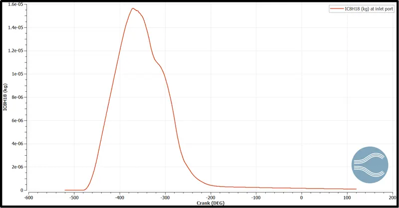
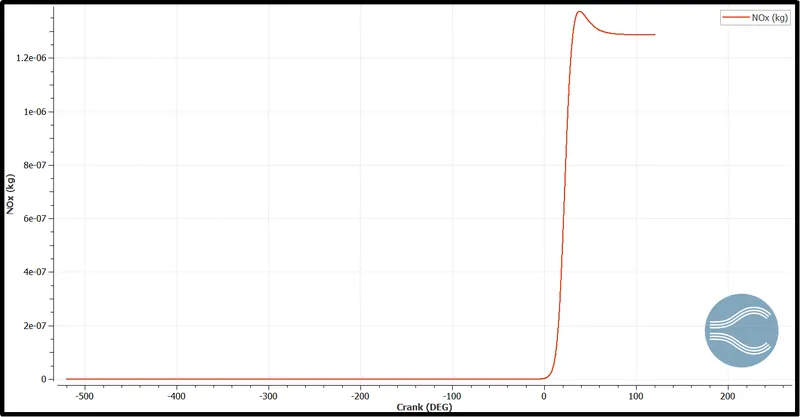
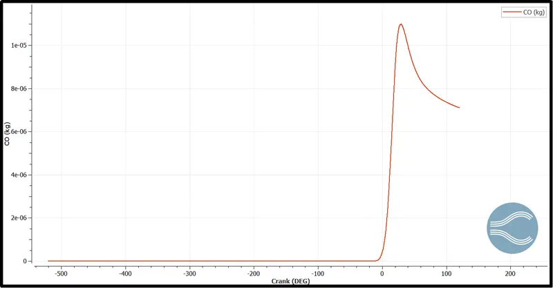
Emission Plots (Soot, NOx, CO)
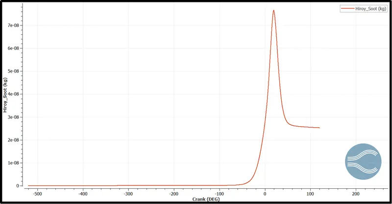
Temperature Variation and spark ignition Animation:-
Temperature Variatio animation with valve movement:-
Velocity variation animation:-
Conclusion:-
- In this simulation RANS K-epsilon model was used to simulate to capture the turbulence with coarser grids and larger time steps. which provide results with approximation but on the other hand save a lot of computation power and time.
- Liquid Fuel drops stick to the surface at the intake port so to get accurate fuel spray calculation we need to run the simulation for at least 10 cycles. Then we can calculate the actual flue supply required for the combustion.
- This simulation does not provide the information for wall heat transfer as we did not consider the solid part of the IC engine components. To get is one need to perform CHT simulation.
- With the integrated Heat rate parameters, we can calculate the combustion efficiency of the IC engine.
- At last, CONVERGE provide the engine performance calculator by using those parameters we can calculate the value for Engine Torque.
- CA10, CA50, and CA90 denote the crank angle corresponding to 10%, 50%, and 90% cumulative heat release respectively. where CA10 is considered at the start of the combustion, CA50 is considered as the middle point of combustion and finally, CA90 is considered as the end of combustion.
References:-
[1] Principles of Heat Transfer in Internal Combustion Engines from a Modeling standpoint - http://www.tfd.chalmers.se/~lada/postscript_files/mirko-phd.pdf
[2] PREDICTIVE FLUID-SOLID HEAT TRANSFER - https://convergecfd.com/benefits/conjugate-heat-transfer
[3] What is Torque? - https://www.toyota.ca/toyota/en/connect/3843/what-is-torque-in-cars