Project 1 - Surface preparation and Boundary Flagging (PFI)
Surface preparation and Boundary Flagging (PFI)
Aim:-
- Perform geometry diagnosis and repair the model.
- Perform boundary flagging operation.
- Assign the boundary condition in the surface preparation task.
Objective:-
- Import the IC Engine Geometry model in the CONVERGE.
- Run the geometry diagnostic command and perform geometry cleanup.
- Define the boundary for each wall of the geometry.
- Setup the simulation setup using the NoHydro simulation type.
- Assign the boundary conditions to each boundary.
- Provide various regions and meshing parameters.
- Export the data file and simulate the setup using any text editor.
- Open the 3D output data in ParaView and create a slice over a different location to show generated mesh.
- Create animations showing the mesh movement and valve working.
Import Geometry:-
Import the IC engine geometry into converge.
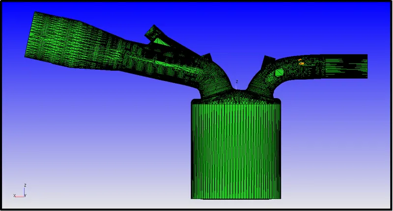
Geometry Diagnosis:-
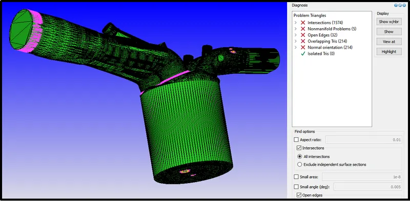
Run the geometry diagnosis to find out the problems in geometry. Here we can see the problems in the intersections, Open Edges, overlapping tris, and normal orientations.
Geometry Cleanup:-
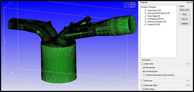
Using the geometry cleanup methods like patch, delete, and create option we geometry was cleaned up.
Boundary Definition or Boundary Flagging:-
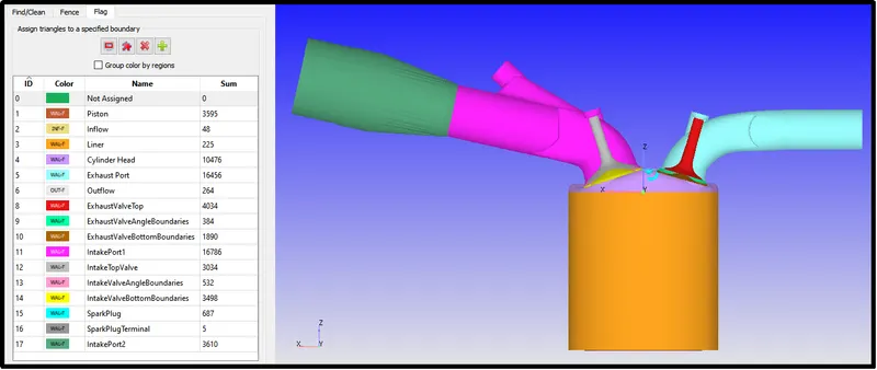
The separate boundary was assigned to each surface considering its working and temperatures.
Simulation Case setup:-
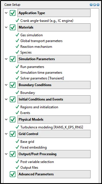
The following is the setup tree for the No hydrodynamic simulation case.
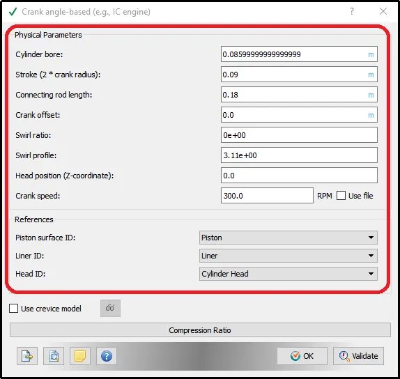
IC engine specifications:-
Specify the Engine Parameters in the below window.
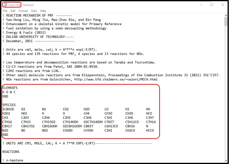
Species Definition:-
Feed the mech.dat file data in a Reaction mechanism setup
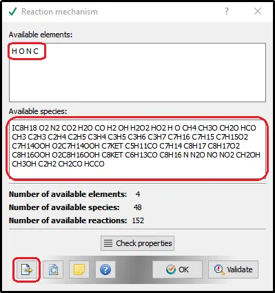
The Reaction mechanism setup reads all the species data from the mech.dat file and shows it in the available species box.
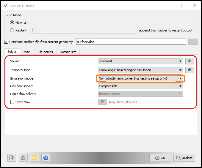
Run Parameters (No hydrodynamic setup):-
In this project, we only check the mesh generation and valve timing, therefore, we are selecting no hydro simulation for this particular simulation.
Simulation time parameters:-
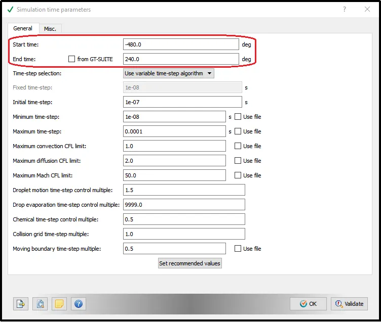
In the Simulation time parameters setup, we define the start crank angle and end crank angle.
Boundary Conditions:-
Now, the boundary condition was provided to all the wall and inlet-outlet boundaries.
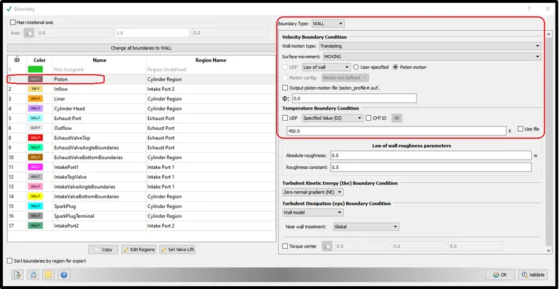
Piston Wall:-
The piston is the moving element in the cylinder. It reciprocates inside the engine cylinder. Therefore, the moving wall boundary is assigned to it by considering 450K temperature.
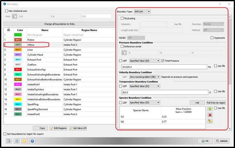
Inflow:-
For the inflow boundary condition, we define the atmospheric pressure which is 101325 in Pa with a temperature of 363k. and it will be an air inlet.
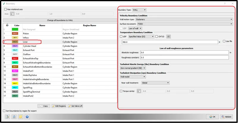
Cylinder Liner wall:-
The cylinder is the stationary component so the wall is defined as stationary with temperature 450.
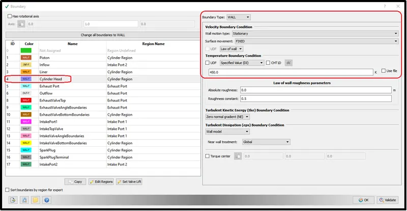
Cylinder Head:-
The same condition as the cylinder wall was provided to the cylinder head.
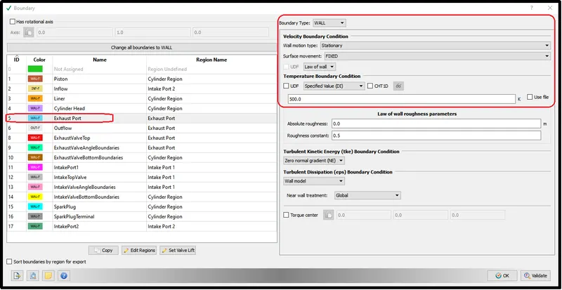
Exhaust port Wall:-
The exhaust port also always stayed stationary so define it as a stationary wall.
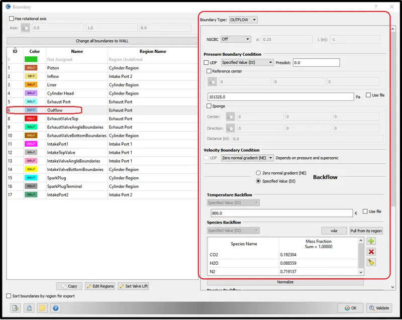
Outflow condition:-
The initial outflow conditions will be atmospheric with the different species.
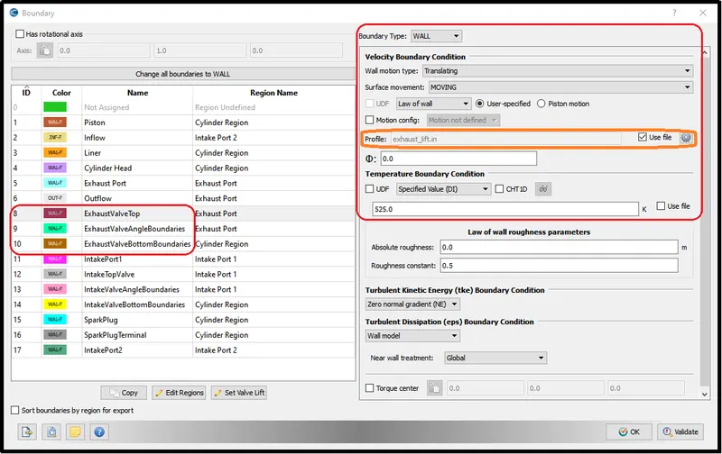
Exhaust Walls:-
Use the exhaust_lift.in the file to define the exhaust valve motion.
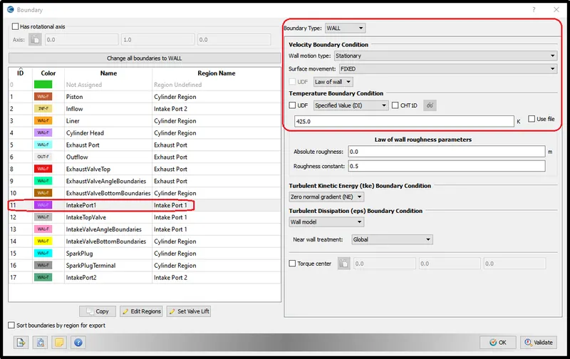
Intake Port wall:-
The intake port wall will remain stationary so define it as a stationary wall.
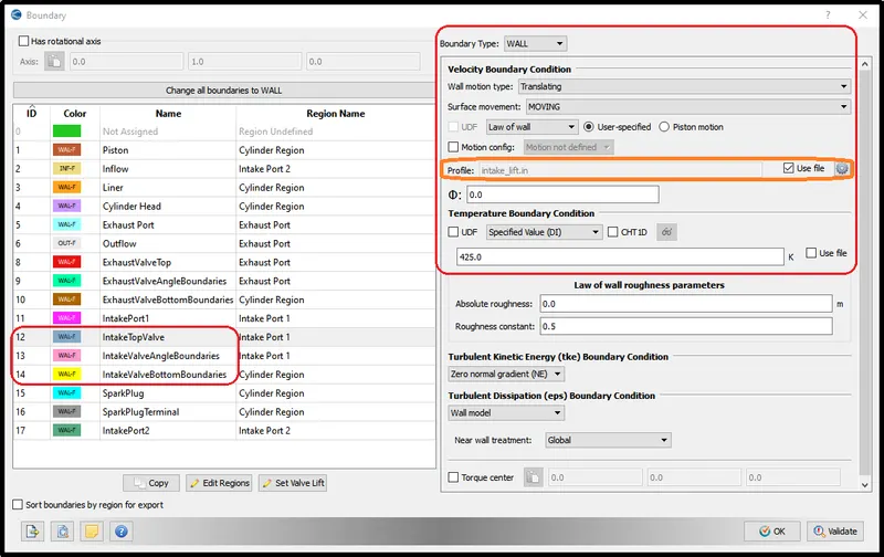
Intake valve walls:-
Use intake_lift file to provide intake valve motion.
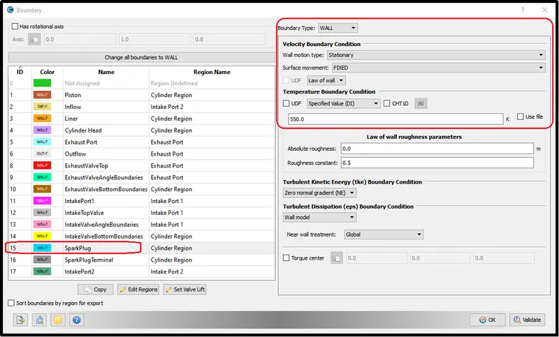
Spark Plug wall:-
A spark plug wall is also defined as a stationary wall with a 550K temperature.
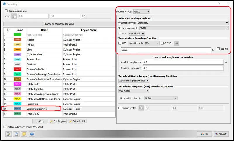
Spark Plug terminal Wall:-
Spark plug terminal temperature provided a little higher than the remaining wall components.
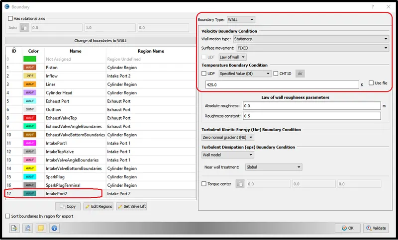
Intake Port2 wall:-
For the intake port2, the wall condition is set to be stationary.
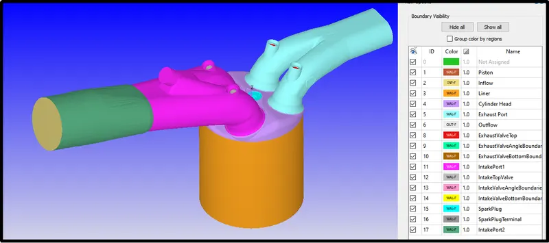
Assigned boundaries to various surfaces:-
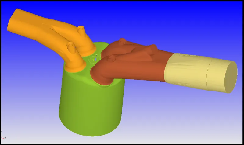
After assigning all the boundary the geometry will look like this-
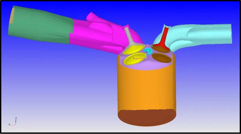
Cut section view of the geometry.
Regions Definition and Initialization:-
In the region, define different regions in the geometry.
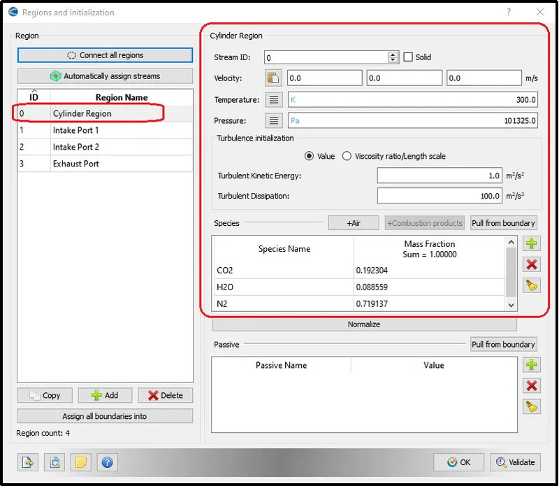
Cylinder Region:-
The In-cylinder region provides the species.
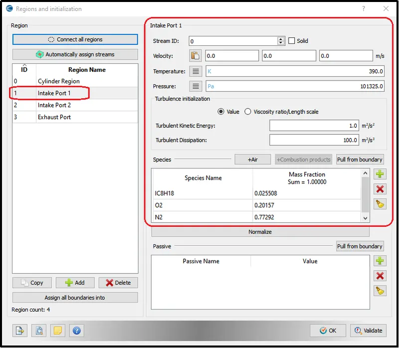
Intake Port1 Region:-
In the intake port1 region, specify the fuel species element at the inlet.
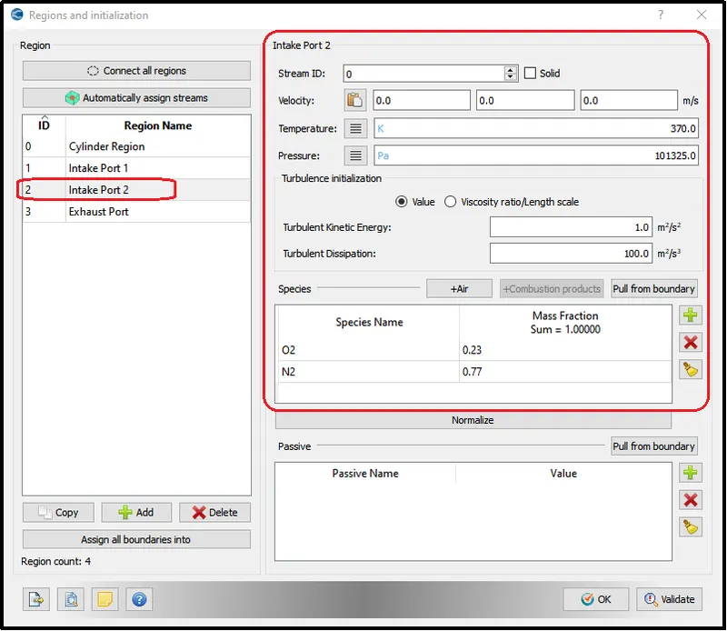
Intake Port2 Region:-
In the intake port2 region, specify provide the air species.
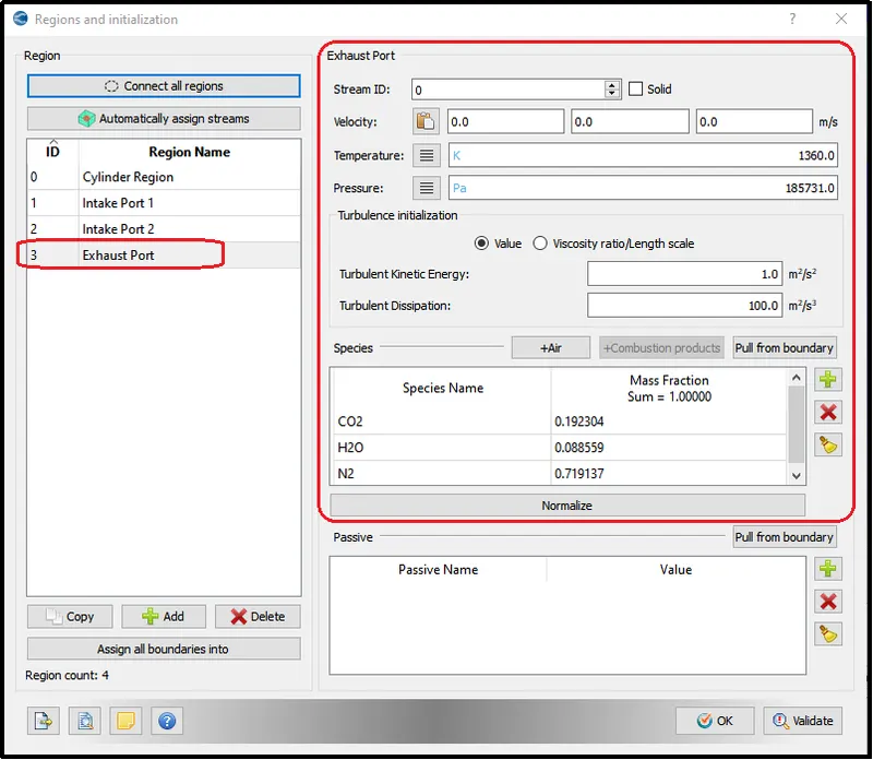
Exhaust Port Region:-
Finally, provide the exhaust species.
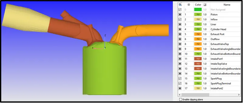
Regions visualization after region assignment:-
Cut-Section of the geometry.
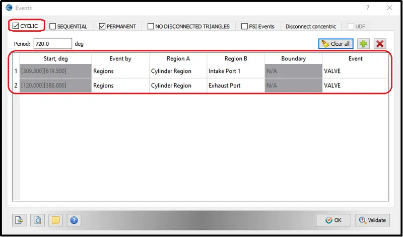
Events Definition for Intake and Exhaust port:-
provide the event definition between each region according to valve time or movement.
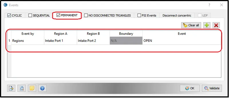
Event definition between region Intake port1 and Intake port2 will always be open so define it in the permanent section.
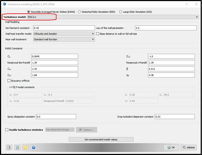
Turbulence Model:-
Here define RNG k-e as a turbulence model.
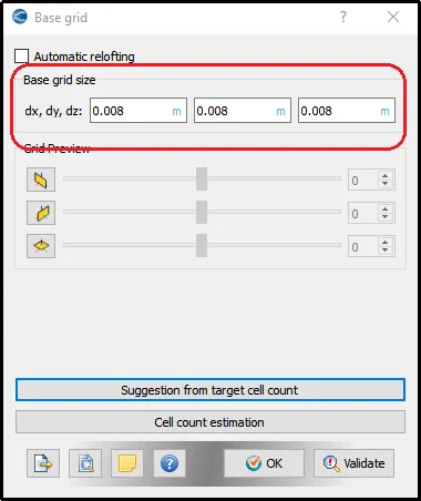
Base Grid:-
Fixed embedding:-
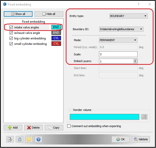
To refine the mesh near the walls and different regions we will provide the Fixed embedding.
At Intake valve angle wall:-
Refine the mesh near the contact wall surface area of the intake wall.
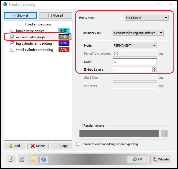
At Exhaust valve angle wall:-
Refine the mesh near the contact wall surface area of the exhaust wall.
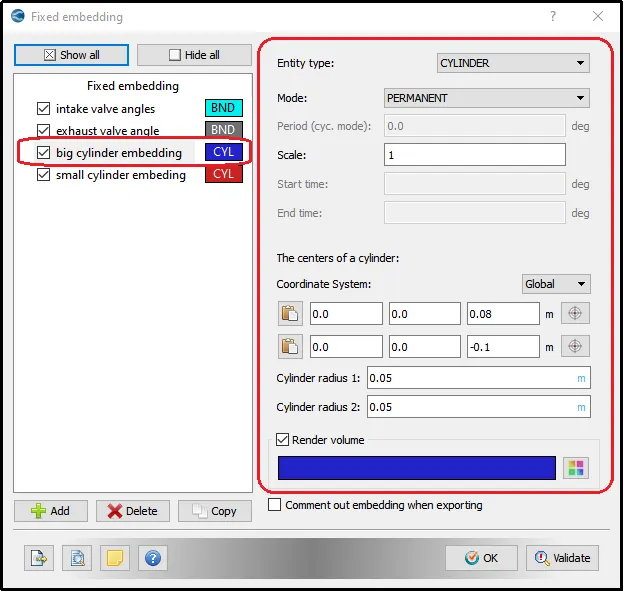
For large Cylindrical volume:-
refine mesh near the cylinder and valve moment area.
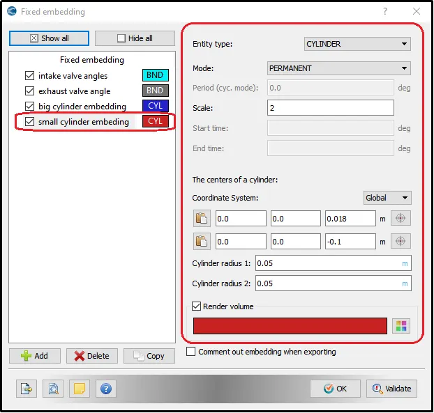
For Small Cylindrical Volume:-
refined mesh near the cylinder region.
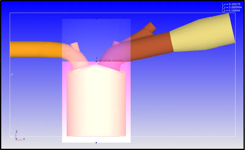
Large and Small cylindrical Embedding:-
After defining the cylindrical embedding the converge will show the presentation exhibited in the following picture.
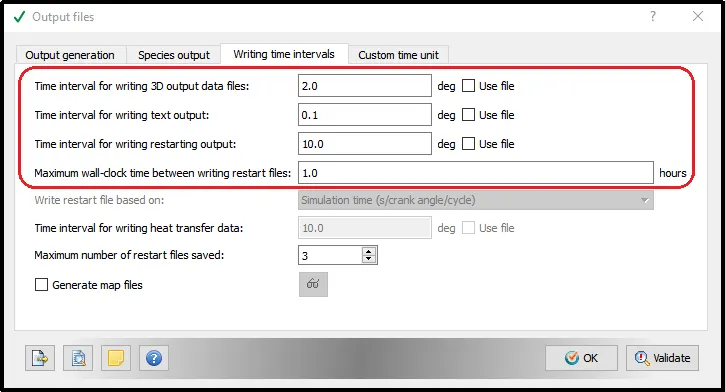
Output files parameters:-
The 3D output file will be generated after every 2 degrees of rotation of the crankshaft.
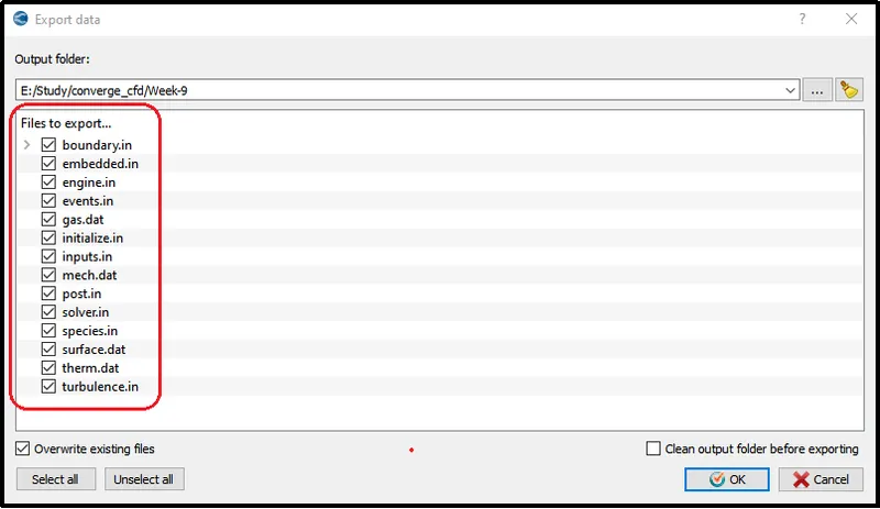
Export File:-
Export the input setup files to run the simulation.
Errors Faced during the simulation.
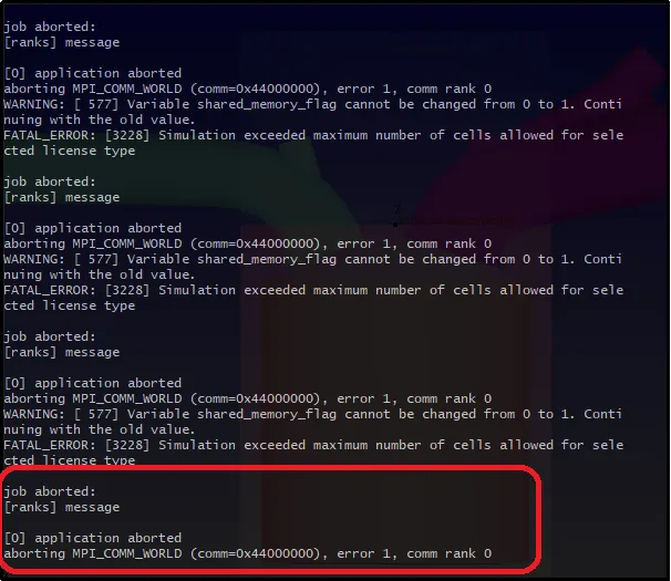
License Error:-
The license error occur while simulating the results because of the mesh cell number exceeded the minimum allowed limit by the converge.
Error Handling:-
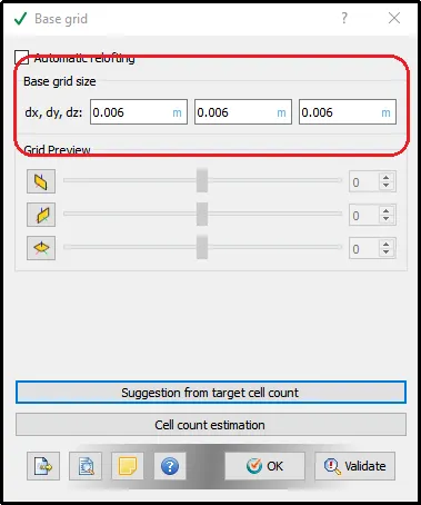
To minimize the number of grids below the allowable cells number by CONVERGE, the grid size was increased by 0.002m.
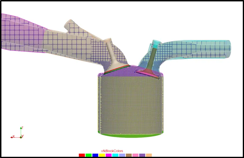
Mesh Animation
Final animation generated by the above mesh setup.
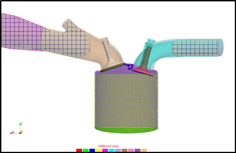
Geometry and Mesh animation:-
Geometry animation without mesh:-
Conclusion:-
- The simulation was set up to check the valve movement and mesh generation in IC Engine Geometry.
- No hydrodynamic simulation setup is always vital to verify the simulation setup is good or bad.