FULL HYDRO case set up (PFI)
AIM: To set up the Full Hydro simulation case for SI8-PFI Engine model, to find the compression ratio, combustion efficiency, power and torque for this engine and to explain the significance of ca10, ca50 and ca90
Theoritical Background:
Port Fuel Injection
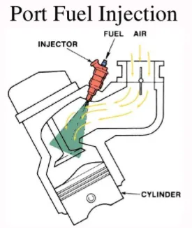
Port Fuel injection is when fuel is injected prior to the valve and cylinder, where the combustion happens. The intake valve will have a fuel injection system that sprays fuel into the air coming into the engine. The fuel injector in the PFI engine are mounted on the intake manifold. Air and fuel mixture are pulled in to the cylinder head as the intake valve opens
Spray Modelling
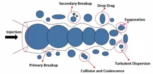
The approximate method to calculate the spray motion and its relevant parameters is called as Spray modelling. Converge can model both gaseous and liquid sprays. Converge includes state of art model for spray processes including liquid atomization, drop breakup, collision, turbulent dispersion and drop evaporation.
Spraying the fuel from intake port to inside the cylinder is done in every cycle during the operation of port fuel injection engine. The fuel sprays can be completely simulated by using CFD multiphase simulations, but this results in simulation running for a very long time. This can be prevented by statistically modelling the same effect of spray instead of actually simulating it.
Spray Modeling Techniques
1] Gaseous Spray: Converge uses Eulerian solver, which sets the species mass fractions and mass flow rate at the Inflow boundary
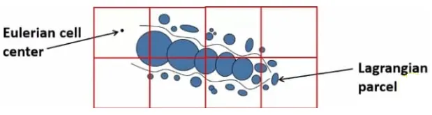
2] Liquid Spray: Converge uses Lagrangian solver to model the descrete parcels and Eulerian solver to model the continuous fluid domain. Heat, Momentum and mass transfer occur between discrete and continuous phases through source terms in transport equations.
Parcels
Converge introduces parcels(collections of drops) in to the domain at the injector. Each parcel represents a group of identical drops (same radius, velocity, temperature etc). Converge solves for radius, velocity etc on per parcel basis rather than a per-drop basis, because the drops in the parcel are identical. The parcels statistically represents the entire spray field.
Parcel undergoes following physical processes
1] Primary breakup - Splitting up of drop from mainstream
2] Secondary breakup - Splitting up of primary drop in to multiple drops
3] Drop Drag - Drag caused by air on moving drop
4] Collision and Coalescence - Collision of 2 or more drops and formation of new drop
5] Turbulent dispersion - Transport of mass, heat or momentum within a system due to random and chaotic time dependent motions
6] Evaporation - Evaporation of small liquid drops in to vapour
Setup: Parcel Distribution
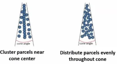
For solid cone spray, converge assumes injection is conical, We have to select the even distribution of parcel throughout the cone option
Case Setup:
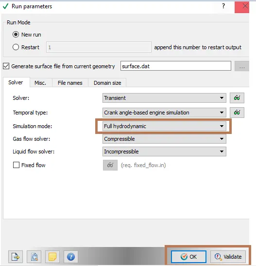
We are setting up a Full Hydro simulation case by using the No hydro setup
Engine Geometric Parameters
- Bore =0.086 m
- Stroke = 0.09 m
- Connecting rod length = 0.18 m
- RPM = 3000
1] Materials
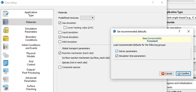
Enable the parcel simulation and confirm the permission to load the recommended defaults for the solver and simulation time parameters
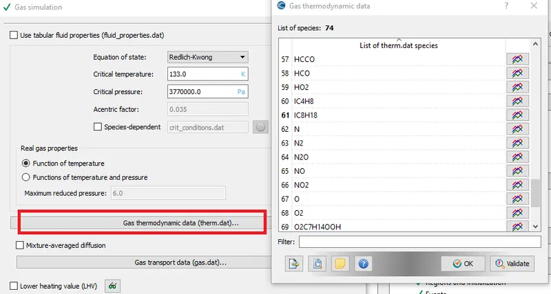
a) Gas Simulation: Use Gas Thermodynamic data, this gives thermodynamic properties of each gas species
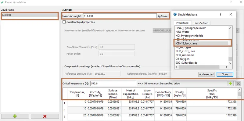
b) Parcel Simulation
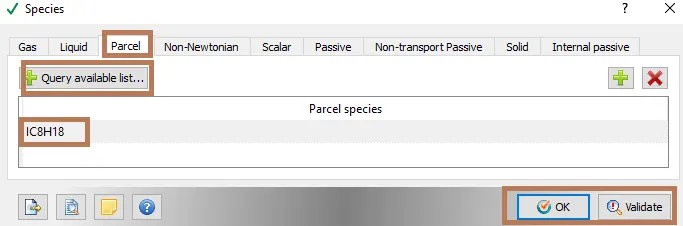
IC8H18 is used as fuel in this simulation because it has properties very similar to gasoline fuel. It is used in large proportions to increase the knock resistance of the fuel. It specifies the fuel being used.
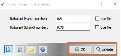
c) Global Transport Parameters
Keeping the default values for Global transport properties
d) Reaction Mechanism
Import mech.dat file. This takes care of Gas phase simulation
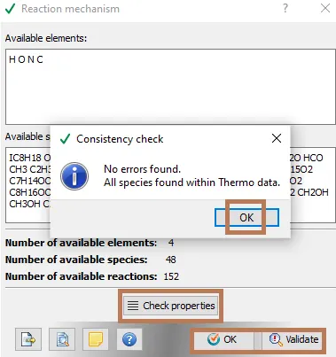
e) Species: We need to add participating species parcel i.e IC8H18
2] Simulation parameters
a) Run Parameters
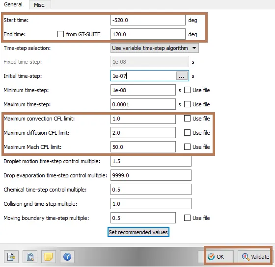
b) Simulation Time Parameters
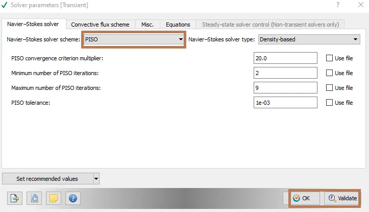
c) Solver Parameters
4] Boundary Conditions
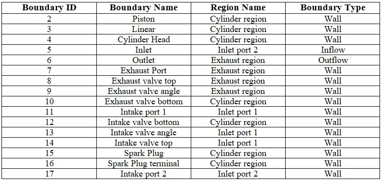
We have to assign boundary conditions for different faces of Geometry as shown in the table below
5] Regions and Initialization
4 regions are defined
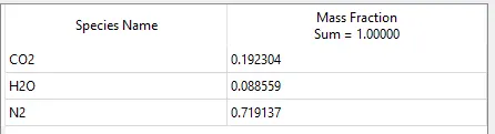
a) Cylinder region ,
velocity = [0,0,0] m/s, Stream ID = 0, Temperature = 300 K, Pressure = 101325 Pa
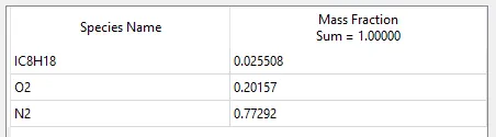
b) Intake Port 1 region
velocity = [0,0,0] m/s, Stream ID = 0, Temperature = 390 K, Pressure = 101325 Pa
c) Intake Port 2 region
velocity = [0,0,0] m/s, Stream ID = 0, Temperature = 370 K, Pressure = 101325 Pa
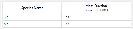
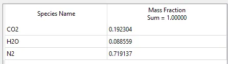
d) Exhaust region
velocity = [0,0,0] m/s, Stream ID = 0, Temperature = 1360 K, Pressure = 185731 Pa
6] Events
We have to provide events when we have multiple events
a) Cyclic Events
Cyclic event is created between Cylinder region and Intake Port 1 region and also between Cylinder region and Exhaust region. The event follows the valve lift profile and according to that converge enables or disables the disconnected triangle to regulate the fluid flow.

b) Permanent Events
The intake port is split is 2 boundaries and 2 regions but there is a permanent open event between intake port 1 and intake port 2

7] Physical Modeling
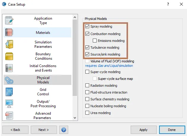
Enable Spray modeling, Combustion modeling, Turbulence modeling and Source/Sink modeling
A) Spray Modeling
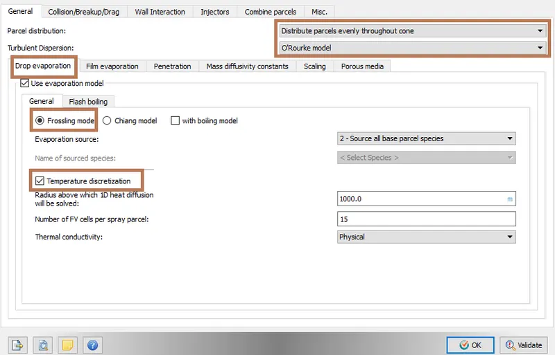
Penetration - Converge writes the Liquid and Vapour penetration length at each output interval, It calculates the vapour penetration length for each interval
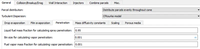
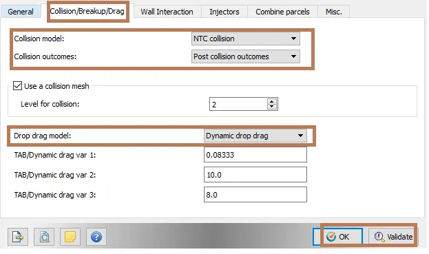
Drop Drag - When Parcles entering through the gas phase it encounters air resistance. Collision calculation is based upon if one parcle is going to hit another parcel or not. To perform collision calculations we need another mesh which is different from original mesh provided, which is called as Collision Mesh. Simulation with collision mesh can much more accurately represent the spray dispersion eliminating the grid effects.
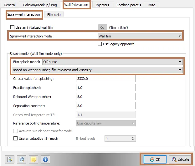
Wall Interaction: When a drop parcel coule collide with the wall, it could rebound back, escape or remain on the wall creating a film, these effects are modeled using O' Rourke model
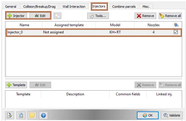
Injectors
One Injector can have multiple nozzle and here we are using 4 nozzle for single injector
Injected species/ Rate-shape
Add parcel species IC8H18 with mass fraction of 1
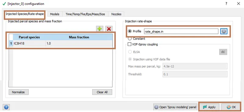
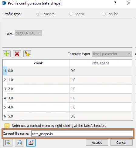
Profile of rate vs Crank is as determined below

Models:
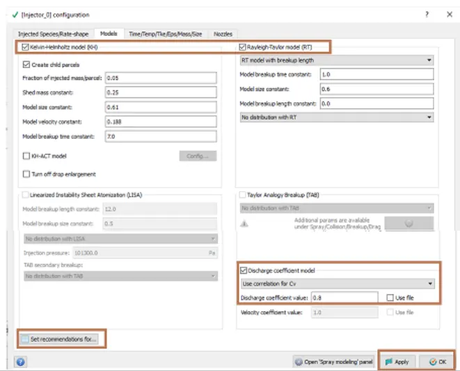
Enable the Kelvin-Helmontz model and Rayleigh-Taylor model with default values. Both these models are used for Solid cone sprays irrespective of the fuel.
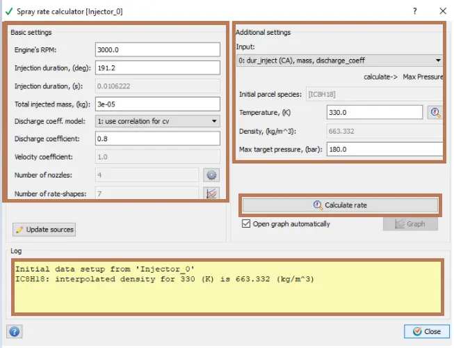
Discharge coefficient model is enabled with discharge coefficient value of 0.8. Set recommendations for Gasoline PFI
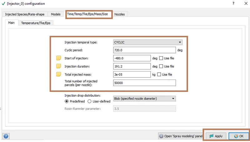
Injection Parameters
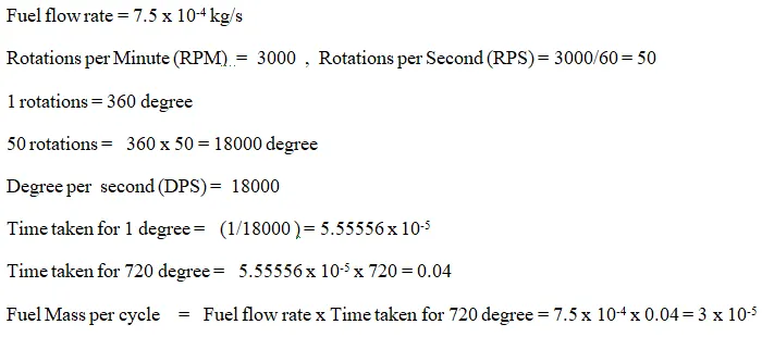
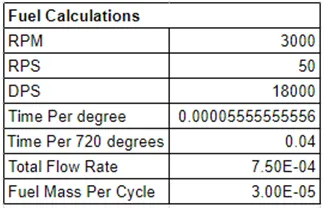
- Fuel flow rate = 7.5e-4 Kg/second
- Injection start time = -480.0
- Injection duration = 191.2
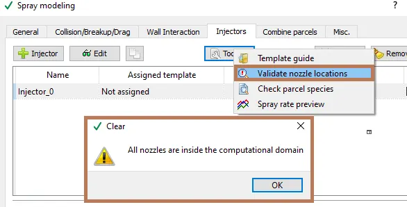
- Fuel temperature = 330K
Total injected mass per cycle is calculated as below
Nozzle
Using + Add nozzle 3 more nozzles are added
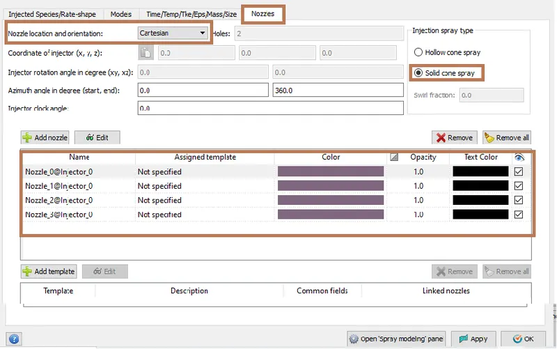
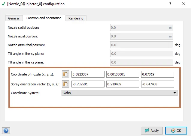
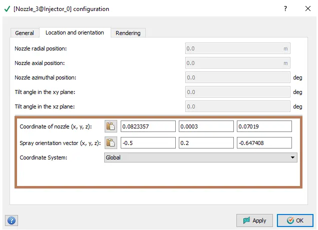
The configuration of all the 4 nozzles are as shown below
a) Nozzle 0
- center 0.0823357, 0.00100001, 0.07019
- Align Vector -0.732501, 0.210489, -0.647408
b) Nozzle 1
- center 0.0823357, -0.00099999, 0.07019
- Align Vector -0.732501, -0.210489, -0.647408
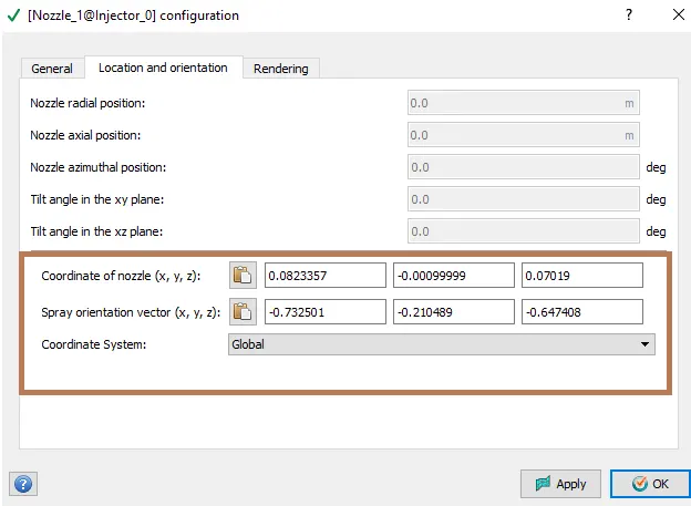
c) Nozzle 2
- center 0.0823357, -0.0004, 0.07019
- Align Vector -0.5, -0.2, -0.647408
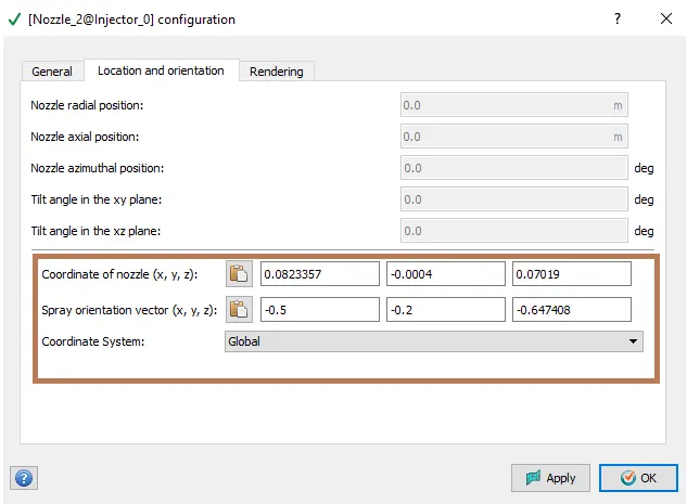
d) Nozzle 3
- center 0.0823357, 0.0003, 0.07019
- Align Vector -0.5, 0.2, -0.647408
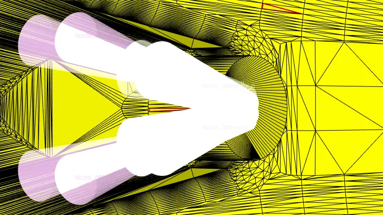
Nozzle orientation

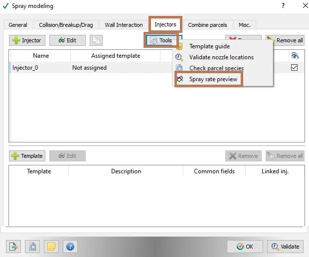
Spray rate Preview
Spray rate Calculator
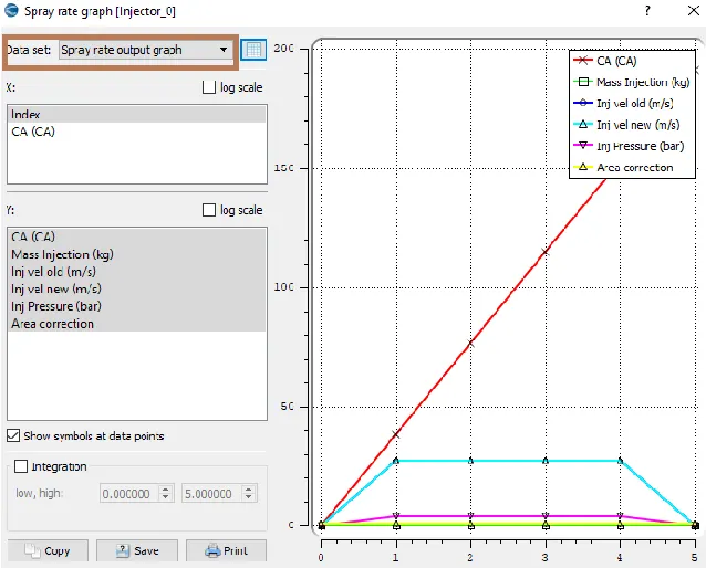
Spray rate Graph
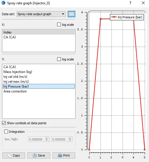
Injector Pressure(bar)
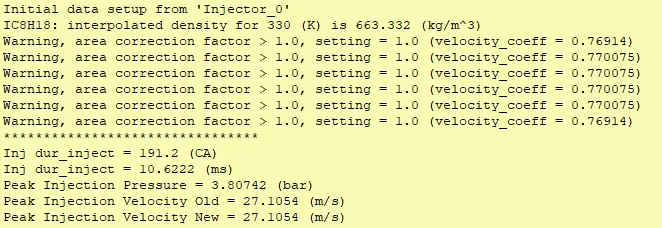
Validating nozzle locations
B) Combustion Modeling
Combustion modeling facilitates energy transfer in engine. Converge software contains detailed chemistry solver and simplified combustion models.
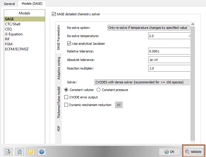
SAGE detailed chemisty solver - It is the most predictive and accurate way to solve the model combustion. It accurately models ignition and laminar flame propogation. It solves detailed chemical kinetics during combustion and determines kinetically limited phenomenon such as engine knocks and emissions. It reads in a reaction mechanism in CHEMKIN format and solves Ordinary Differential Equations to find the reaction rates. It parallelizes independently of the flow solver. It couples with transport solver through source terms in the species transport equations.
General

SAGE Parameters
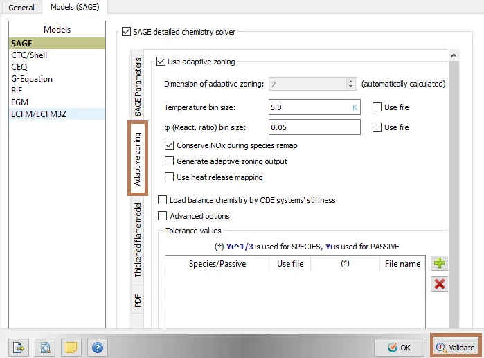
Adaptive Zoning
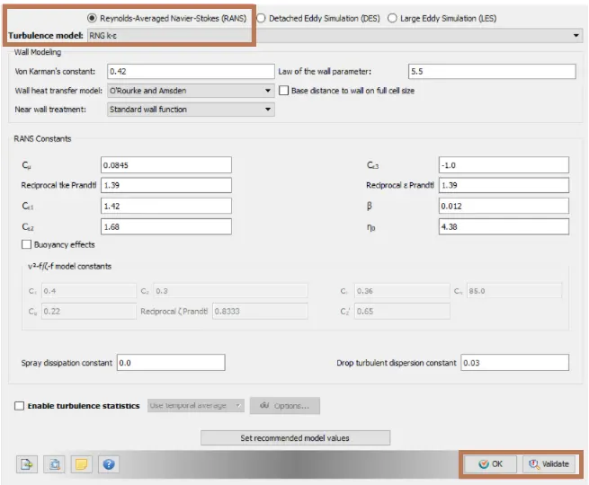
Turbulance Modeling
Set the turbulance model as RNG k-epsilon
Source/ Sink Modeling
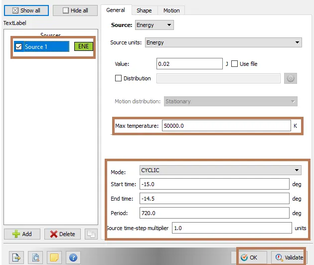
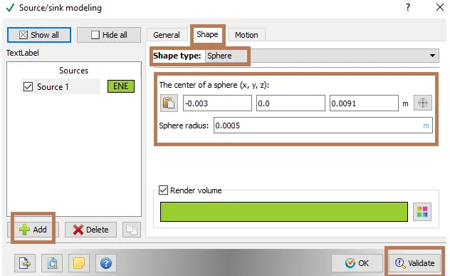
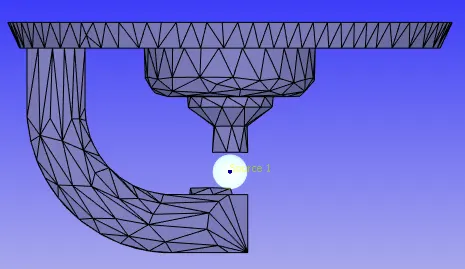
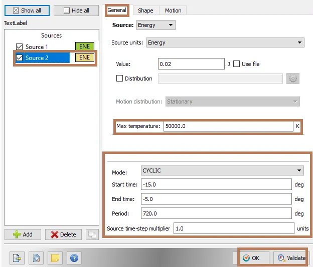
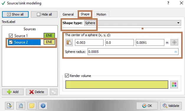
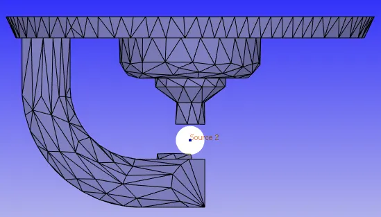
The energy from the spark plug is going to be sourced through energy equation which inturn is going to increase the temprature of the species. This temprature is going to be introduced in the species transport equation. There is a source term in the species transport equation which is responsible for combustion to occur which in turn affects the chemical kinetics. This will cause new products to release heat.
Source 1:
General
Shape
Source 2
General
Shape
Grid Control
Enable Adaptive mesh refinement and Fixed Embedding
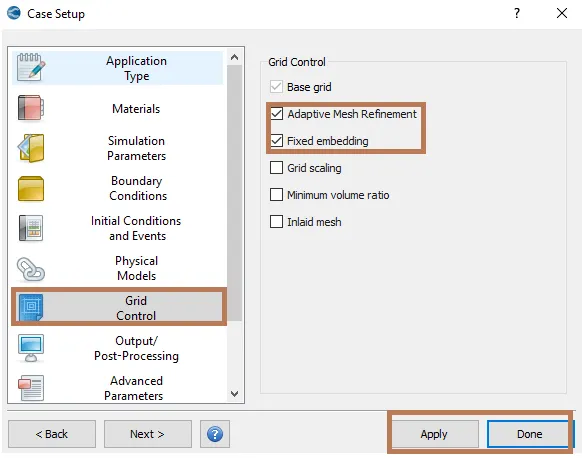
Base Grid
base grid size = 4mm
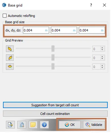
Adaptive Mesh Refinement
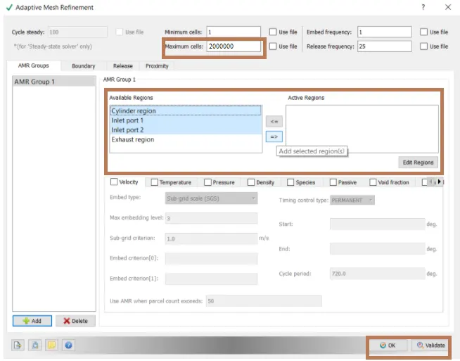
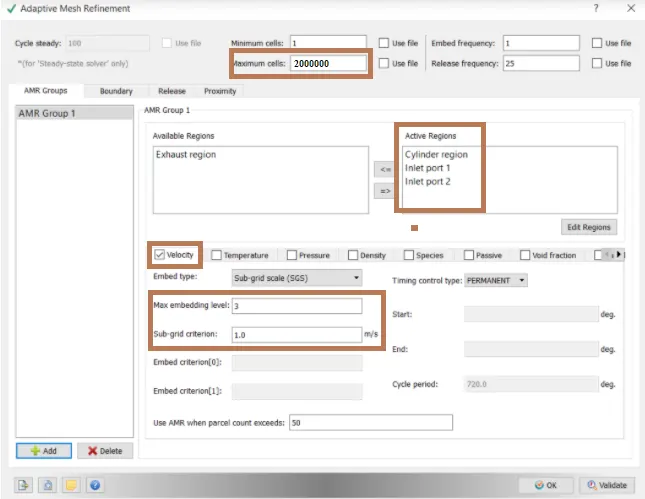
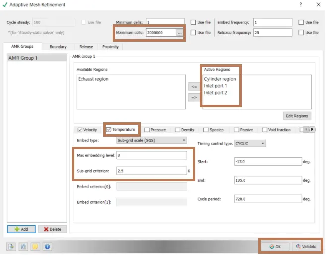
Fixed Embedding
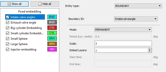
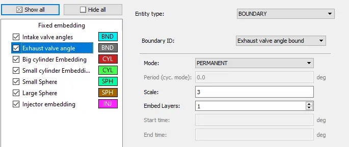
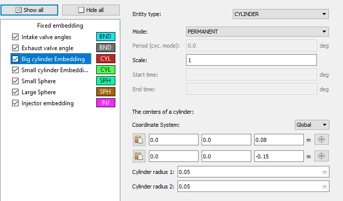
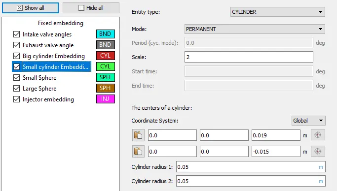
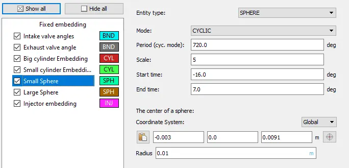
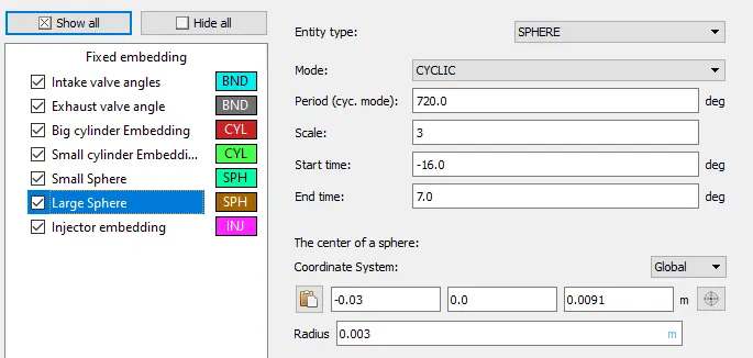
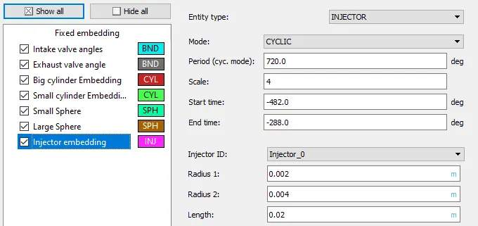
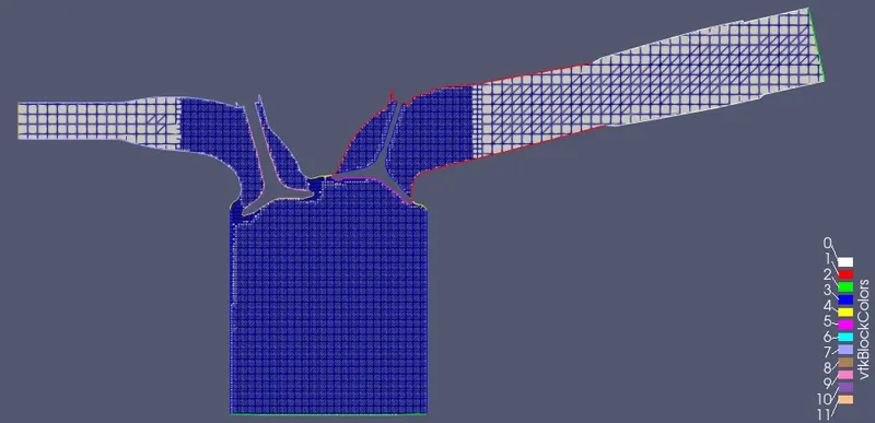
Fixed embedding is provided near valve angles as the space between valve angle and valve seat is very small and the base grid with 4mm grid size will not give accurate results. Fixed embedding is provided to refine the specific areas and capture the combustion details and calculate them properly. Cylindrical type embedding is provided on the cylinder to make them finer as compared to base grid.
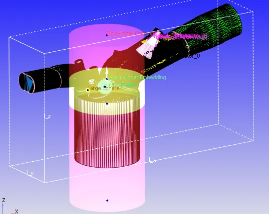
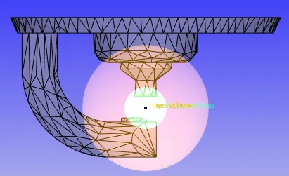
Intakevalve angle
Exhaust valve angle
Big Cylinder Embedding
Small Cylinder Embedding
Small Sphere
Large Sphere
Injector Embedding
compression ratio of this engine
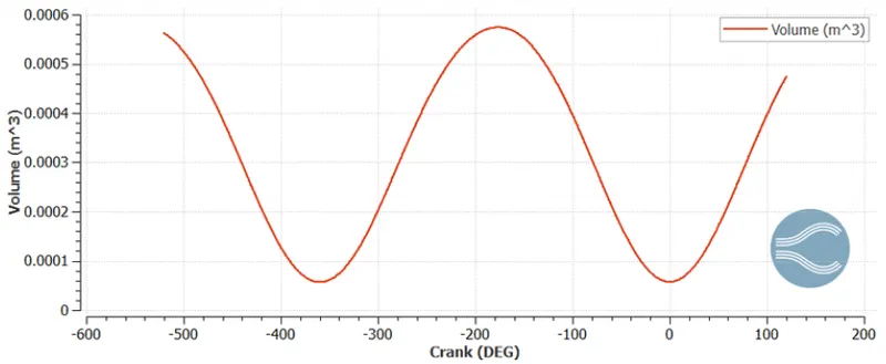
The ratio of Maximum volume to the Minimum volume in the cylinder of the Internal combustion engine is the Compression ratio. The Crest and the Trough indicates the four storkes of Port Fuel Injection Engine.
At the beginning of the Intake stroke the air volume inside the cylinder is more which means the piston is at the Bottom Dead Centre(BDC) and the crank angle is -520 degree. .During the Compression stroke the piston moves towards the Top Dead Centre(TDC) as a result of which the air volume inside the cylinder reduces. At TDC the compression stroke is completed and the fuel injection takes place as a result of which ignition happens, combustion occurs. The piston is now pushed towards the Bottom Dead Centre(BDC) and the volume inside the cylinder increases during the power stroke. Now the Combustion gases are sent out of the exhaust valve and again Piston moves upwards during the exhaust stroke reducing the volume inside the cylinder.

Why do we need a wall heat transfer model? Why can't we predict the wall temperature from the CFD simulation?
Some part of the heat due to combustion is released from the cylinder walls. When more than one heat transfer modes are considered with the solid bodies it is said to be Conjugate Heat Transfer(CHT) simulation. Simulating the IC engine flow along with the CHT simulation will increase the computational time. So instead of simulating the heat transfer through walls it is modeled using models like O'Rourke model. In the present simulation O'Rourke model is used as the wall heat transfer model. This model only captures only wall heat transfer or CHT simulation and not CFD simulation, hence we require a wall heat transfer model.
CFD simulation involves solving Navier-stokes equation which involves lot of computational time and power. The physical models used in the CFD simulation uses some approximation to reduce the computational time. Wall heat transfer model is mainly focussed on solving heat transfer equations giving less importance to fluid motions and reactions.
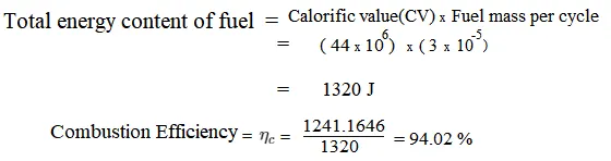
Calculating the combustion efficiency of this engine
Not all the fuel supplied to the engine cylinder undergoes combustion. For comustion to occur there must be enough supply of oxygen. There are several factors which influences the combustion which are the air-fuel intake the size of the droplets. As there is some physical losses the total amount of fuel sprayed by the ports are not converted in to exhaust gases during the combustion.
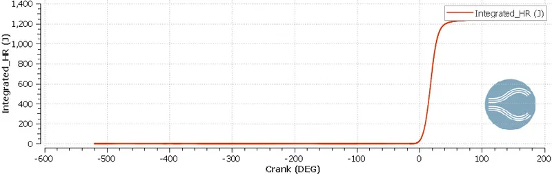
The Combustion Efficiency is defined as a measure of how effectively the heat content of a fuel is transferred into usable heat. that is how well the equipment is burning a specific fuel.

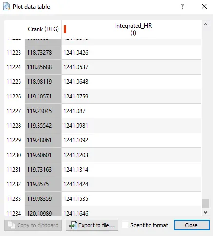
The total amount of heat released during the combustion = 1241.1646 J
The fuel used here is gasoline having the calorific value 44MJ
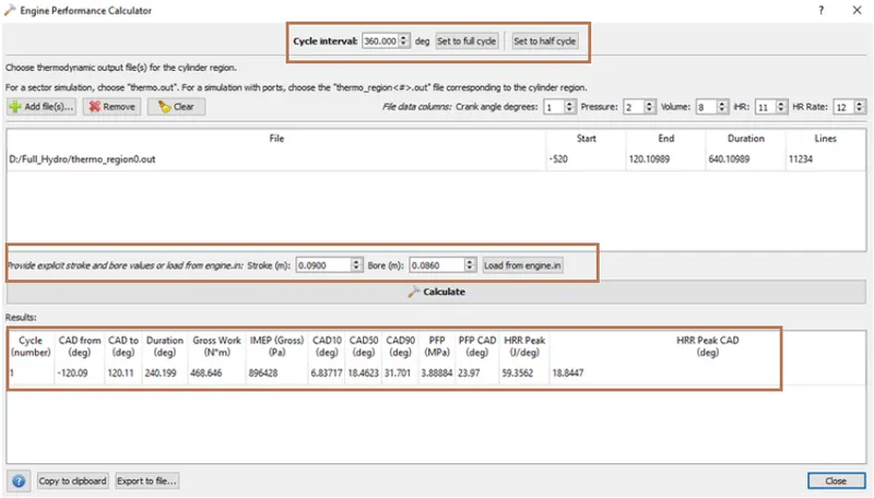
using the engine performance calculator, to determine the power and torque for this engine.
Engine Geometric parameters
- Bore =0.086 m
- Stroke = 0.09 m
- Connecting rod length = 0.18 m
- RPM = 3000
The engine performance calculator is used to analyse the physical data and get useful results from data
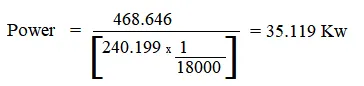
Power = Work Done /Time taken
Rotation per minute(RPM) = 3000
Rotation per Second(RPS) = 3000/60 = 50
Degree per Second(DPS) = RPS x 360 = 50 x 360 = 18000
Calculation of Torque(T)
Power(P) = (2*π*N*T)/60
35119 = (2*π*3000*T)/60
T = 111.744 N-m
significance of ca10, ca50 and ca90
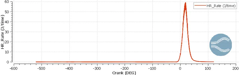
'ca' is abbrevated as crank angle followed by different stages of combustion process. Ca10 represents the start of ignition, Ca50 represents the midpoint of ignition and ca90 represents the end point of ignition. Crank angle (ca) between 10 to 90 are calculated to analyze the duration of combustion. Combustion phase angles of heat release are determined by integrating the Apparent Heat Release Rate(AHRR).
Mesh
Temperature variation animation :