Week 10: Project 1 - FULL HYDRO case set up (PFI)
Aim:
To came upon a combustion simulation with the small print given within the challenge and to review completely different properties of combustion by post process the results obtained by the calculation of the total fluid mechanics set up of the given pure mathematics.
Objective :
1. what's the compression quantitative relation of this engine?
2. Why we tend to|can we|will we} would like a wall heat transfer model? Why cannot we predict the wall temperature from the CFD simulation?
3. Calculate the combustion potency of this engine
4. use the engine performance calculator, to see the facility and force for this engine.
Geometry:
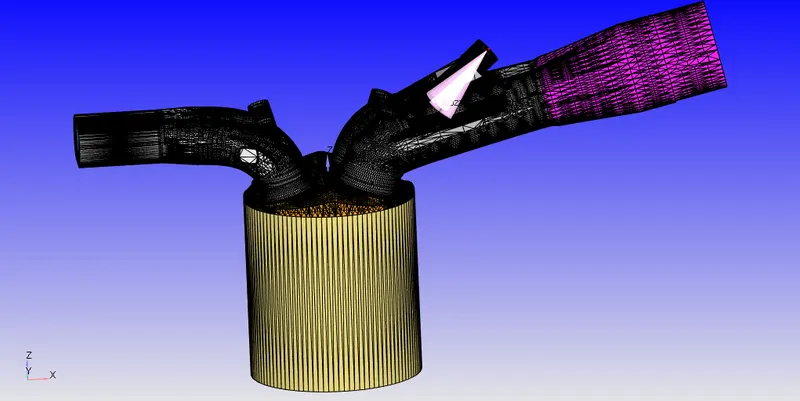
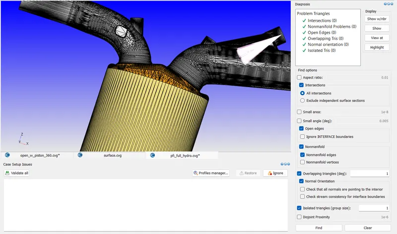
The surface preperation and boundary tired of the pure mathematics area unit exhausted the previous 1/2 the project.
Once the specified error-free pure mathematics is prepared, the complete hydro case will be got wind of victimisation the data given within the challenge.
Case got wind of for Full Hydro Simulation :
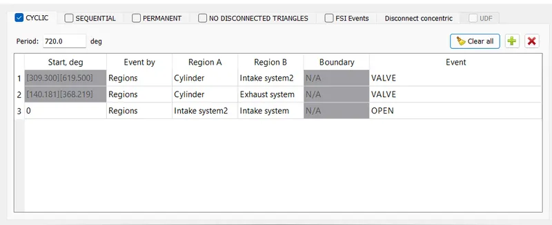
The application kind is about to Crank associategle based mostly as we have a tendency to area unit simulating an IC engine cylinder.
The measurements for the cylinder area unit given by refering to the given record.
Cylinder Bore : zero.086 m
Stroke : 0.09 m
Connecting rod length : zero.18 m
Crank speed : 3000 rev
Specify the reference boundaries as given below, so the motion of the simulations takes place at the correct boundaries.
Import the mech.dat and work unit.dat within the materials tree to specify the reactions happening between the materials within the cylinder throughout combustion.
In the run parameters, got wind of a transient simulation and choose No hydraulics problem solver as simulation mode. The gas flow problem solver is about to be compressible.
The simulation time parameter is about from -480 degree to 240 degree because the simulation is created to run a complete of 720 degree angle.
Boundary Conditions:
Engine Geometric Parameters
- Bore =0.086 m
- Stroke = 0.09 m
- Connecting rod length = 0.18 m
- RPM = 3000
Run parameters
- Simulation mode: No Hydro
Simulation time parameters
- Start time : -520 deg
- end time : 120 deg
Boundary conditions
- Piston temperature - 450K
- Liner temperature - 450K
- Head temperature - 450K
- Spark Plug temperature - 550K
- Spark Plug electrode temperature - 600K
- Exhaust ports temperature - 500K
- Exhaut outflow - 1 bar
- Exhaust outlflow temperature - 800k
- Exhaust species concentration - Calculate the stoichiometric condition
- Exhaust valve top temperature - 525K
- Exhaust valve angle temperature - 525K
- Exhaust valve bottom temeprature - 525K
- Intake port - 1 temperature 425K
- Intake port - 2 temperature 425K
- Inflow pressure - 1 bar total pressure
- Inflow temperature - 363K
- Inflow species - Air
- Intake valve top temperature - 480K
- Intake valve angle temperature - 480K
- Intake valve bottom temeprature - 480K
Initial conditions
- Intake port - 1 (closer to combustion chamber)
- ic8h18 - 0.025508
- o2 - 0.20157
- n2 - 0.77292
- Temperature - 390k
- pressure - 1 bar
- Intake port - 2 (away from combustion chamber)
- Air
- Temperature - 370K
- Pressure - 1 bar
- Cylinder
- Pressure - 1.85731 bar
- Temperature - 1360K
- Stoichiometric composition
Injection Parameters
- Fuel flow rate = 7.5e-4 Kg/second
- Injection start time = -480.0
- Injection duration = 191.2
- Fuel temperature = 330K
Nozzle positions
Nozzle diameter = 250 micro-meter
Circular injection radius = Nozzle radius
Spray cone angle = 10
- Nozzle 0
- center 0.0823357 0.00100001 0.07019
- Align Vector -0.732501 0.210489 -0.647408
- Nozzle 1
- center 0.0823357 -0.00099999 0.07019
- Align Vector -0.732501 -0.210489 -0.647408
- Nozzle 2
- center 0.0823357 -0.0004 0.07019
- Align Vector -0.5 -0.2 -0.647408
- Nozzle 3
- center 0.0823357 0.0003 0.07019
- Align Vector -0.5 0.2 -0.647408
Spark Ignition Parameters
- Start of spark = -15 deg
- Spark duration = 10 deg
- Spark location = -0.003 0 0.0091
- Spark radius = 0.0005m
Spray Modelling:
CONVERGE includes progressive physical models for a good type of phenomena, together with chemistry, turbulence, point fluid flow, spray, and radiation, and it mechanically couples these models therefore you don’t got to. If you’re searching for a shorter runtime, you'll be able to opt for one among CONVERGE’s simplified combustion models. If accuracy is predominant, CONVERGE’s elaborate chemical dynamics convergent thinker can assist you acquire the results you wish. For turbulence modeling, you'll be able to make a choice from a bunch of each RANS and LES models. For spray modeling, CONVERGE will capture physical processes from liquid injection and spray breakup to drop/wall interaction and evaporation. CONVERGE conjointly includes many volume of fluid modeling choices to simulate multi-phase flows.
Select the spray modeling parameter within the physics models. within the spray modeling we tend to ar mistreatment O'Rourke model to initialise the spray of fuel.
The species to be injected is chosen because the fuel part IC8H18, that is chosen because the parcel particle within the materials properties.
The following parameter values ar introduced for the specifications of mechanical system.
Fuel rate of flow = seven.5e-4 Kg/second
Injection begin time = -480.0
Injection length = 191.2
Fuel temperature = 330K
The Kelvin-Helmholtz (KH), Rayleigh-Taylor (RT) & Discharge constant models ar being employed for the injection.
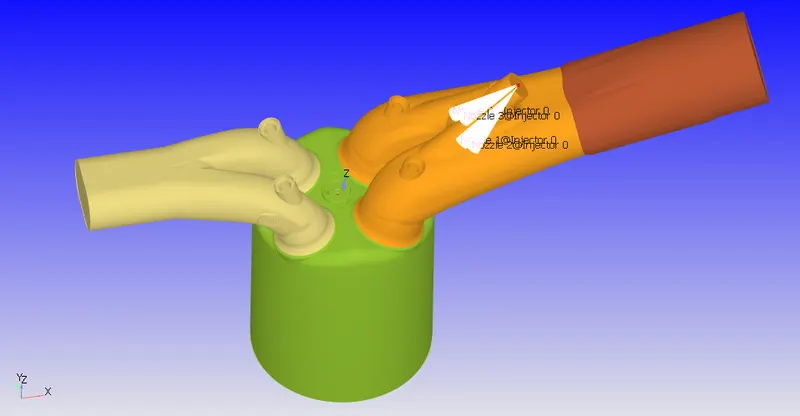
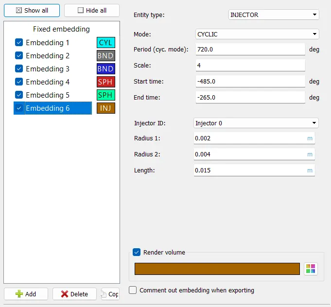
Here, we tend to ar mistreatment four nozzles for spraying the fuel into to the cylinder with similar specifications as follows.
Nozzle diameter = 250 micro-meter
Circular injection radius = Nozzle radius
Spray cone angle = ten
To initialise this method, Coordinates of the injectors ar required to make your mind up the placement at that the fuel is being emerged into the cylinder. The injectors are going to be settled within the import region-1 that is found close to the cylinder.
Nozzle 0
center [0.0823357; 0.00100001; 0.07019]
Align Vector [-0.732501; 0.210489; -0.647408]
Nozzle 1
center [0.0823357; -0.00099999; 0.07019]
Align Vector [-0.732501; -0.210489; -0.647408]
Nozzle 2
center [0.0823357; -0.0004; 0.07019]
Align Vector [-0.5; -0.2; -0.647408]
Nozzle 3
center [0.0823357; 0.0003; 0.07019]
Align Vector [-0.5; 0.2; -0.647408]
Combustion chamber:
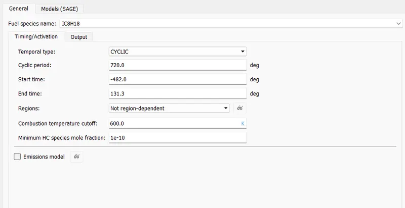
CONVERGE’s SAGE elaborate chemistry thinker uses native conditions to calculate reaction rates supported the principles of chemical mechanics. This {solver|problem thinker|convergent thinker|thinker} is totally coupled to the flow solver, however the chemistry and therefore the flow solvers place severally of 1 another, that quickens the simulation. With the suitable mechanism, the SAGE thinker will predict a large vary of cases (e.g., a range of fuels [premixed, non-premixed, part premixed, multiple fuels], emissions modeling, and distinctive phenomena like end-gas auto-ignition). With its accuracy and strength, CONVERGE will perform prognostic modeling rather than simply confirming experimental results.
The next step within the modeling is that the combustion modeling parameter. The values for the combustion properties like begin time, finish time & species is to be such as given within the image below.
The combustion model here is taken because the SAGE model. The turbulence model is taken because the RNG K-Eppsilon model.
Source Modeling :
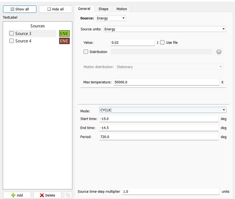
Then the supply of power ought to be per order to ignite the incoming fuel throughout the compression of the fuel. For this choose supply modeling underneath the physics modeling.
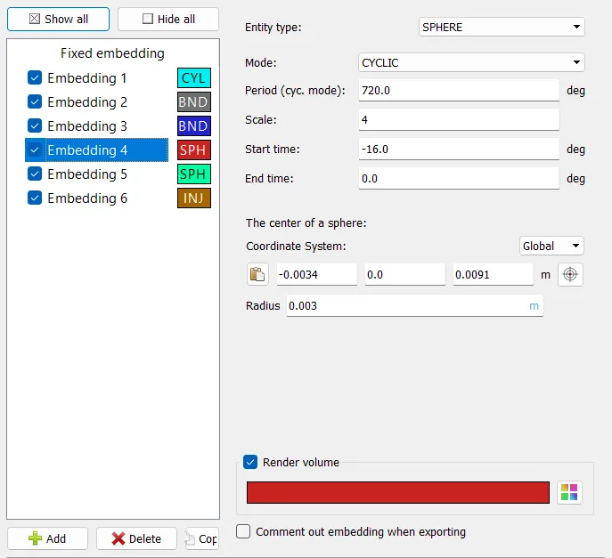
In the supply modeling add 2 sources wherever each the sources have a spherical form.
Spark location = -0.003 0 0.0091
Spark radius = zero.0005m
The spark location and radius specifies the spherical volume wherever the ignite starts.
The amount for the spark is given in degree.
Grid:
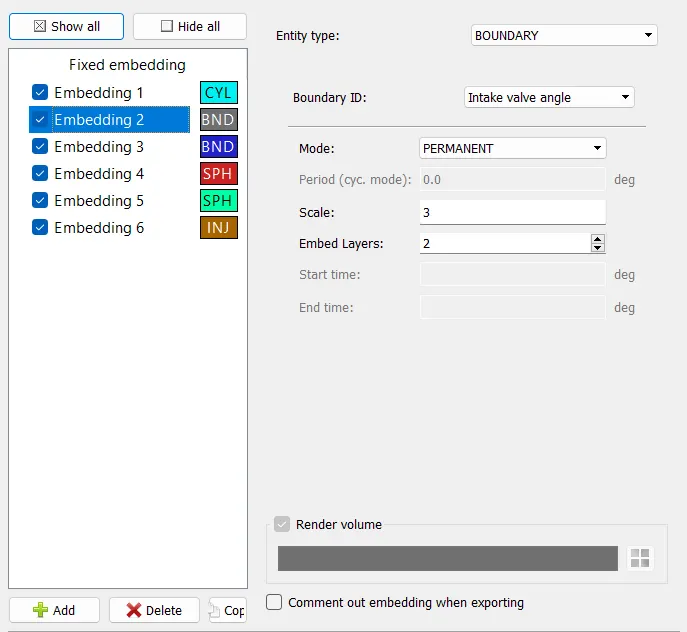
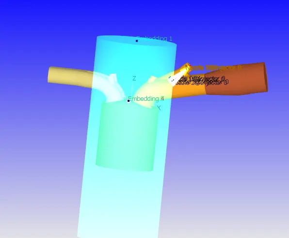
The grid size is taken to be zero.004 m and glued embeddings square measure done at essential points.
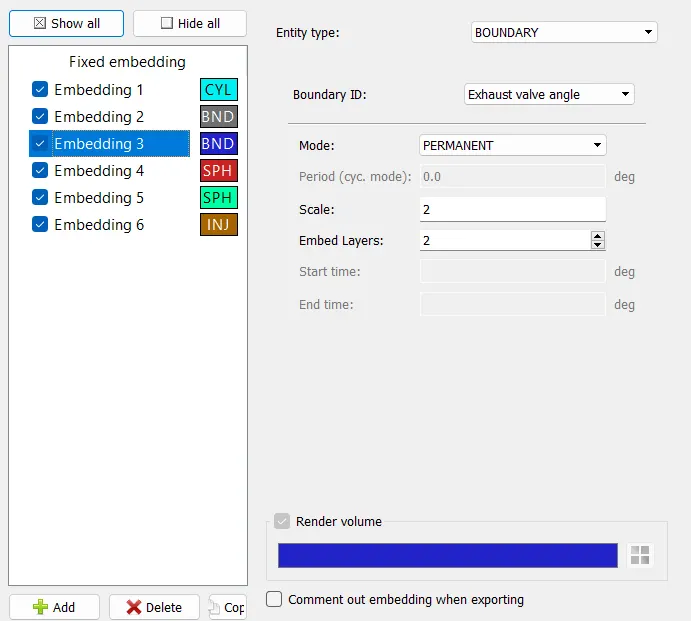
The valve angles square measure supplied with a scaling of three as they're moving therefore near to the walls of the plate.
The mesh within the cylinder is additionally refined to a scale of two because the combustion is captured properely.
Fixed Embedding :
To refine that essential space, we are able to use mounted Embedding round the Throttle Boundary.
fixed embedding is employed to refine the grid at specific locations within the domain wherever a finer resolution is essential to the accuracy of the answer. mounted embedding permits the remainder of the grid to stay coarse to reduce simulation time.
For each mounted embedding, you want to specify AN embedding scale that indicates however CONVERGE can refine the grid therein location. The embed_scale parameter, that should be a positive whole number, scales the bottom grid sizes (dx_base, dy_base, and dz_base) consistent with
dx_embed = dx_base/2^embed_scale.
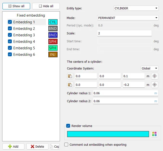
Note that CONVERGE needs two-to-one property between cells, i.e., a cell with AN embed_scale of two is adjacent solely to a cell with AN embed_scale of one, 2, or 3. to take care of the specified property, CONVERGE provides cells with intermediate embed_scale values as necessary.
Adaptive Mesh Refnement :
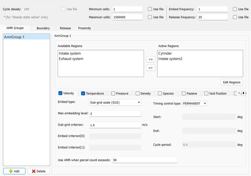
CONVERGE’s innovative adaptational Mesh Refinement (AMR) technology mechanically adjusts the grid at every time-step, adding cells in areas with complicated phenomena and eliminating cells that aren't required to yield correct results. This strategic refinement ensures that CONVERGE will resolve flame fronts and fast flows whereas minimizing the general cell count.
This adaptational Mesh Refinement (AMR) method adds native refinement in areas of steep field variable gradients and is currently additionally being pursued by several of the opposite leading CFD package OEMs. the corporate calls the method "Autonomous meshing" and argues the subsequent benefits:
By eliminating the method of manual mesh creation, examination and refinement, time is saved
Accuracy is improved through higher grid density wherever it's required and wherever manual meshing methods may not allot it AMR provides a strong technique for capturing giant or speedy boundary motions
AMR provides run-time savings because of victimisation associate degree optimized range of procedure cells Consistency and standardization will be achieved through the employment of a homogenous, algorithmic strategy for mesh production.
Adaptive mesh refinement is completed to capture the places at that the properties of the calculation area unit important.
The refinement is formed to be adaptational for rate and temperature.
The parameters for each the properties area unit nominal so the mesh adapts the values from the specification to refine the places wherever the values tend to be among the desired parameter.
Power Calculation :
To calculate power we can use the formula; Power = Work/sec
From performance calculator we can take;
Work = 486.646 Nm
Start time = -120.09 deg
End time = 120.11 deg
Total duration = 240.199 deg
Total rotation per minute RPM = 3000 (Given)
Rotation per second = 3000/60 = 50.
Total degree per second = 50*360 = 18000
Time in sec = 240.199/18000 = 0.01334 sec.
Power = 486.646/0.01334
Power = 35130.88 Kj = 35.13 KW
Torque Calculation :
power = (2*pi*N*T)/60
T = power * 60/ (2*pi*N)
N = 3000 RPM.
T = 35.13 *1000* 60 / (2*3.14*3000) = 2107.8/18840
Torque(T) = 111.879 Nm.
Expected motion of the Engine :
An enclosed combustion (IC) engine within which the piston completes four separate strokes whereas turning the rotating shaft. A stroke refers to the complete travel of the piston on the cylinder, in either direction. The four separate strokes square measure termed:
Intake:
Conjointly referred to as induction or suction. This stroke of the piston begins at high dead centre (T.D.C.) and ends inside dead centre (B.D.C.). during this stroke the valve should be within the open position whereas the piston pulls associate degree air-fuel mixture into the cylinder by manufacturing vacuum pressure into the cylinder through its downward motion. The piston is moving down as air is being sucked in by the downward motion against the piston.
Compression: This stroke begins at B.D.C, or simply at the top of the suction stroke, and ends at T.D.C. during this stroke the piston compresses the air-fuel mixture in preparation for ignition throughout the facility stroke (below). each the intake and exhaust valves square measure closed throughout this stage.
Combustion: conjointly referred to as power or ignition. this is often the beginning of the second revolution of the four stroke cycle. At this time the rotating shaft has completed a full 360 degree revolution. whereas the piston is at T.D.C. (the finish of the compression stroke) the compressed air-fuel mixture is lit by a sparking plug (in a gas engine) or by heat generated by high compression (diesel engines), forcefully returning the piston to B.D.C. This stroke produces mechanical work from the engine to show the rotating shaft.
Exhaust: conjointly referred to as outlet. throughout the exhaust stroke, the piston, once again, returns from B.D.C. to T.D.C. whereas the valve is open. This action expels the spent air-fuel mixture through the valve.
Why can we want a wall heat transfer model?
Internal combustion engines area unit currently very optimized, in such ways in which up their performance may be a expensive task. ancient engine improvement by experimental suggests that is power-assisted by engine physical science models, reducing experimental and total project prices. For those models, accuracy is obligatory so as to supply smart prediction of engine performance.
Modelling of the warmth transfer and wall temperature is a very important task regarding the accuracy and therefore the predictions of any engine physical science model, though it's associate degreed again|over and over} an overcome task. so as to perform smart prediction of engine heat transfer and wall temperature, models area unit needed for accomplish heat transfer from hot gases to engine components, heat transfer within every engine half, and additionally heat transfer to agent and grease.
Why cannot we have a tendency to predict the wall temperature from the CFD simulation?
The elaborate procedure Fluid Dynamic (CFD) modeling methodology was developed victimisation FLUENT. Eulerian two-phase flow model is employed to model the flow and warmth transfer phenomena. so as to realize the height wall temperature accurately and stably, the impact totally different|of various} turbulence models and wall functions area unit investigated supported different grids. Results show that O kind grid ought to be used for the simulation of CHF development. Grids with Y+ larger than seventy area unit counseled for the CHF simulation as a result of the suitable results of all the turbulence models whereas Grids with Y+ not up to fifty ought to be avoided. To predict the dry-out position accurately in an exceedingly fine grid, Realizable k-ε model with customary wall perform is suggested. These conclusions have some reference significance to higher predict the CHF phenomena of vertical pipe. It may be expanded to rod bundle of Boiling Water Reactor (BWR) by victimisation same pressure condition.
So the wall temperature obtained victimisation the CFD calculations area unit the temperature of the fluid around the wall of the cylinder, that isn't the most effective result. so the wall heat transfer model is employed to predit the wall temperature.
Calculate the combustion potency of this engine
In real engine applications, the combustion method is incomplete. this implies that not all the energy content of the fuel provided to the engine is free through the combustion method. There area unit many factors which may influence the combustion method, the foremost vital being the fuel-air intake and fuel atomization (size of droplets). The fuel within the cylinder wants air (oxygen) to burn. If there's not enough O on the market, not all the fuel is burnt, thus solely a partial energy is free from combustion (e.g. around ninety six %). If we have a tendency to analyze the exhaust gas of an interior combustion engine, we are able to see that it contains each incomplete combustion product (carbon oxide CO, N oxides Roman deity, unburnt hydrocarbons HC, soot PM) and complete combustion product (carbon oxide CO2 and water H2O).
The combustion potency potency is outlined because the magnitude relation between the energy free by the burnt fuel and therefore the theoretical energy content of the fuel mass throughout one complete engine.
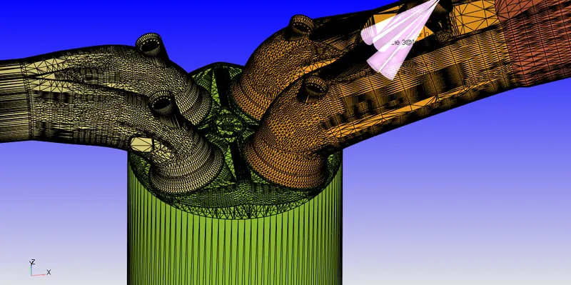
The embedding given to the bottom grids provides US a finner and neat end on some important areas wherever the calculated values could also be a lot of necessary.
The embedding at the nozzles is clearly shows a refined mesh within the 1st image. equally the embedding round the plug is additionally refined which might be clearly seen within the second image.
Other embeddings and also the reconciling mesh refinement will be clearly seen through animation wherever we are able to see the refined mesh dynamical in step with the sgs parameter that is such for each speed and temperature values throughout the calculation.
From the animation we are able to see that when ignition the meshes close to the walls gets refined because the sgs parameters such matches the requirment once the temperature suddenly raises close to the wall.