Week 10: Project 1 - FULL HYDRO case set up (PFI)
Aim: To simulate the port fuel injection engine in converge CFD by using hydro simulation and calculate the important parameters like Compression ratio, Power, Combustion efficiency, and Torque.
Theory:
Fuel injection is the introduction of fuel in an IC engine, most commonly automotive engines, through an injector. Fuel injection replaced carburetors from the 1980s onward. The main difference between carburetion and fuel injection is that fuel injection atomizes the fuel through a small nozzle under high pressure, while a carburetor relies on suction created by intake air accelerated through a Venturi tube to draw the fuel into the airstream.
Historically, the most widely produced internal combustion engines were of the Port Fuel Injected (PFI) design, where the fuel is sprayed into the intake ports to mix with incoming air. In fact, many new vehicles are still manufactured with this engine design. The fuel injectors in PFI configurations are typically mounted in the intake manifold and the air/fuel mixture is pulled into the cylinder head as the intake valve opens.
Case setup:
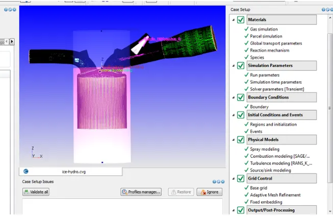
The geometry and case setup almost the same as the previous challenge (spark fuel engine with no hydro). Here hydro is using in the PFI engine. Select parcel simulation, and species in materials.
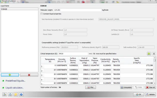
• Parcel simulation is required to simulate the fuel spray droplets as parcels which are required to simulate the combustion reaction. Click on predefined liquids and select IC8H18 (IsoOctane) as fuel because its properties are similar to gasoline fuel. In species > click on parcels > and select IC8H18.
• In Run parameters select full hydrodynamic in simulation mode.
Physical models:
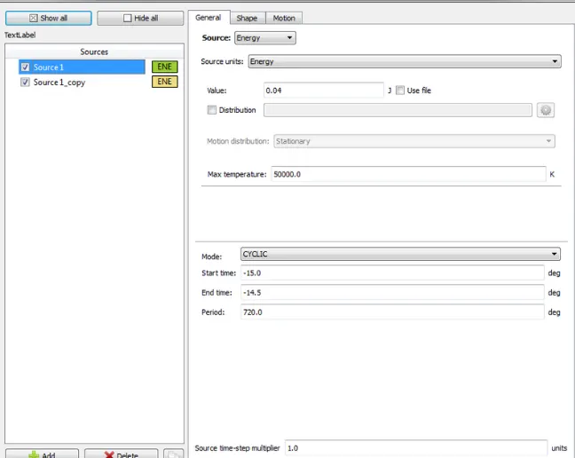
Select Spray, Combustion, and Source/Sink modeling.
Spray modeling is used to configure nozzles, injectors, boundary injections, injection rate shapes, set various spray-related constants, and choose from several injection and drop models. Spray modeling is very important to obtain accurate solutions for predictive combustion simulations. Converge has a variety of spray modeling options. Here, we are using the O'rouke model for the turbulent dispersion of spray parcels
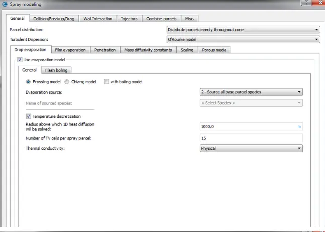
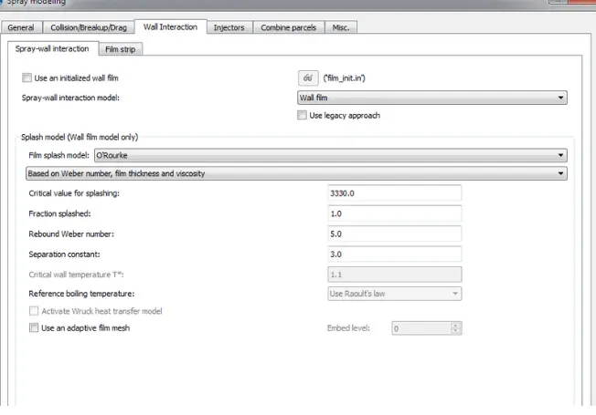
under injector click one add
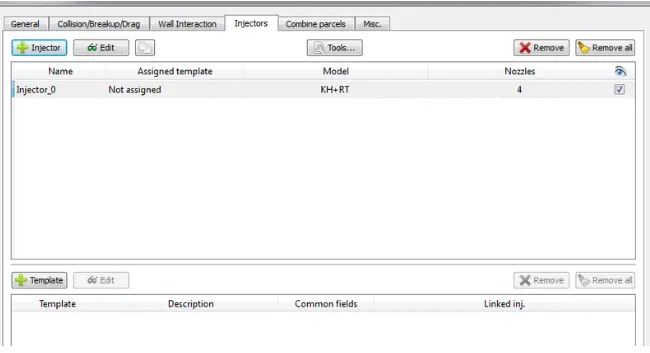
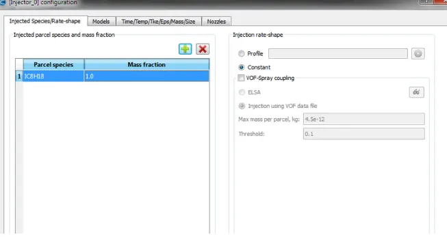
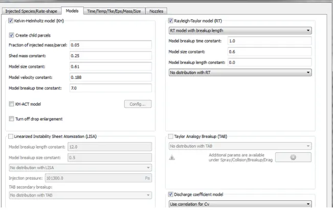
Select the Kelvin-Helmholtz and Rayleigh-Taylor models.
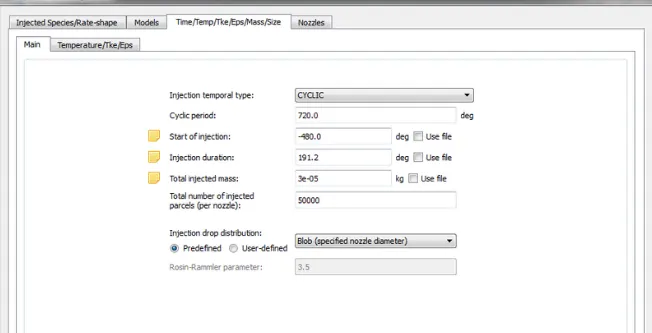
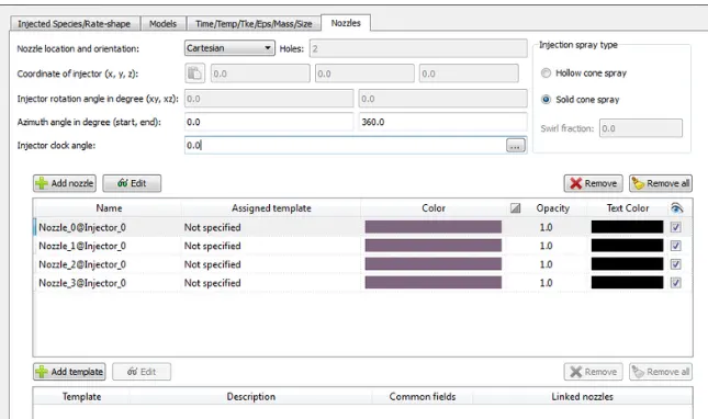
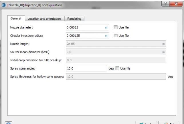
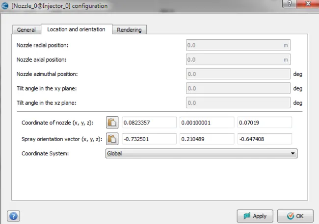
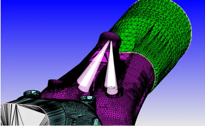
Add 4 nozzles in the nozzle as shown in the fig below.
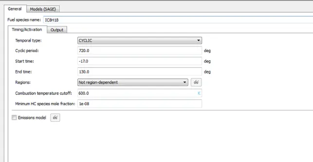
Combustion modeling:
Source/Sink modeling:
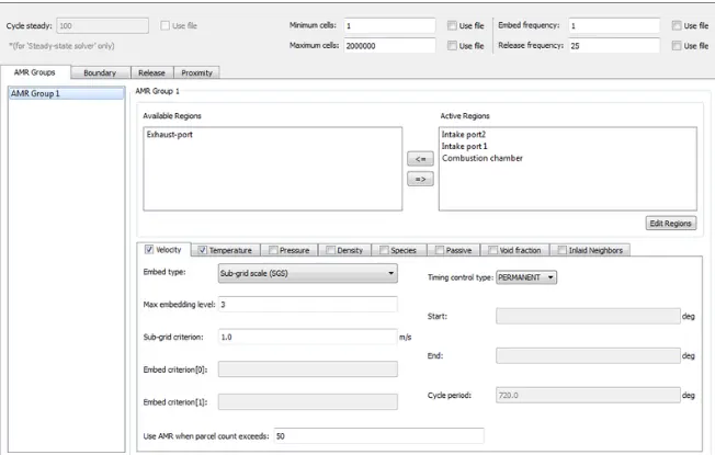
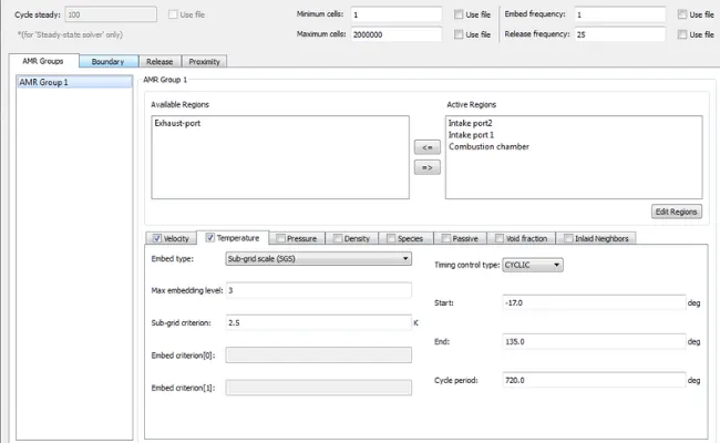
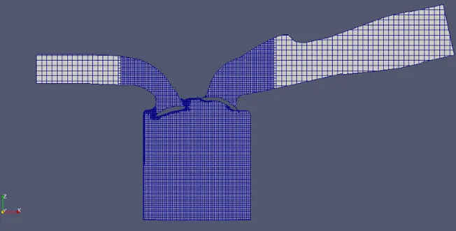
Adaptive mesh refinement:
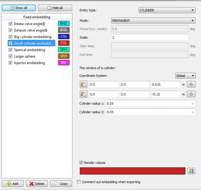
Fixed embedding:

Export all files and run the simulation.
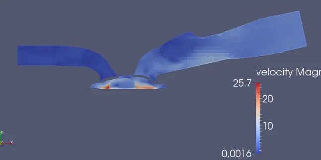
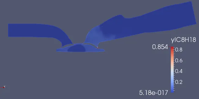
Simulation results:
l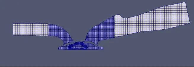
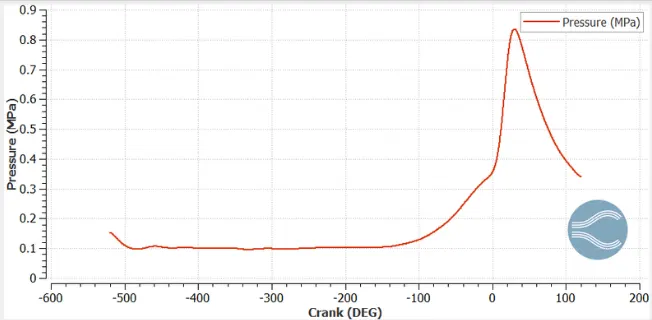
1. Calculating Compression ratio: It is defined as ratio of max. volume/min. volume.
compression ratio,
From the volume plot as shown below.
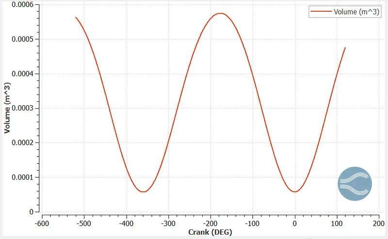
we have minimum volume at -360 deg, i.e,
also we have maximum volume at -176.35 deg i.e,
therefore compression ratio,
2. Calculating the combustion efficiency of the engine: It is defined as ratio of energy released by the burnt fuel to and the theoretical energy content of the fuel mass during one complete engine cycle.
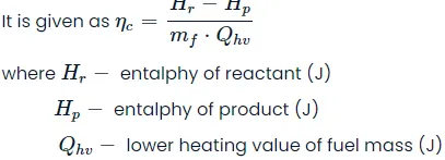
As far as simulations are concerned the numerator part is calculated using the integated heat release plot, as shown below
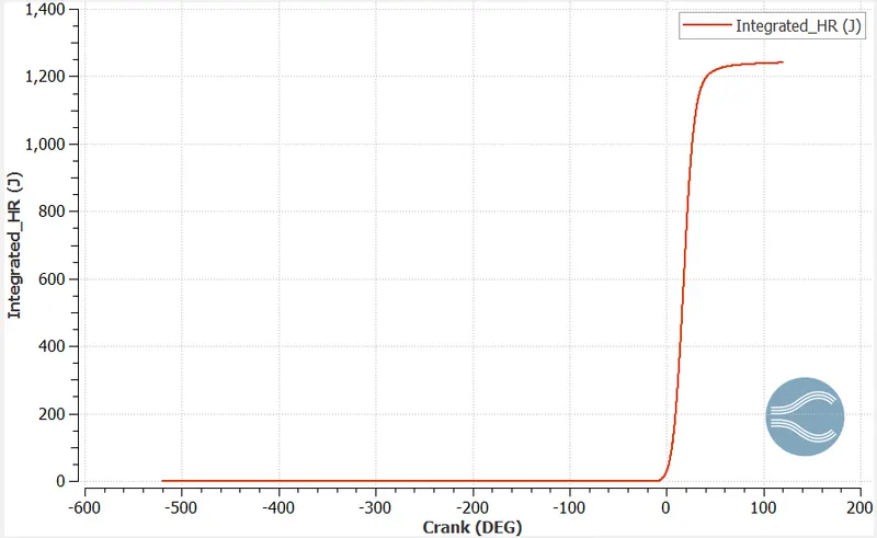
from the above plot we have integrated_HR = 1241.04 J
Lower heating value of
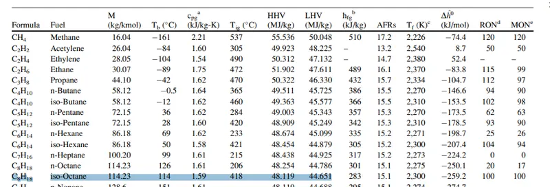
mass of fuel injected per cycle = 3e-05 kg
therefor heat generated per cycle = 3e-05*44.651*e06 J
= 1339.53 Joules
3. Calculating power and torque of the engine:
Workdone by an engine is given by the formula,
where w - workdone (N-m, J)
T - torque (N-m)
from engine performance calculator we have workdone , w = 468.646 N-m
therfore torque, T = w/
Torque, T = 468.646/4.192106 = 111.7924 N-m
Power, P=2*π*N*t/60
P - power (J/s)
N - engine speed (rpm)
T - torqu (N-m)
therfore Power, P = 2*
OR
we have Power given as P = Workdone/time
we have engine speed given as 3000 rpm, i.e 3000 rotation for 60 sec
so 1 rotation = 360 degree, so 360*3000 degree of rotation for 60 sec, from this we can calculate time taken in second for rotating
1 deg = 60/3000*360 = 5.55e-05 sec/deg from the engine performance calculator we have the duration (in degree) for which the workdone
is calculated which is = 240.199 degree.
so time taken for rotating 240.199 degree = 240.199*5.55*e-05 = 0.01333 sec.
therefore Power, P = 468.646/0.01333 = 35.236 KJ/sec
P = 2*
T = P*60/(2*
Power and torque can be calculated anyway around, which approximates to almost same answer.
* Engine performance calculator is a tool that can be used to calculate engine power, imep etc of the engine. Thermo_0 file for the cylinder region is used to calculate the engne power and imep. A snip of the same is given below,
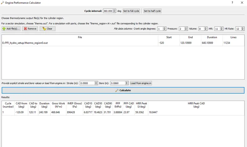
* In the above engine performance calculator we can find CAD10, 50 and 90 these represents the crank angle at which 10%, 50% and 90% of combustion has taken place, physical significance of CA10 is that it is used to identify the start of ignition of fuel present in the engine whereas CA50 indicates the end of premixed combustion and start of diffusion combustion of the fuel used in the engine. CA90 signfies the end of diffusion combustion.
4. Why do we need a wall heat transfer model:
In order to perform a good prediction of engine heat transfer and wall temperature, models are required to accomplish heat transfer from hot gases to engine parts, heat transfer inside each engine part, and also heat transfer to coolant and lubricating oil. We can't predict wall heat transfer because we are simulating only the fluid flow and heat transfer only inside the flow domain and we are not simulating the heat conduction inside the solid part.
5. Significance of ca10, ca50, and ca90:
The Crank angle(ca) CA10, CA50, and ca90 are defined as the crank angle (deg) position at which the cumulative heat release reaches 10%, 50%, and 90% respectively.
The calculated value of the PFI engine for CA10 is 6.837 degrees, for CA50 is 18.46 degrees, and for CA90 is 31.701 degrees.
Conclusion:
- Port fuel injection IC engine with hydro simulation was setup and successfully run in converge.
- Various plots and calculations were made and the results of the simulation were studied.
Animation of cylinder