Week - 10 Hyperelastic Material Models
Aim : perform a material modeling for hyper elastic material with given data and verify the same with simulation
Procedure :
1st open image and extract the image data , plot the stress vs strain graph for engg stress and engg strain
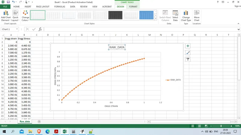
we will use this engineering stress and engineering strain grapg to define the hyperelastic material
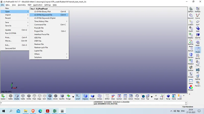
now open tensile test mesh file in LS Prepost
file >> open >> LS PrePost keyword file
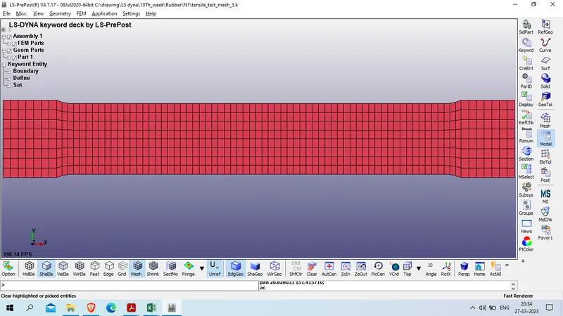
Case 1 : Model setup for Mooney Rivlin
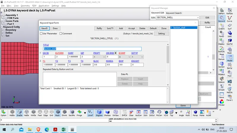
Create section card for this dogbone speciment
model and part >> keyword manager >> all >> section >> shell
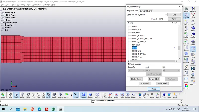
Title : Section_shell
SECID : 1
ELFORM : 2
T1/T2/T3/T4 : 1.5
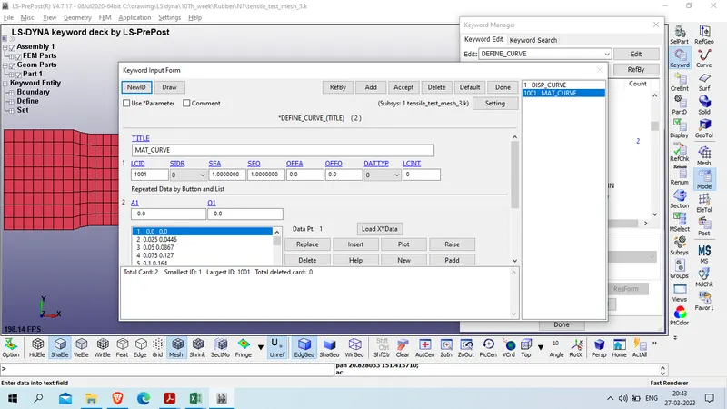
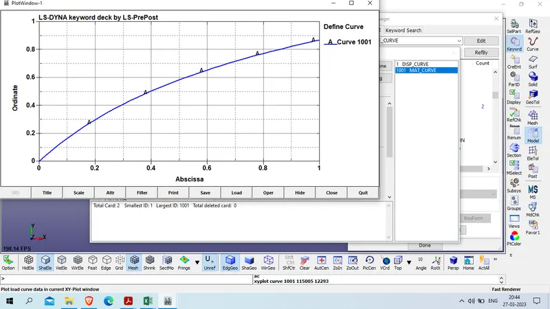
now define material curve
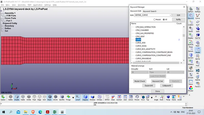
model and part >> keyword manager >> all >> define >> curve
Title : MAT_CURVE
LCID : 1001
Now create material : Hyperelastic material
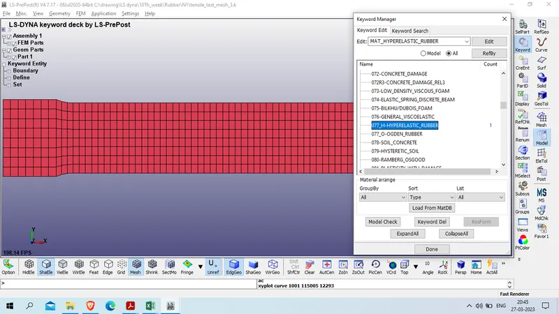
Model and part >> keyword manager >> all >> mat >> 077_H-HYPERELASTIC_Rubber
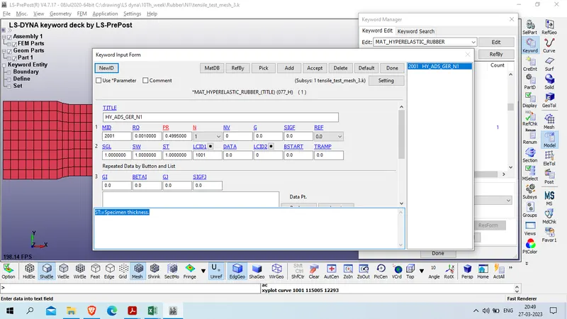
we will use gm-mm-ms unit system here
length : mm
Mass : Gram
Time : ms
STRESS : MPa
ENERGY : N-mm
Density of rubber material : 0.001gram/mm^3
Poission Ratio : 0.4995
N:=Number of constants to solve for: : 1
LCID : 1001
SGL:=Specimen gauge length. : 1
SW:=Specimen width. : 1
ST:=Specimen thickness. :1
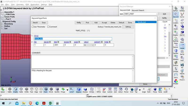
Now assign Material and section card to the part card
Model and part >> keyword manager >> model >> part >> part

Title : Tensile_test
PID : 1
Now define boundary condition for that we will 1st create node set
model and part >> create entity >>SET_DATA >> Set_node
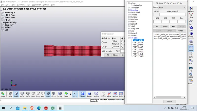
click on create and select left side node by box area selection
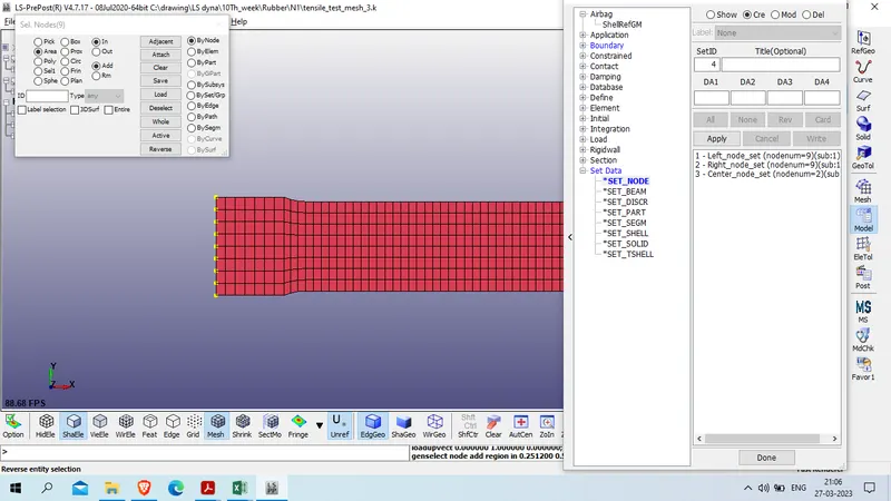
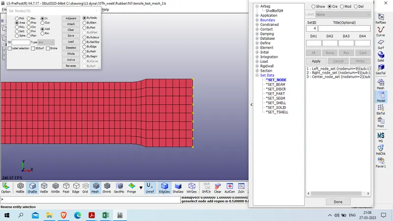
and repear same to right side node
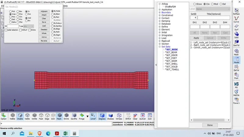
finally create center node set to fix y direction displacement
now define boundary condition , SPC
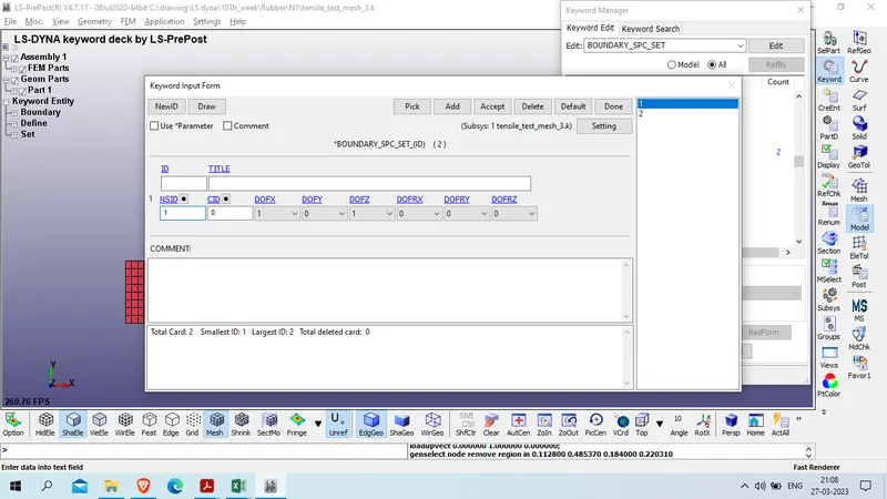
model and part >> keyword manager >> all >> boundary >> SPC_SET
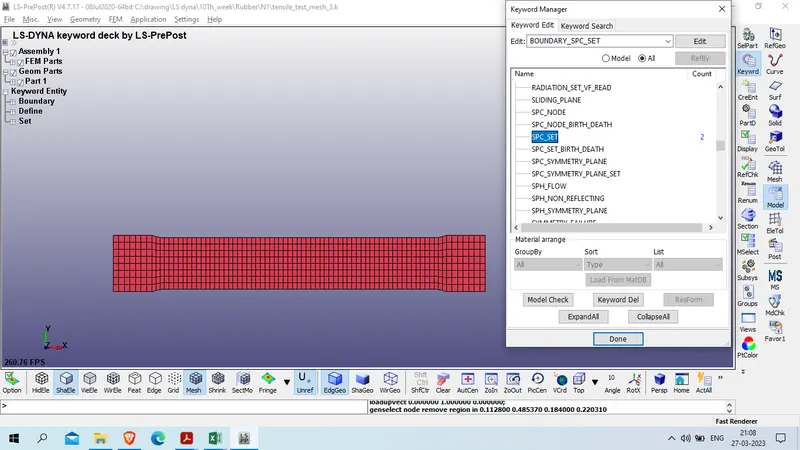
select NSID :1 and fix them in X and Z axis DOF
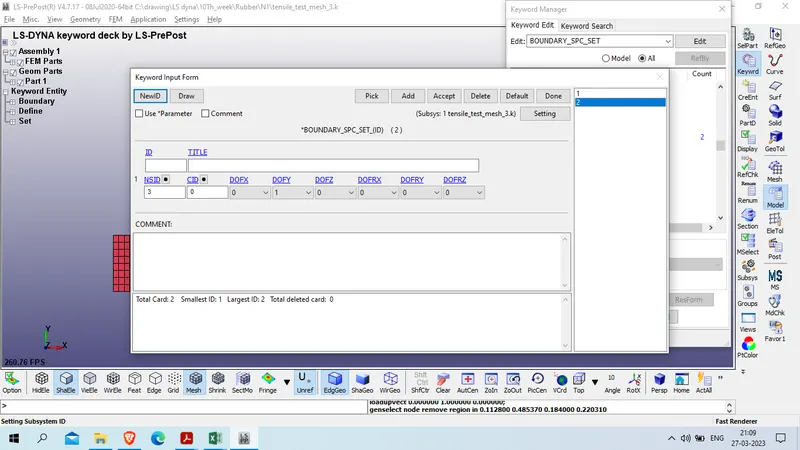
select NSID : 3 and fix them y DOF
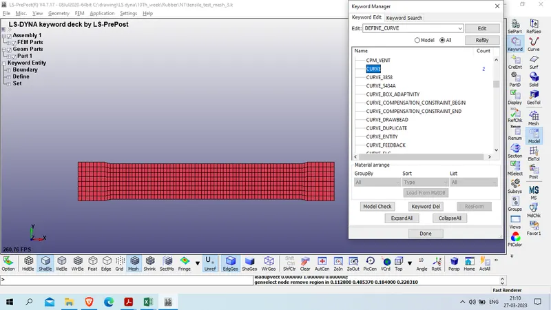
now create displacement curve , as we have to run the simulation for 100% strain and our specimen length is 145 so that we have to displace right node to 145 units
Model and part >> keyword manager >> all >> define >> curve
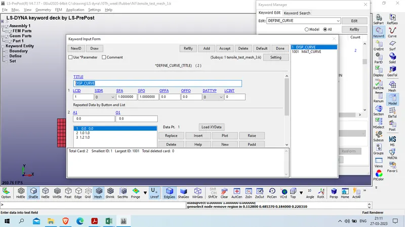
add curve
Title : DISP_CURVE
LCID : 1
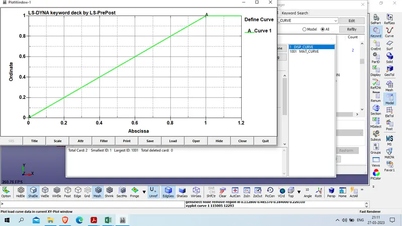
Now create prescribe motion set for right side node
model and part >> keyword manager >> all >> boundary >> prescribe_motion_set
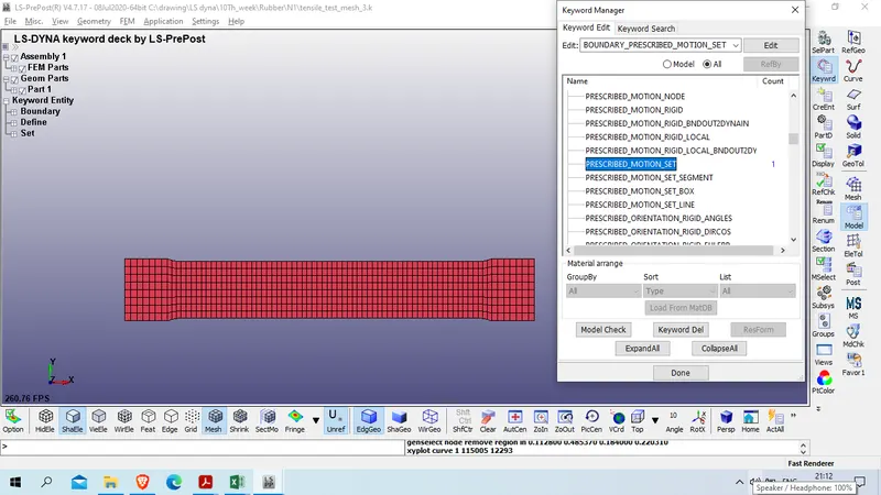
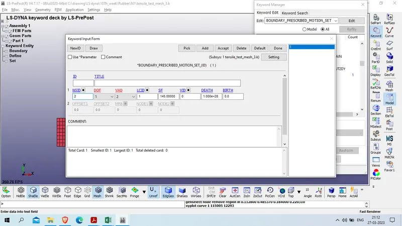
DOF: X axis : 1
VAD : 2 ( displacement )
LCID : 1
now we will define control card for this analysis as we have to run for implicit analysis , intoduce implicit auto, implicit general and implicit solver card
model and part >> keyword manager >> all >> control >> implicit_auto
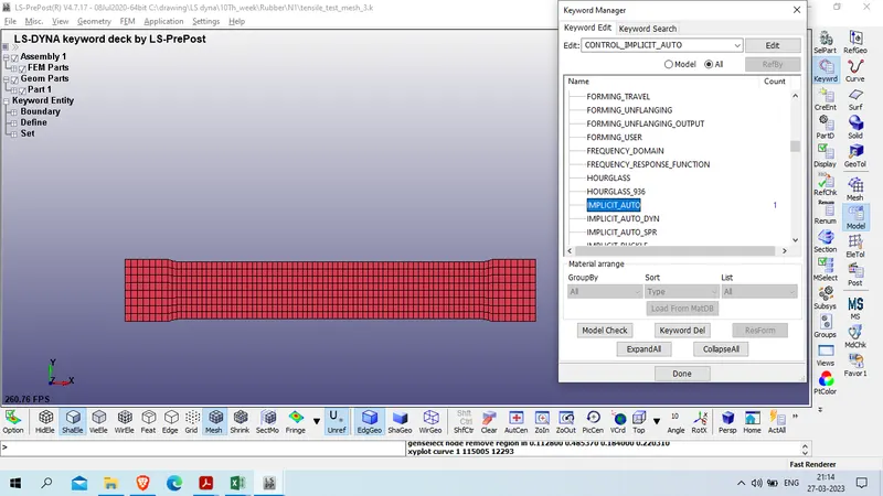
IAUTO: 1
ITEOPT: 100
DTMIN :0.01
DTMAX: 0.05
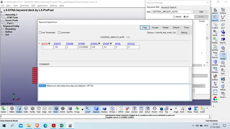
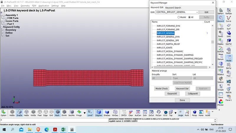
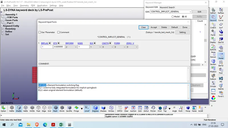
model and part >> keyword manager >> all >> control >> implicit_general
IMFLAG:= 1
DT0: 0.02
IMFORM : 2
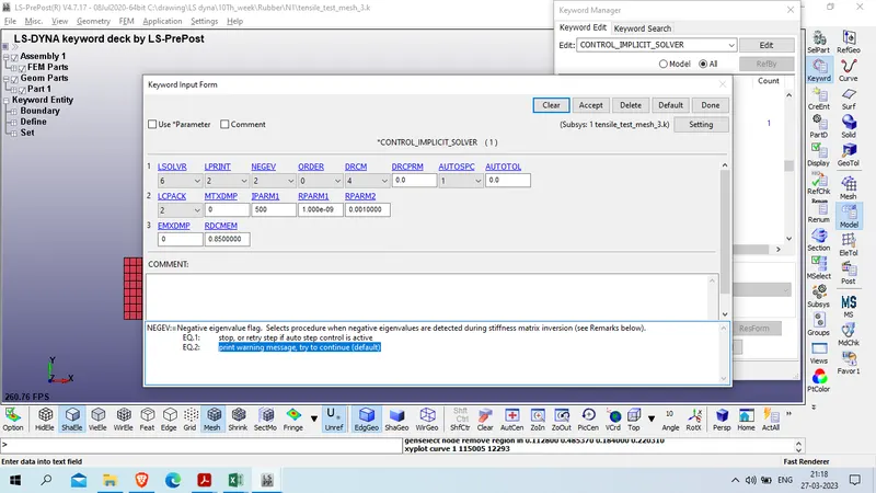
Model and part >> keyword manager >> all >> control >>Implicit_solver
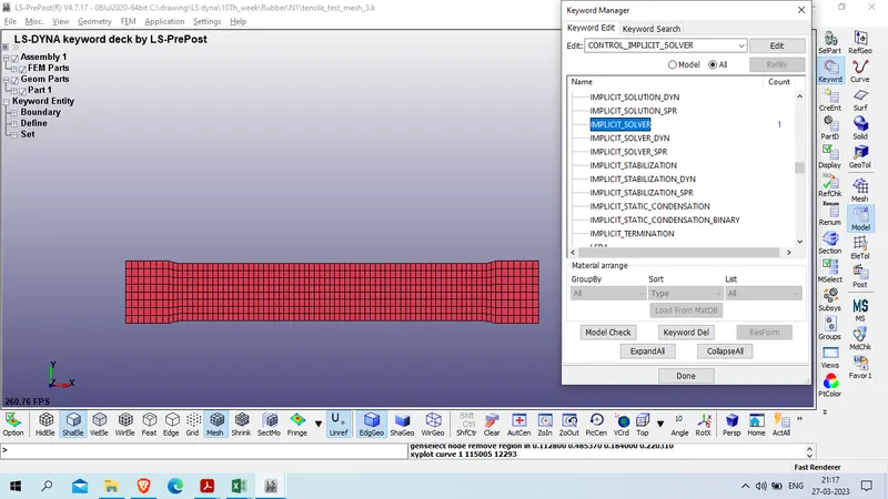
LSOLVR: 6 (BCSLIB-EXT, direct, sparse, double precision)
LPRINT: 2 (more statistics)
NEGEV: 2 (print warning message, try to continue (default))
Define termination card for this simulation
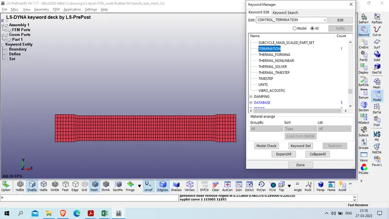
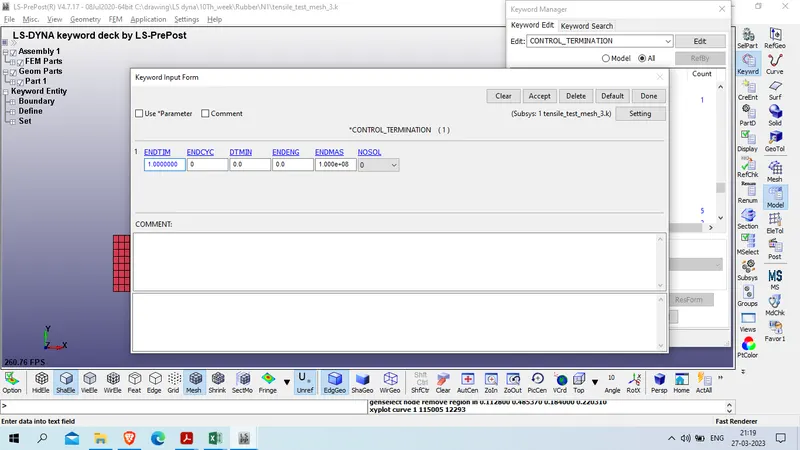
model and part >> keyword manager >> all >> control >> termination
ENDTIM : 1
now define database card for output
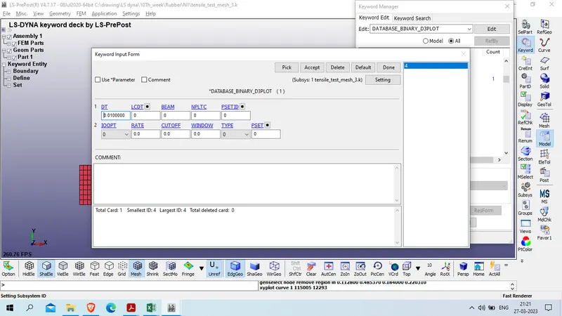
create D3PLOT card
model and part >> keyword manager >> all >> database >>BINARY_D3PLOT
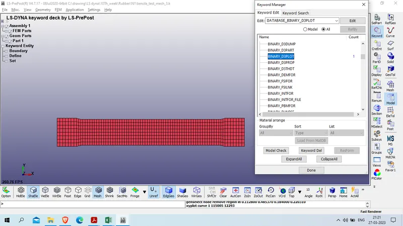
DT : 0.01
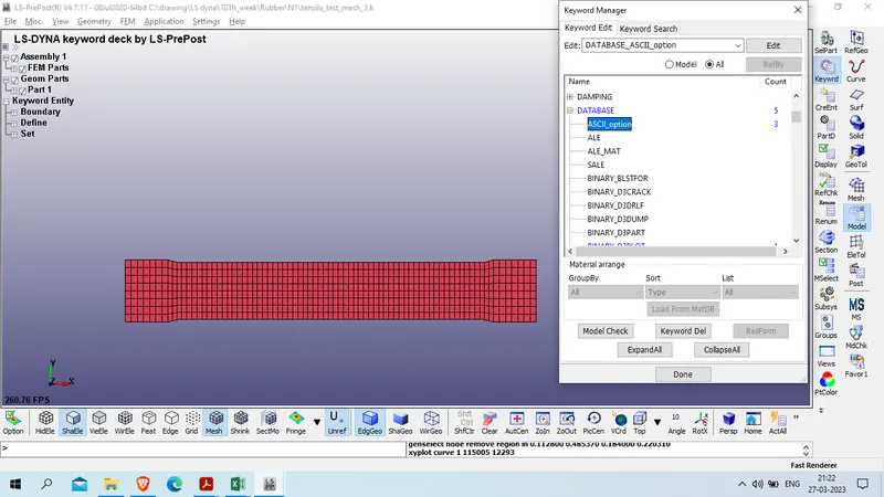
Create ASCII_OPTION card
model and part >> keyword manager >> all >> database >>ASCII_OPTION
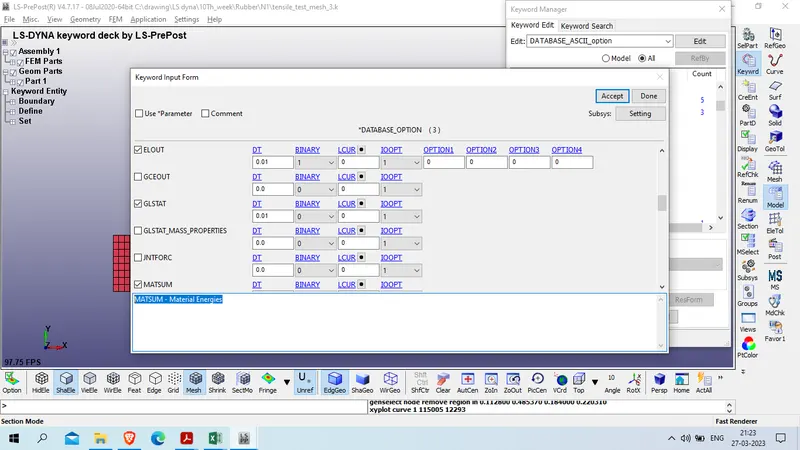
ELOUT - Element Output Data
GLSTAT - Global Statistics
MATSUM - Material Energies
Dt : 0.01
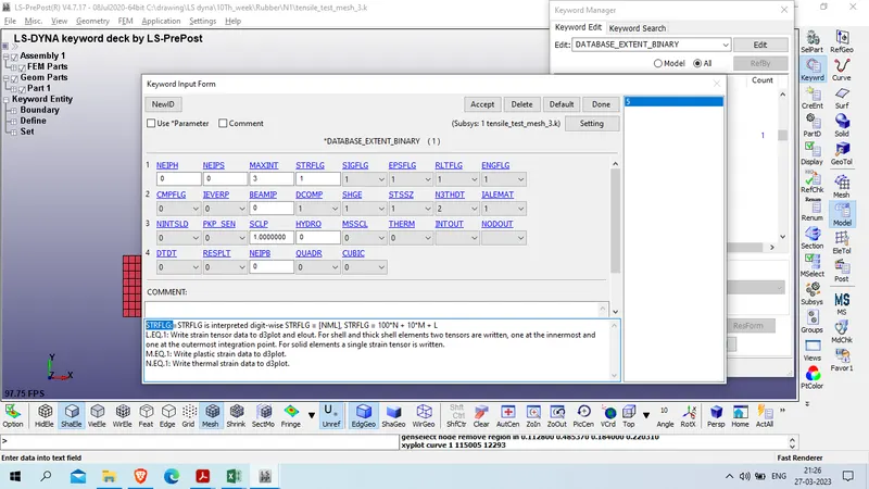
Create extend_Binary Card
model and part >> keyword manager >> all >> database >> EXTEND_BINARY
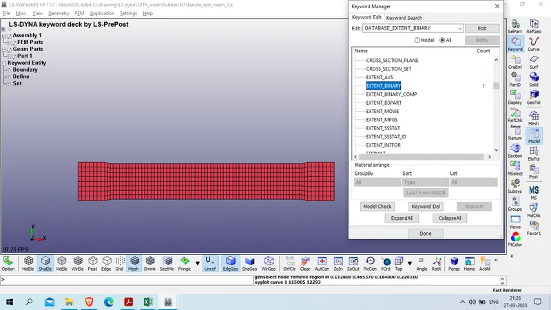
STRFLG: 1
now check for keyword error
model checking >> keyword check >> recheck

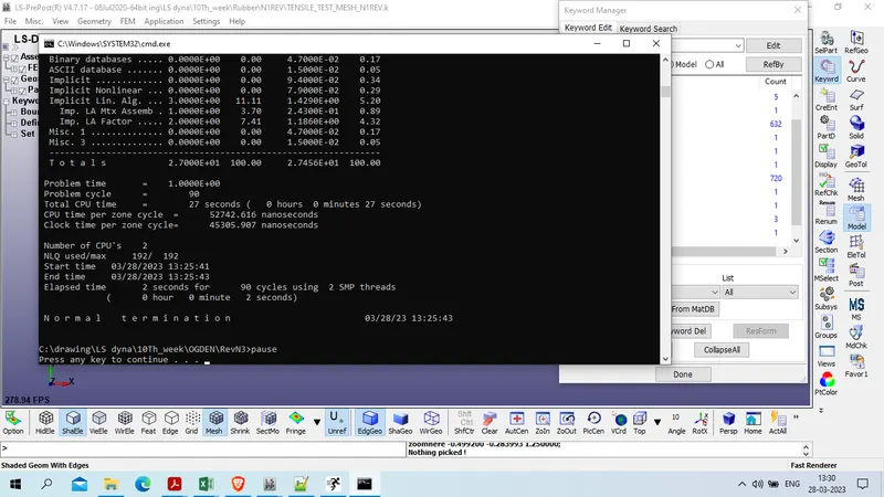
now save file and run for simulation
file >> run as LS-DYNA
Case 2 : model setup of ogden material card
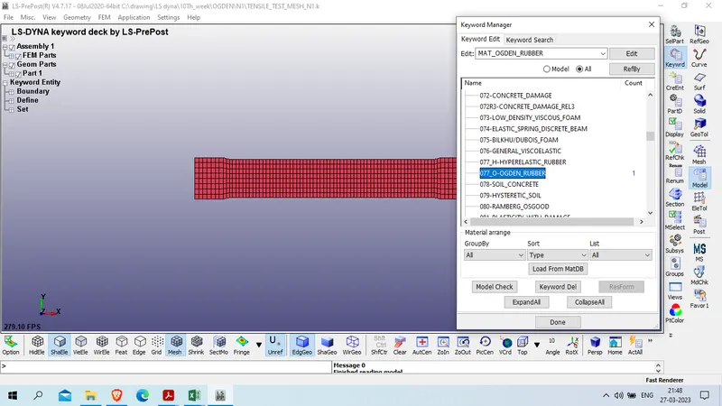
all the above setup will be same as it is only wi will use ogden material card
Model and part >> keyword manager >> all 077_O_OGDEN_RUBBER
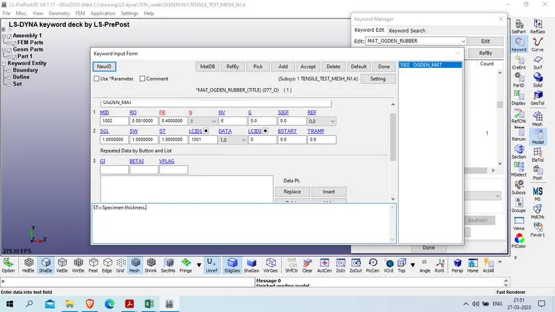
Title : OGDEN_MAT
MID : 1002
DENSITY : 0.0010000 Gm/mm^3
Poission Ratio : 0.4800000
N : 1
SGL:=Specimen gauge length. : 1
SW:=Specimen width. : 1
ST:=Specimen thickness. : 1
LCID : 1001
Result :
Cas1 1 : Hyperelastic_rubber Material
case 1-a where N=1
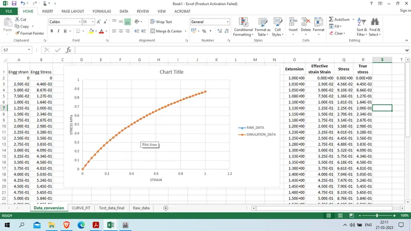
The curve fit perfectly with the raw data
we get mooney constant in d3hsp file which is given below
| N= 1 |
| Mooney constant c1 = 0.1768E+00 |
| Mooney constant c2 = 0.1474E+00 |
now we will use this constant and remove mat_curve from material and put N =0 to check the graph fit
model and part >> keyword manager >> model >> mat>> 077_H-HYPERELSTIC_RUBBER
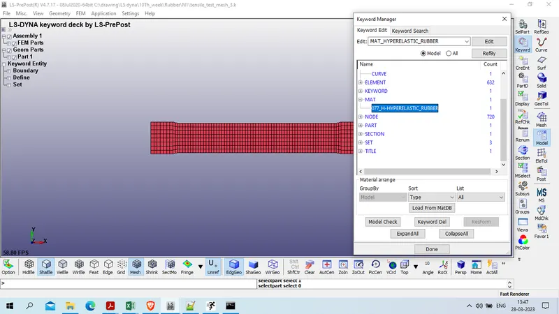
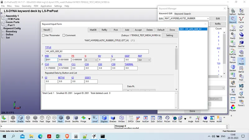
now run the simulation again with above setup
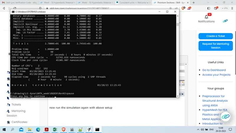
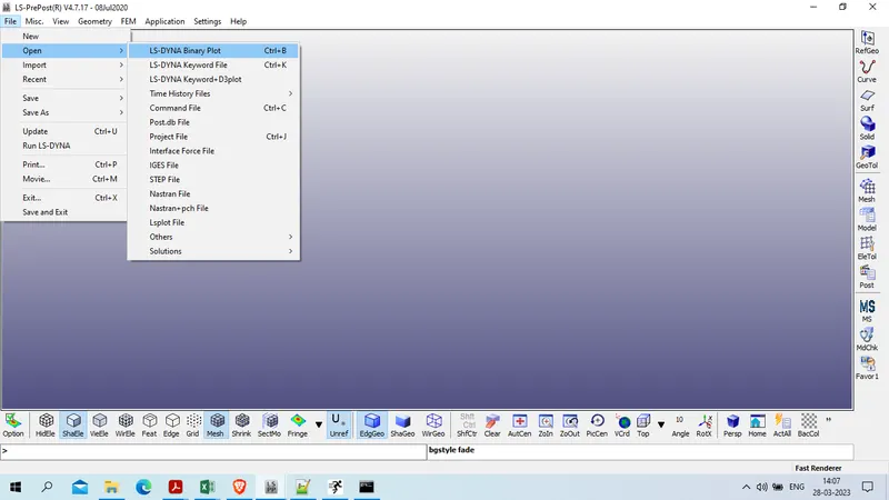
now we will open D3Plot in ls prepost
File >> open >> Open >>Ls dyna Binary Plot
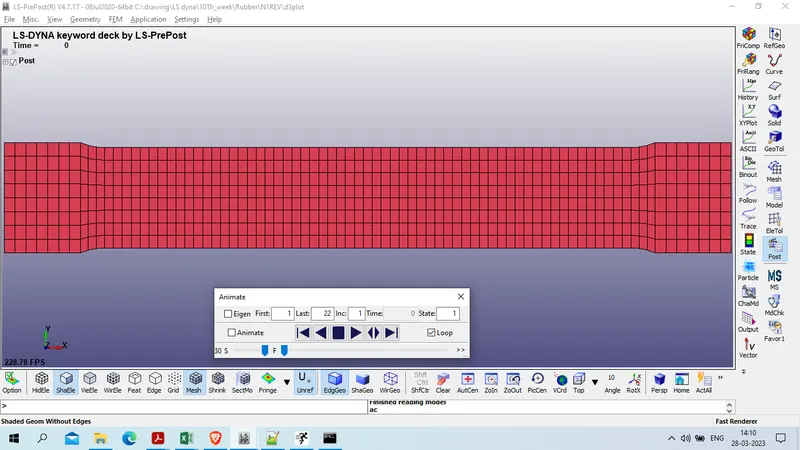
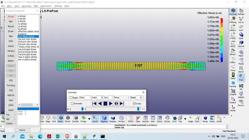
Von Mises stress at center of speciment , element no 327 is as given below
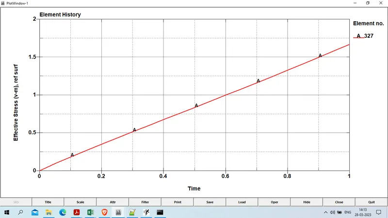
the plot of von mises stress at element no 327 is given as below
similarlly, lower Ipt X strain at element no 327 is given as below
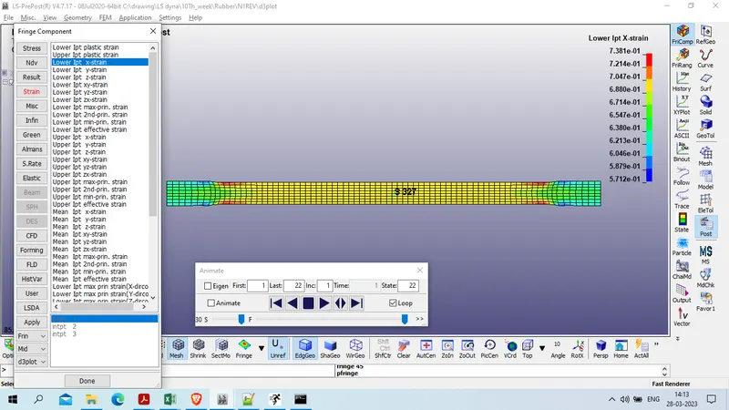
Plot of lower Ipt X strain is given as below
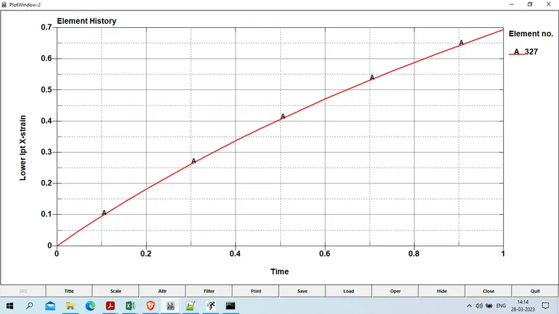
Now we will use these strain and stress value ( from d3hsp) to calculate engineering strain and engineering stress .
Engineering strain = exp(true strain ) -1
and engineering stress = true stress / (1+engineering strain)
using these value of engg strain and stress and input eng strain and stress we will plot the graph and compare the graph as below
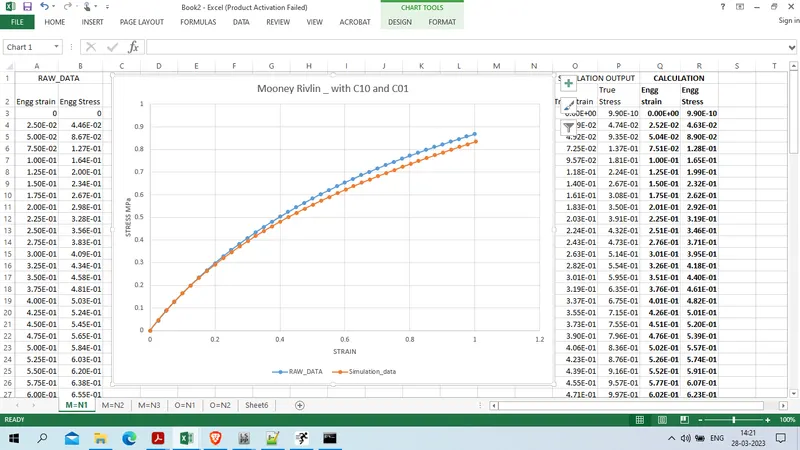
as comapring the simulation data with raw input data we find that output have slighitly deviation from input .
similarlly we will run for N=2 AND N=3 for MOONEY RIVLIN MATERIAL
the constact we recievd as below
| N1 |
| Mooney constant c1 = 0.1768E+00 |
| Mooney constant c2 = 0.1474E+00 |
| N2 |
| Hyperelastic Constant C10= 0.2595E+00 |
| Hyperelastic Constant C01= 0.4594E-01 |
| Hyperelastic Constant C11= -0.2092E-01 |
| Hyperelastic Constant C20= 0.2914E-02 |
| Hyperelastic Constant C02= 0.1016E-02 |
| Hyperelastic Constant C30= 0.0000E+00 |
| N3 |
| Hyperelastic Constant C10= 0.2611E+00 |
| Hyperelastic Constant C01= 0.4420E-01 |
| Hyperelastic Constant C11= -0.6074E-02 |
| Hyperelastic Constant C20= -0.2667E-02 |
| Hyperelastic Constant C02= -0.9968E-02 |
| Hyperelastic Constant C30= 0.1565E-03 |
similarly we will run for simulation using above constant and find out true stress and true strain , using those value we will calculate engg starin and engg stress
the details comparison graph as below
N=2
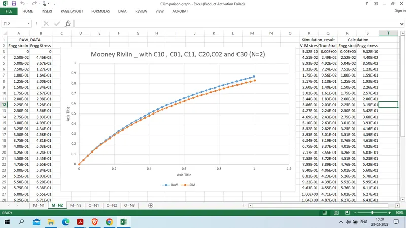
N=3
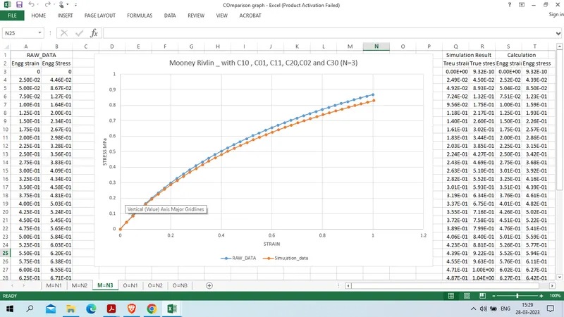
from the all above graph we found similar result for all the case
Now we will use ogden material card instead of Mooney RIVLIN rubber material as we found below constant
| Ogden Material |
| N=1 |
| mu(1)= 9.1076024661337E-01 alpha(1)= 1.3427238801352E+00 |
| N=2 |
| mu(1)= 9.1564732574771E-01 alpha(1)= 1.3399091914039E+00 |
| mu(2)= 2.2259557307116E+00 alpha(2)=-1.8434702588025E-03 |
| N=3 |
| mu(1)=-3.1842578663497E-02 alpha(1)= 1.9263321407459E+00 |
| mu(2)= 2.6137553188494E-01 alpha(2)= 1.5503405391191E+00 |
| mu(3)= 6.8199192354798E-01 alpha(3)= 1.2887820957813E+00 |
now we will use these constant and run sumilation without material curve , so that we will get true stress and true strain which will be calculated as engg strain and engg stress
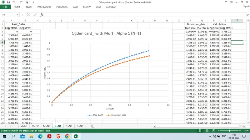
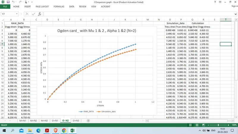
the comparison graph for all 3 cases are given below
N=1
N=2
N=3
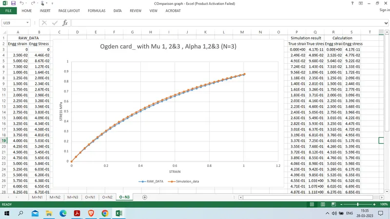
from the above grapg we had found that in case of ogden material in case 3 whew N=3 we fpund curve fit perfectly with the given input data
canclusion :
1. we had created hyperelastic material card for mooney rivlin and ogden material
2. from above we had concluded that in case of ogden where N=3 we had found curve fit closly to input data.