Week 10 Challenge
When a bridge is located in snowy region, besides carrying traffic, it have to tackle snow loads. So alongwith vehicular loads and other loads, snow loads is also being considered for design purpose.
The bridge shown in this challange is facing load of 1250mm setteled snow. Shape is flat ( Bita < 30 degree ) Bridge span is 10m.
Density of setteled snow = 3kN/m`cube`
The depth of accumulation of snow = 1.25m
Snow load So = 3kN/m`cube` X 1.25m X 10m = 37.5kN/m
Shape co efficient from IS 875 part - 4
For flat Bita < 30 degree, m = 0.8
Design snow load S = So X m = 37.5kN/m X 0.8 = 30kN/m
Modelling bridge structure
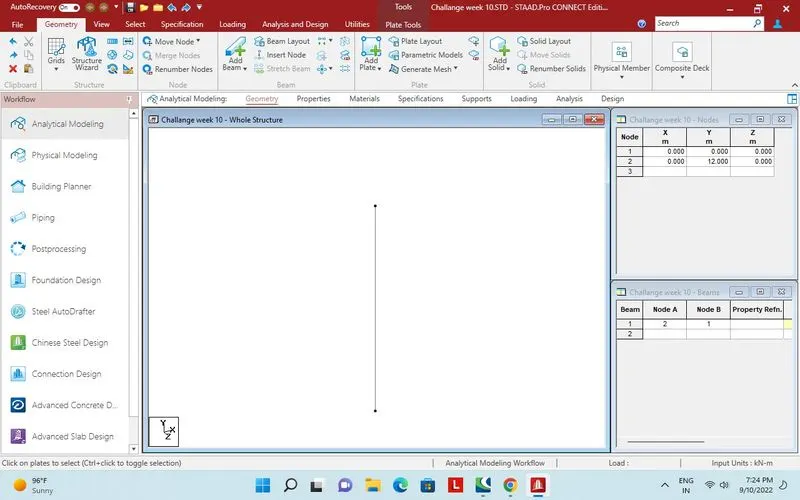
12m beam created in Y direction.
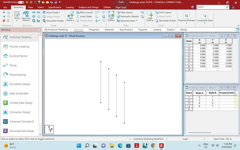
3 identical beam created @ 4m distance in Z direction.
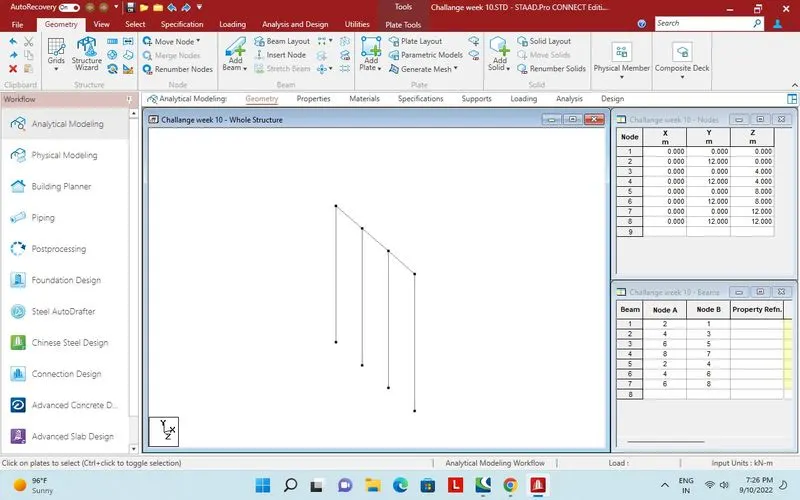
Top node connected by beam.
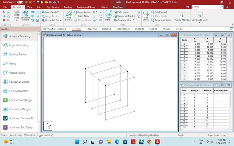
Linked beam created in X direction at a distance of 10m by translational repeat.
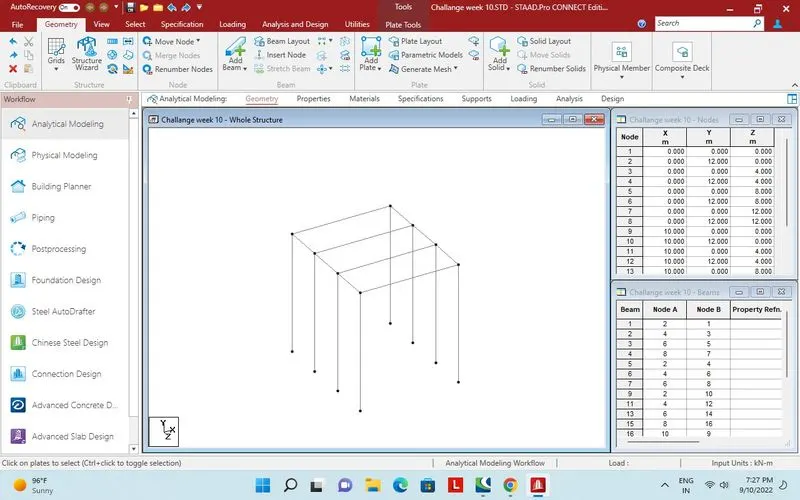
Extra beams deleted.
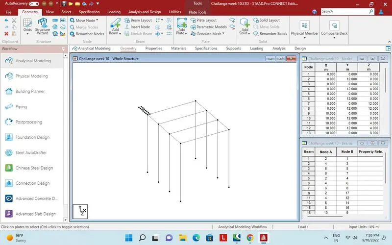
plates of 0.5 X 0.5m created in - Z direction for cantilever portion of deck.
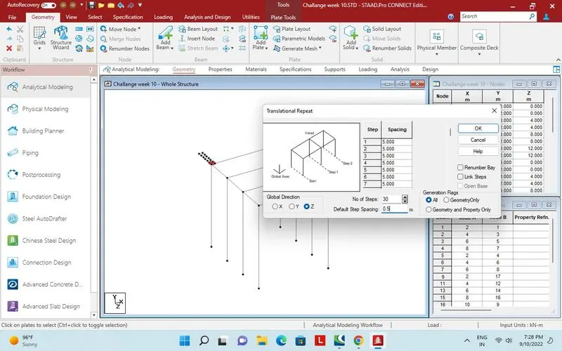
30 more plates creted by translational repeat in + Z direction.
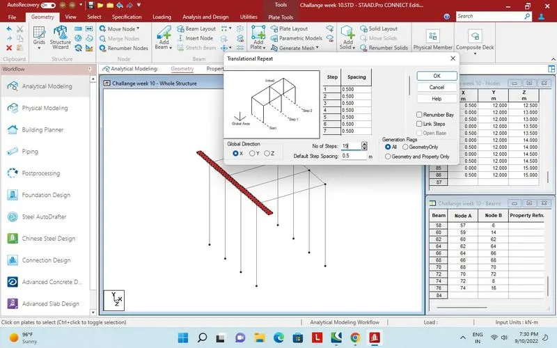
19 sets of plate added in X direction by translational repeat.
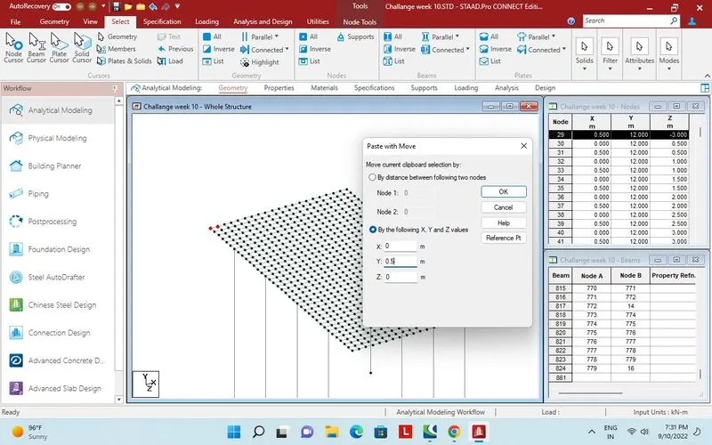
Two nodes copied and paste in Y direction.
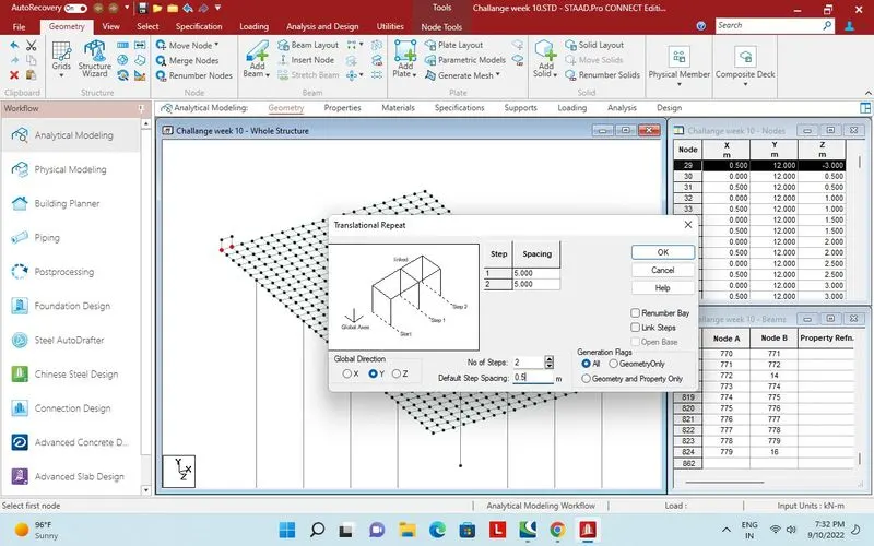
Two more plates added in Y direction by translational repeat
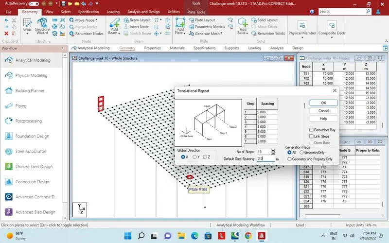
19 set of plates added in X direction.
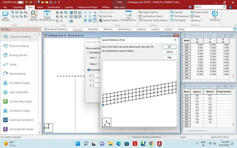
Parapet plates copied to paste in other side.
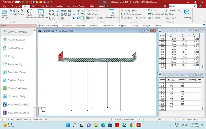
1.5m high parapet in both direction created.
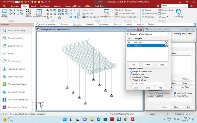
Fixed support assigned.
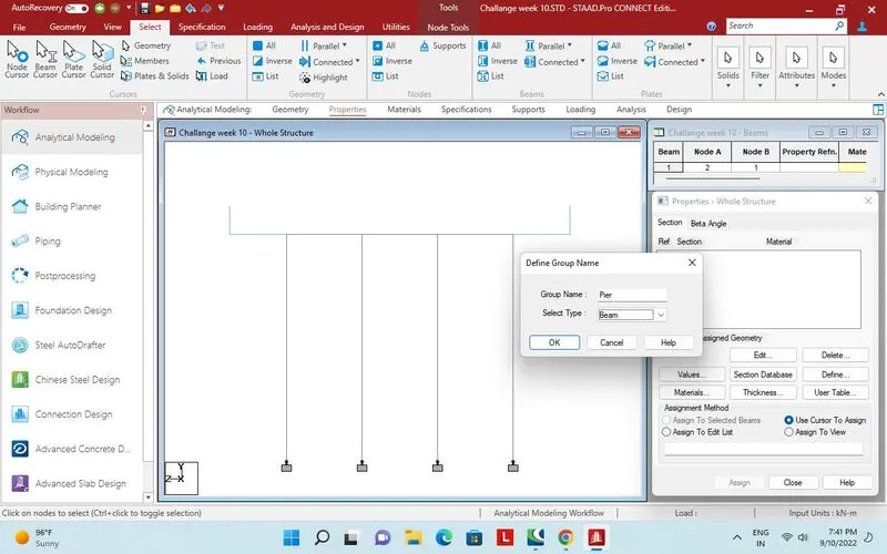
Group created for Pier.
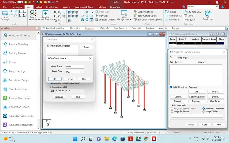
Group for deck plate created.
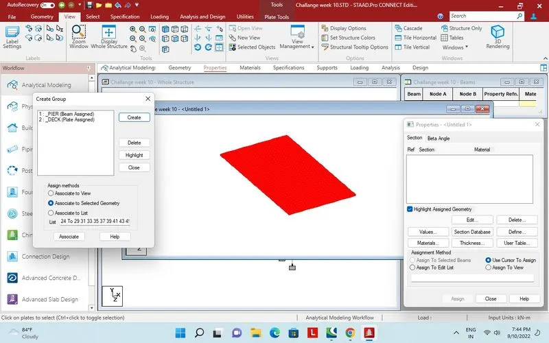
Plates assigned to group deck
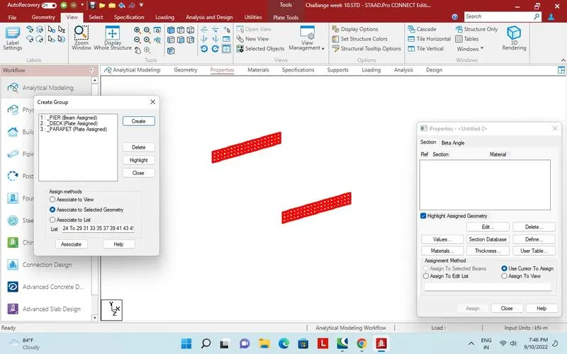
Group for parapet plates assigned.
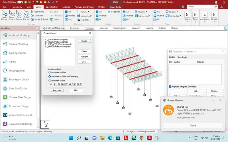 Group of Girder assigned.
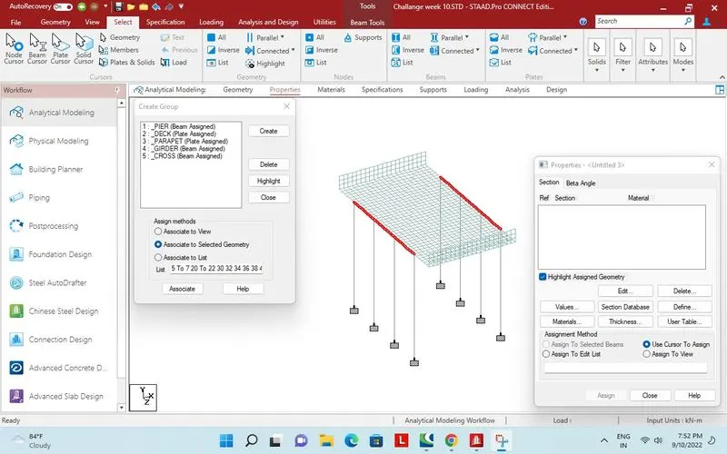 Group for cross beam assigned.
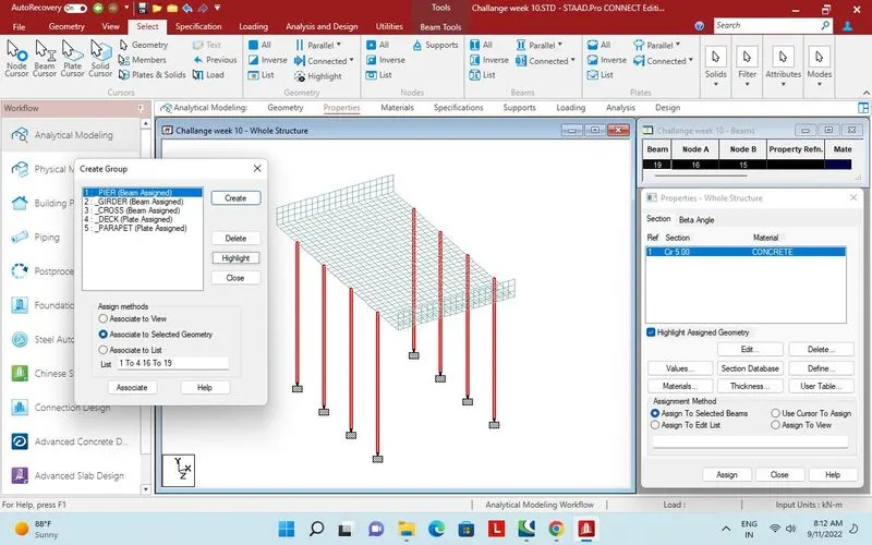 Property assigned to pier
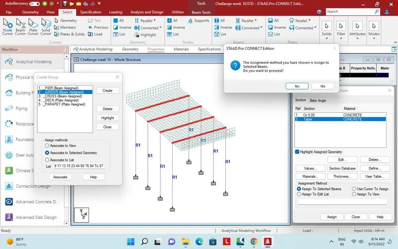 Property assigned to girder.
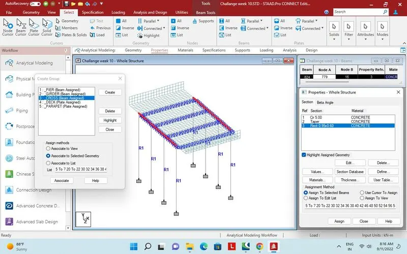 Property assigned to cross beam.
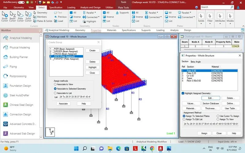
Property assigned to deck plates.
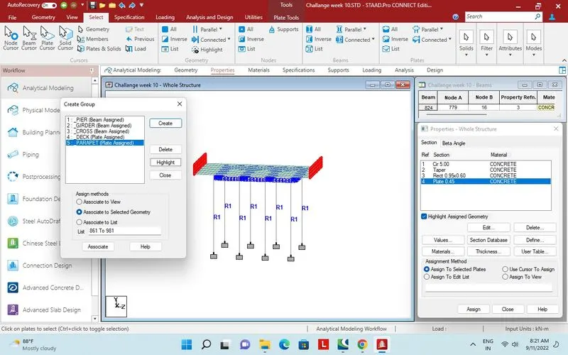 property assigned to Parapet plates.
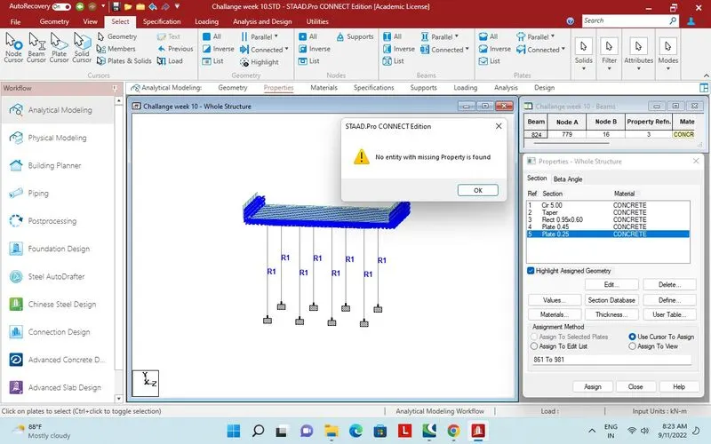
Check for missing property.
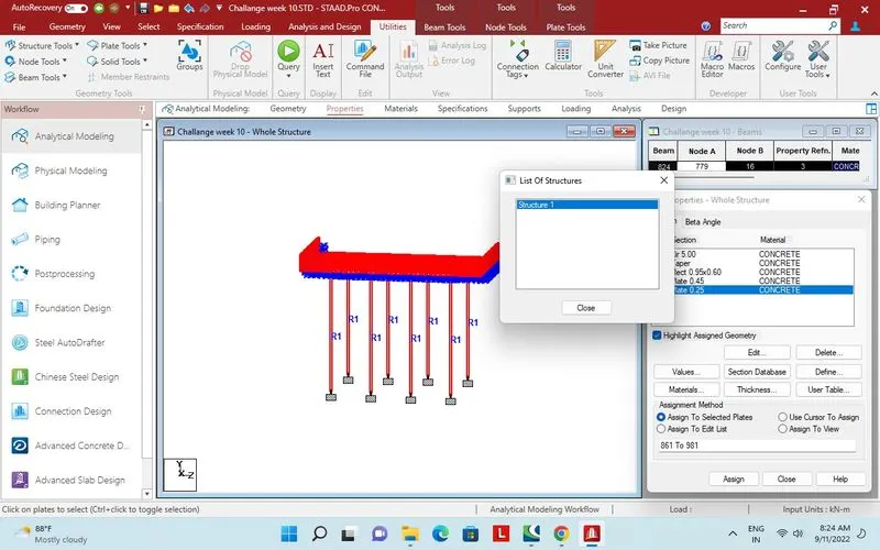
Check for one structure.
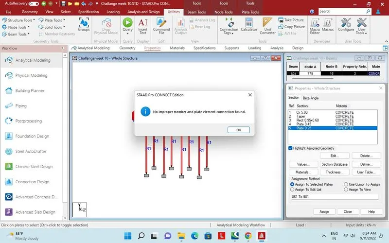
Check for connection.
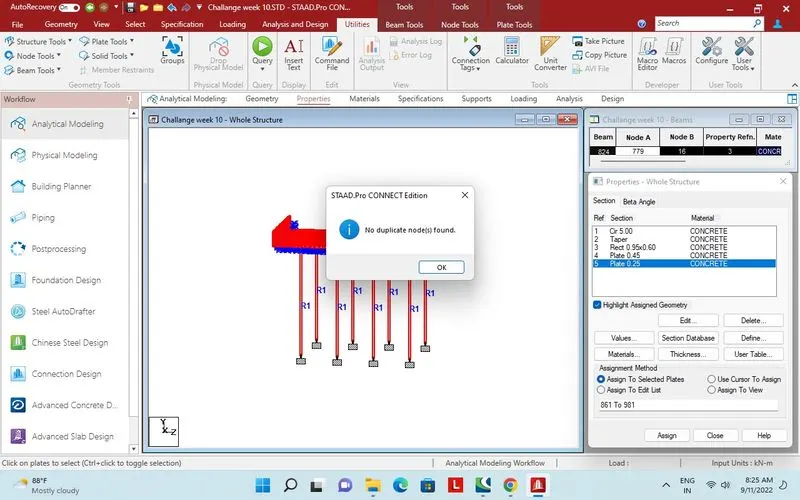
Check for duplicate nodes.
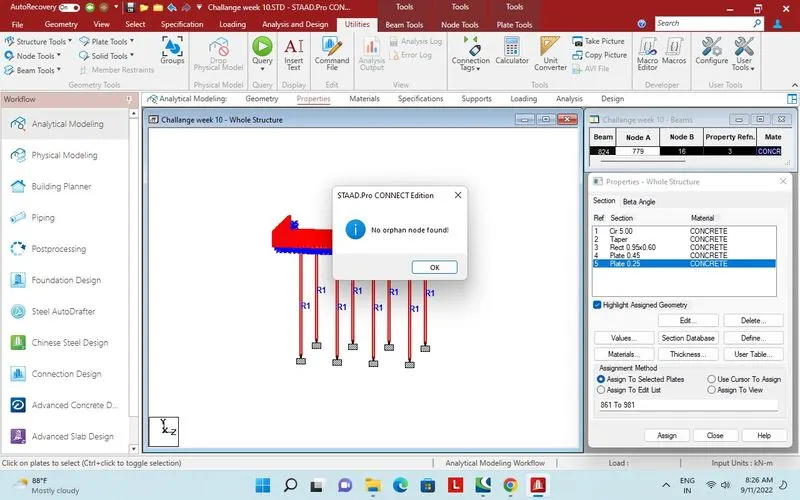 Check for orphan nodes.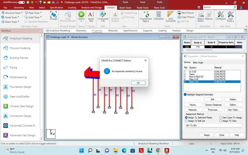
Check forduplicate beam
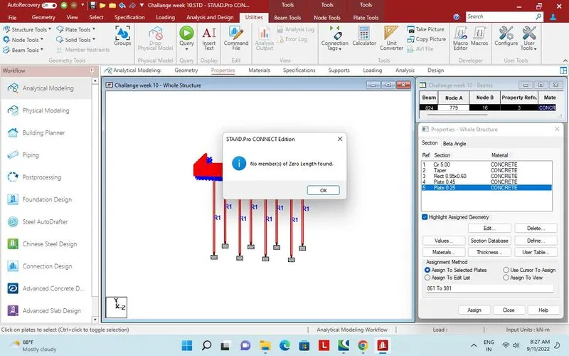
Zero length beam checked
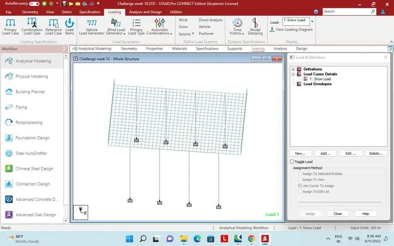
Load case detail, snow load 1st case.
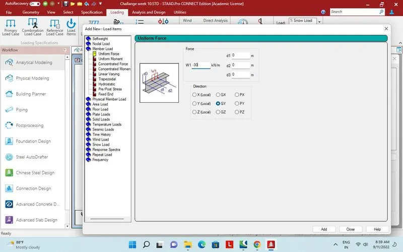
Uniform member load Global y - 30kN/m.
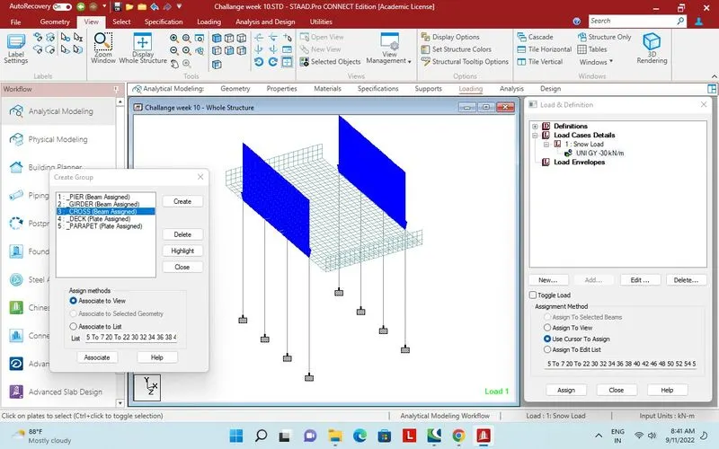
Assigned to cross beam.
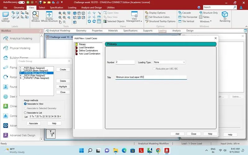
load case 2, Minimum snow load as per IRC.
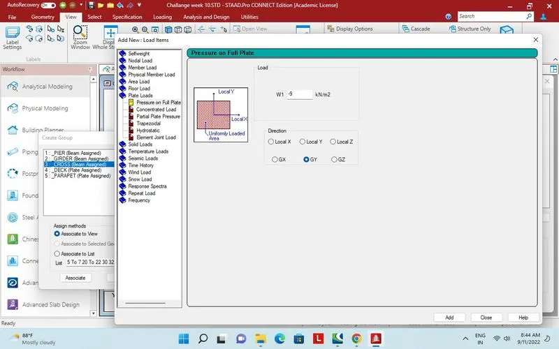
Plate load 9kN/m2
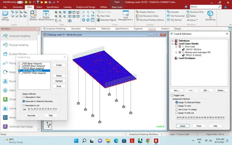
Assigned to deck plates.
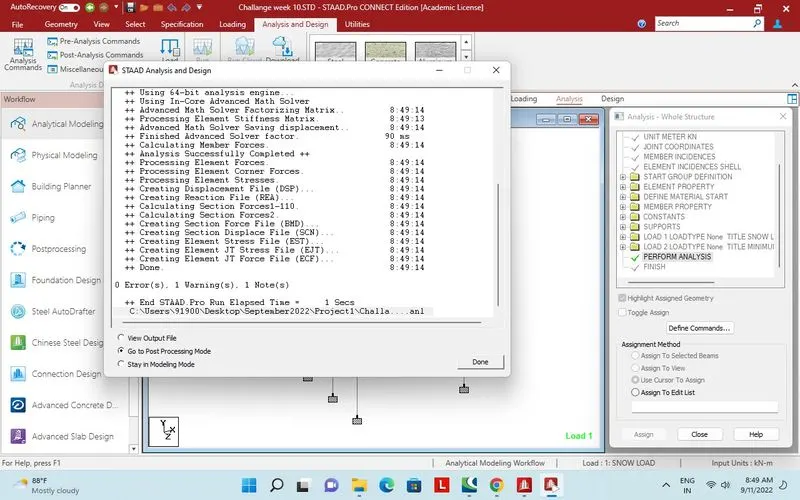
Analysis done.
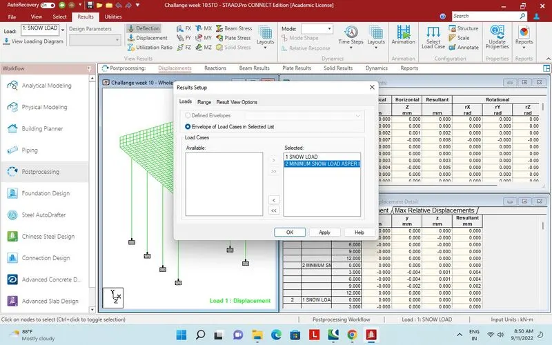
Post processing mode. Two load case.
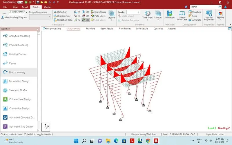
Bending moment whole structure for load case 2.
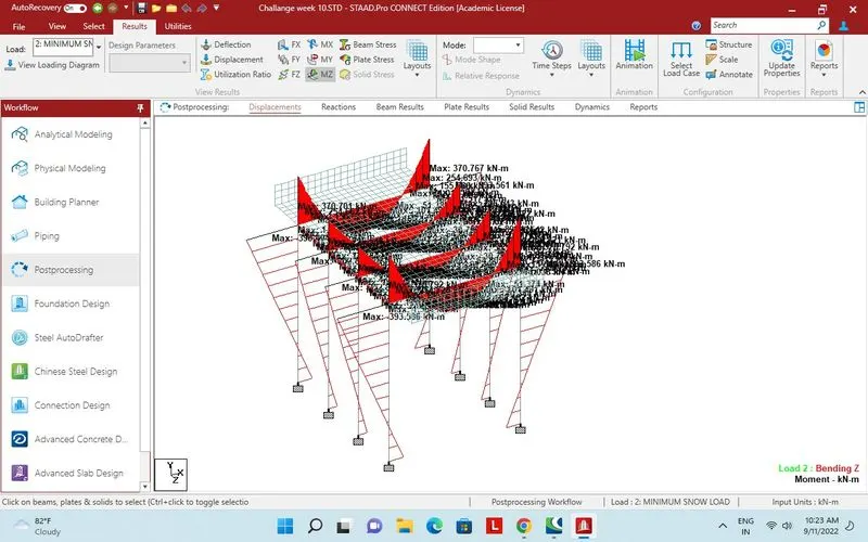
Bending moment about Z axis, load case 2, 393kN maximum.
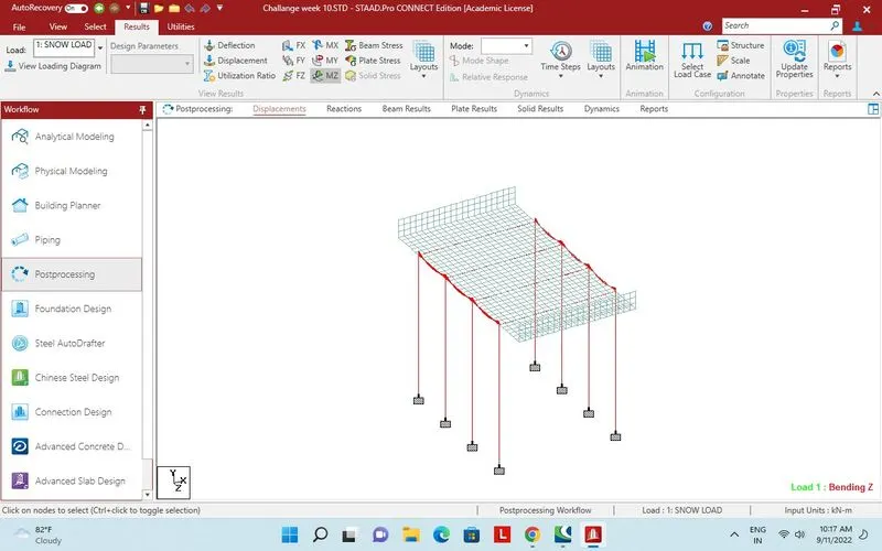
Bending moment MZ for load case 1.
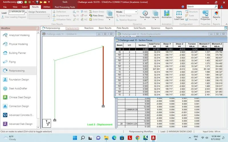
Section force for Pier.
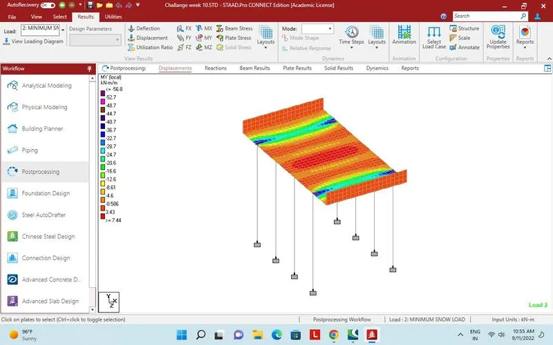
Plate stress, Bending local MY for load case 2.
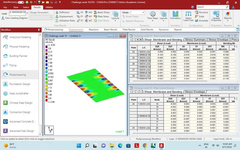 MY local load case 1
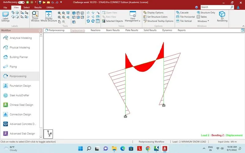
One bay selected for MZ report.
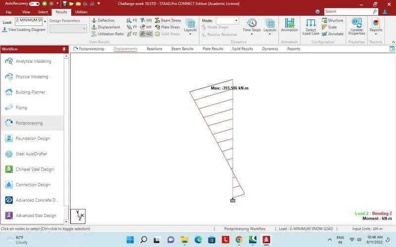
Bending moment maximum in 1Pier.
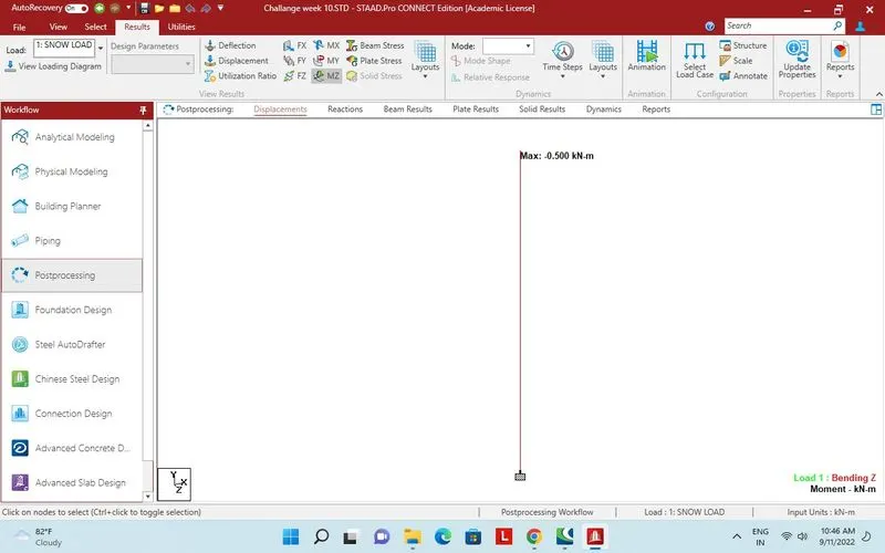
Bending in Pier For load case 1.
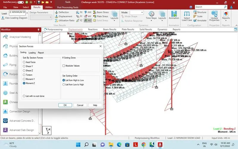
Section force on beam MZ max.