Week 10 Challenge
Aim and Introduction :-
- The aim of this challenge is to define all checks need to be followed in design of well foundation regarding the stability and the design.
- To list out all the necessary clauses from IRC codes applicable.
- Again to define all the type of limits in ULS and SLS for design of a RCC component. Define the limit states and the factors in it as per IRC 112.Also mention shear checks and the difference in shear with/without reinforcement.
- To check steining thickness and its steel and also the change in PCC and RCC steining.
- To describe the detail of spacing of 6 pile group system and bulb theory with stress distribution.
1)What all checks need to be followed in design of well foundation regarding the stability and the design. List out all the necessary clauses from IRC codes applicable.What are the limits in ULS and SLS for design of a RCC component. Define the limit states and the factors in it as per IRC 112. Also mention shear checks . what is the difference in shear with/without reinforcement?
Ans: Foundations supporting the superstructure located in deep water cannels shall comprise of properly dimensioned caissons preferably having a single dredge hole. While selecting the shapes, size and type of well, the size of abutment and pier to be accommodated , need for effiecting streamline flow the possibility of use of pneumatic sinking,the anticipated depth of foundation and the nature of data to be penetrated should be kept in view.
Diffrent Checks needs to be checked for Stability -
- Allowable/Diffrential Settelment- The calculated differential settlement between the foundations of simply supported spans shall not exceed 1 in 400 of the distance between the two foundations from the consideration of tolerable riding quality unless provision has been made for rectification of this settlement. As per clause no. 706.3.2, IRC -78,2014
- Tension at the base of foundation- In case of rock if tension is found to be developed at the base of foundation, the base area should be reduced to a size where no tension will occur and base pressure is recalculated. The maximum pressure on such reduced area should not exceed allowable bearing pressure. Such reduced area shall not be less than 67 percent of the total area for load combination including seismic, or impact of barge, and 80 percent for other load combinations. As per clause no. 706.3.3, IRC -78,2014
- Base Pressure- For well foundation resting on soil the allowable bearing pressure on ultimate bearing capacity may be taken as 2.5 for soil.As per clause no. 706.3.1.1.1, IRC -78,2014
Design Considerations AS per clause no. 708.3
- The external diameter of the brick masonary wells shall not exceed 6m. Brick masonary wells for depth greater than 20m shall not be permitted.
- For brick masonary wells , brick not less than Grade - A having strength not less than 7MPa conforming to lS 1077 shall,be used in cement mortar not leaner than 1 :3.
- For plain concrete wells, vertical reinforcements (whether mild steel or deformed bars) in the steining shall not be less than 0.12 percent of gross sectional area of the actual thickness provided. This shall be equally distributed on both faces of the steining. The vertical reinforcements shall be tied up with noop steel not less than 0.04 percent of the volume per unit length of the steining.
- In case where the well steining is designed as a reinforced concrete element, it shall be considered as a column section subjected to combined axial load and bending. However, the amount of vertical reinforcement provided in the steining shall not be less than 0.2 percent (for either mild steel or deformed bars) of the actual gross sectional area of the steining. On the inner face, a minimum of 0.06 percent (of gross area) steel shall be provided. The transverse reinforcement in the steining shall be provided in accordance with the provisions for a column but in no case shall be less than 0.04 percent of the volume per unit length of the steining.
Design Check
-
Stability of Well Foundations
-
The stability and design of well foundations shall be done under the most critical combination of loads and forces as per Clause 706. The pressure on foundations shall satisfy the provisions of Clause 706.
- For stability check generally two methods has been followed
- 1)Terzaghi's method
- 2)IRC method
-
The side earth resistance may be calculated as per IRC-78. The use of provisions IRC:45 may be used for pier well foundations in cohesionless soil.The side earth resistance shall be gnored in case of well foundations restingon rock. If rock strata is such that the allowable bearing pressure Is less than 1.MP4, then the side earth resistance may be taken into account.
-
If the abutments are designed to retain earth and not spilling in front, the foundations of such abutments shall be designed to withstand the earth pressure and horizontal forces for the condition of scour depth in front of 1.27 d with approach retained and 2 d with scour all around. In case of scour all around live load may not be considered. As per clause no 708.4.3.1.IRC 78-2014
-
At Construction stage stability check also needed.At time of sinking tilts and shift may arrise. As far as possible the wells shall be sunk plumb without any tilts and shifts. However a tilt of 1 in 80 and a shift of 150mm due to translation (both additive )in a direction which will cause most severe effect Shall be considered in the design. As per clause 708.5, IRC 78.
-
Limits in ULS for design of a RCC component:-
- The ultimate limit state is the design for the safety of a structure and its uses by limiting the stress that materials experience. In order to comply with engineering demands for strength and stability under design loads, ULS must be fulfilled as an established condition.
- The ULS is a purely elastic condition, usually located at the upper part of its elastic zone (approximately 15% lower than the elastic limit). This is in contrast to the ultimate state (US) which involves excessive deformations approaching structural collapse, and is located deeply within the plastic zone.
- If all factored bending, shear and tensile or compressive stresses are below the calculated resistances then a structure will satisfy the ULS criterion.
- Ulimate limit state ULS, the limit state of equilibrium when subjected to various design combinations of ultimate loads the bridge or any its components considered as a rigid body shall not became unstable, So this is the one equilibrium as awhole it should be equilibrium position. And limit state of strength the bridge or any of its components shall not lose its capacity to sustain the various ultimate load combinations by excessive deformation , transformation into the mechanism, rupture , curshing or buckling.So that is the one we can consider that as a part of the limit state of strength .The next one is called under ulimate limit states , so the limit state of equlibrium that is we are not going to internal stresses that from externally whether it is in stable condition or not equilibrium condition then limits state of strength we are considering that one the stresses.
Limits In SLS for design
-
The Serviceability Limit State (SLS) is defined as the state of design beyond which a structural system loses operationally its serviceability for the actual service load that the structure is subjected to.
-
It is the internal stresses developed in the materials of structural elements shall not exceed the specified magnitudes when subjected to the combinnation of serviceability designations.
Shear Check :-A shear test is designed to apply stress to a test sample so that it experiences a sliding failure along a plane that is parallel to the forces applied. The most common use of a shear test is to determine the shear strength, which is the maximum shear stress that the material can withstand before failure occurs, of a material.
Difference in Shear with/Without reinforcement:-
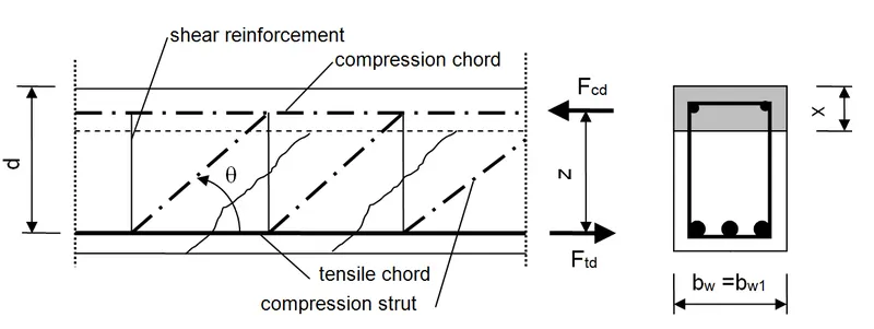
- Shear reinforcement is required to prevent development diagonal cracks. The diagonal tension cracks develop in the beam, when the strength of the beam in diagonal tension is less than the strength in flexural tension. On this type of failure, the cracks start to develop due to the flexure at mid-span.
- But the structure without shear reinforcement is viable to crack easily at the high tension zone where the diagonal crack arises due to shear.
Steining:-
Steining is a wall or shall type of structure made up of RCC, and which helps to transfer the load to the curb. It serves as an enclosure for excavating the soil for the penetration of the foundation well.
Thickness of steining
According to the clause 708.2.3.1 of IRC:78-2014 [2]the steining thickness will be given by the formula:
- Steining is a wall or shall type of structure made up of RCC, and which helps to transfer the load to the curb. It serves as an enclosure for excavating the soil for the penetration of the foundation well.which is not such flexible in case of PCC type.
Spacing and Tolerances for Pile as per IS2911:-
The pile shall not vary from the planned location by more than 100 mm (4 inches). For abutments, this tolerance is 25 mm (1 inch). Also, piles may not have more than a 20 mm per meter (1/4 inch per foot) variation at their tip from the vertical or batter.
- The spacing of piles is basically taken as 3 times the dia of pile to avoid overlapping of the pressure bulb created by indivisual pile.
- For vertical driven or bored cast-in-situ piles an angular deviation of 1.5 percent and for raker piles an angular deviation of 4.0 percent should not usually be exceeded except exceptional cases.
- Foundation piles should not deviate more than 75.00 mm or 1/6 times of its diameter whichever is less and for piles having more than 600mm diameter deviation should be 75.00mm or 1/10 times of its diameter whichever is higher from their designed coordinates at the operational level of the piling rig/platform.
- In case of a single pile in a column, positional tolerance should not be more than 50 mm or 1/6 times of its diameter whichever is less and for piles having more than 600mm diameter deviation should be maximum of 100mm.
- In some exceptional cases, greater tolerance may be prescribed for marine piles/driven over water and for raking piles.
Beyond the above tolerances for pile and to such an extent that the resultant eccentricity of applied load cannot be taken care of by the redesign of pile cap or pile ties, the Foundation piles must be replaced or extended by one or more additional piles.
Pressure Bulb Theory:-
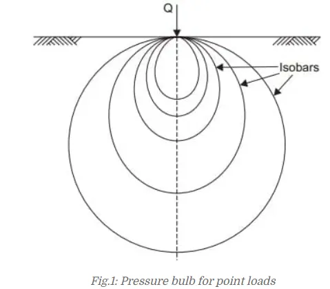
- Pressure bulb is the area to which apllied load can affect or in other words the area to the stresses(pressure) are developed in the vertical direction due application of load on the soil. Isobar is the line where all the points on the line are subjected to same pressure(stresses).
- An isobar or pressure bulb is a stress contour or a line which connects all points below the ground surface at which the vertical pressure is the same in fact, an isobar is a spatial curved surface and resembles a bulb in shape, this is be cause the vertical pressure at all points in a horizontal plane at equal radial distances from the load is the same. Thus the stress isobar is also called the "bulb of pressure" or "pressure bulb".
- An isobar diagram, consisting of a system of isobars shown below.
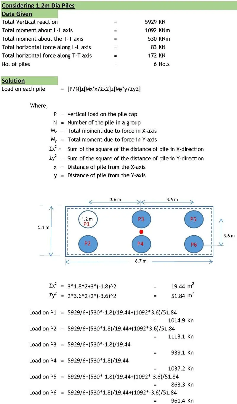
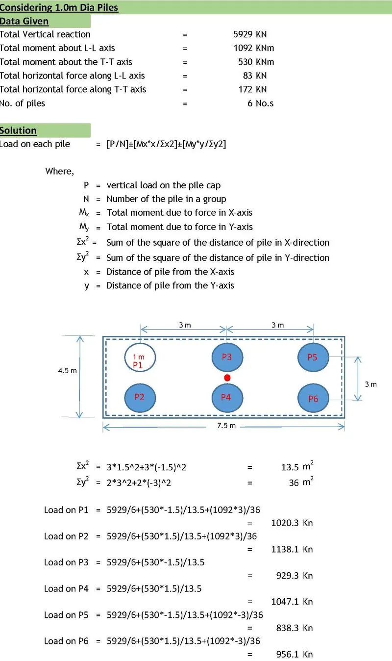
2.To Calculate the reaction exerted on the group of piles from the pier of the bridge.
Solution:
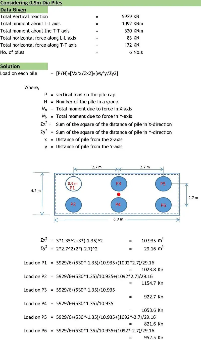
Vertical Capacity of Pile
For 1.2 m dia pile = 2000 Kn
For 1.0 m dia pile = 1750 Kn
For 0.9 m Dia Pile = 1500 Kn
So 6 No.s of 0.9m dia pile has been recommended.