Week 10 Challenge
Aim and Introduction:-
- The aim of this challenge is to determine the forces on the structure due to application of snow load and to calculate the effect of the snow load on the structure as various forces like shear force, bending moment etc using staad Pro.
- So first of all the details components for calculating the snow load as per the given data is to be determined.
- Then the model will be created in Staad pro., snow load is applied on the the structure as different load cases and the reactions, stresses and bending moments due to the loading is being analyzed for the structure as given.
Data Given:-
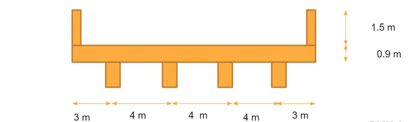
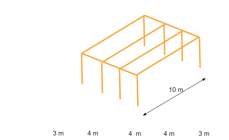
- Span of bridge - 10m
- Width of Bridge - 18m
- The bridge is subjected to snow load - Setteled Snow
- β < 30 degree
- Depth of accumulation of snow - 1250mm
Calculation of the Snow Load :-
Case -1
Density of Setteled Snow = ρ = 3 KN/m^3
Depth of snow = 1.25 m
Flat deck, β = 0'
i.e., μ =0.8
Snow Load= So = 3 x 1.25 x 10
= 37.5 KN/m
Design Snow Load = S = μ x So
= 0.8 x 37.5
= 30 KN/m
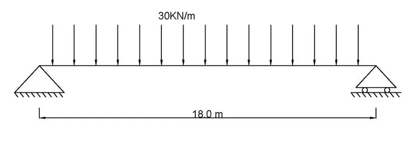
- Also the minimum load on the super structure for snow load as 9 KN/m^3 has to be applied on the structure.
Calculation of the Parapet wall load:-
Considering the parapet wall of RCC wall with 200mm thick
Load due to parapet wall = thickness of parapet wall x ht. of parapet x Density of conc.
= 0.2 x 1.5 x 25
= 7.5 KN/m
STAAD Pro. Analysis:-
- The bridge has been created by considering 1 spans of 10 m length and the cross section of the bridge is taken as 18 m carriage way width.
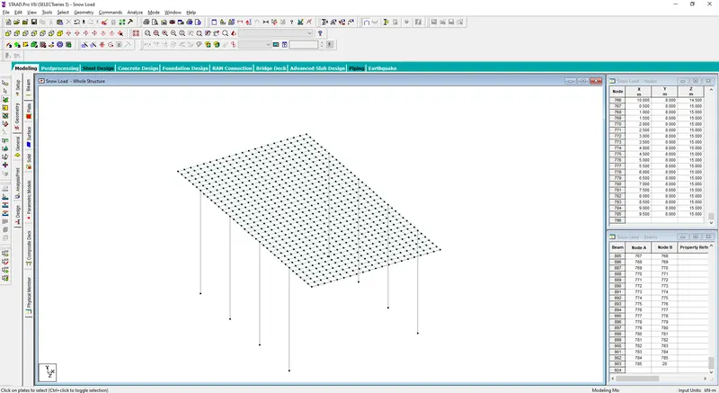
The bridge model has been created by considering the following details.
- Pier - 1.2m x 1.2m
- pier Ht. - 8.0m
- Main girder - 0.75m x 1.2m
- cross girder - 0.75m x 0.75m
- Deck slab (Plate) thickness - 0.90m
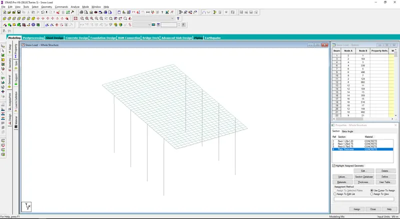
Propoerty has been defined as per the given data.
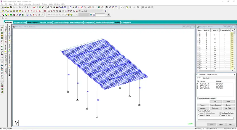
Properties has been assigned as per the defined dimensions.
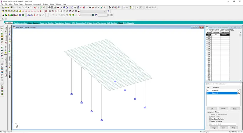
Fixed support has been assigned to the structure.
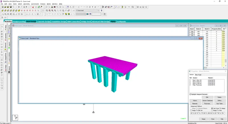
The 3D render view of the defined structure.
Load & Definations:-
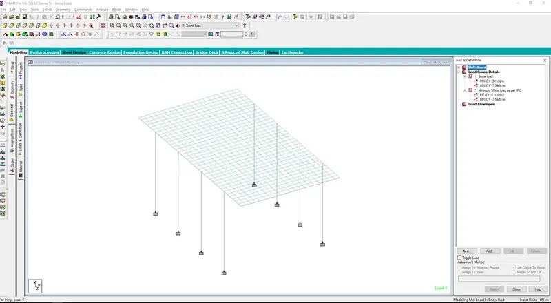
- Two load case details has been defined. The first defined load case is as per the calculations from the given data and the second case is as per the minimum snow load consideration. The load for the parapet wall has been defined as per calculation in both the cases of snow load.
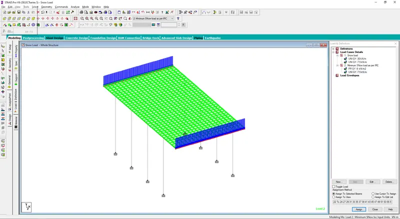
- All the loads has been assigned to the structure.
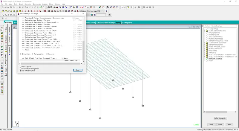
- Then the structure is being analyzed and results as 0 error with 0 warning.
RESULTS:-
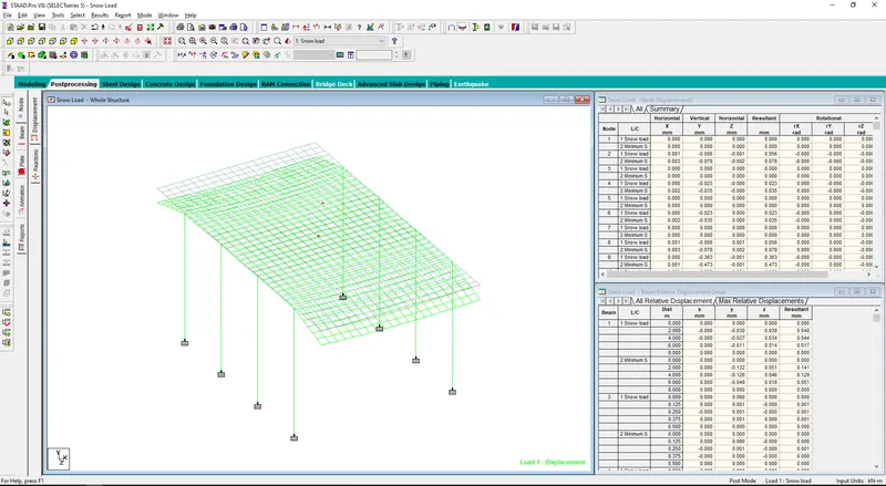
- Deflection due to defined load case 1.
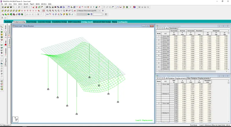
- Deflection due to defined load case 2.
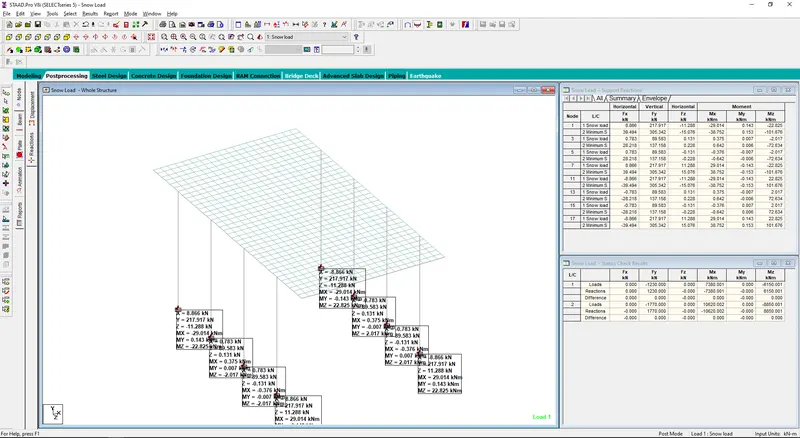
- Reactions at the foundations due to defined load case 1.
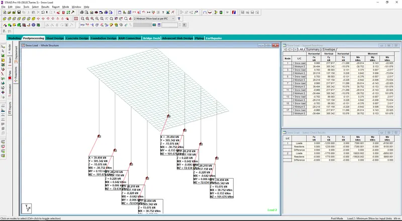
- Reactions at the foundations due to defined load case 2.
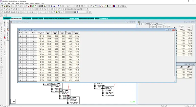
The maximum end forces has been determined from reports and it can be seen that the maximum resultant force coming due to load case 2.
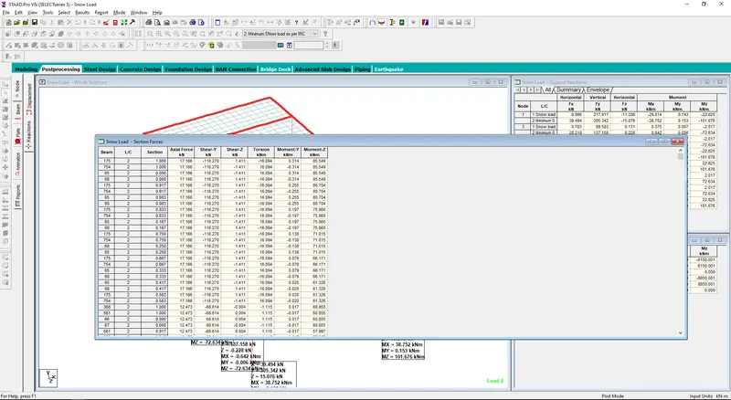
In this case also the maximum load coming due to load case 2. so it can be concluded that in this case load case 2 i.e. the minimum snow load as per IRC has been governing.
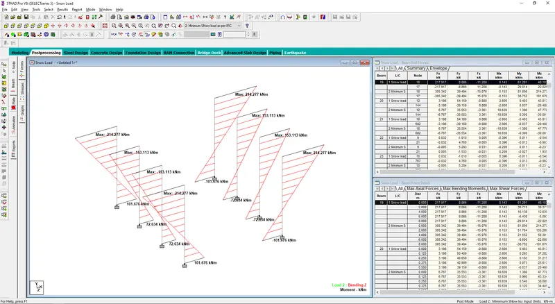
- Maximum value of Mz for the piers at ends has been annotated.
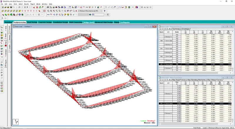
Mamimum value of Mz at mid points for the girders.
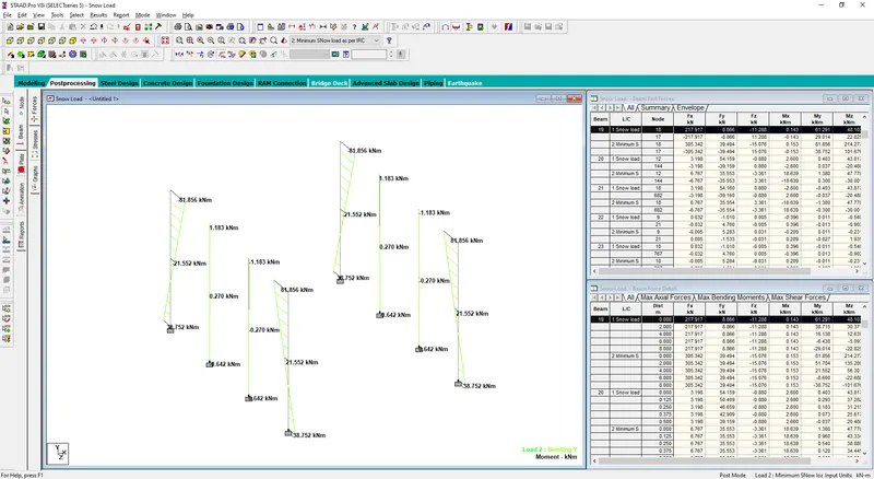
- Value of My for the piers with value of the moment.
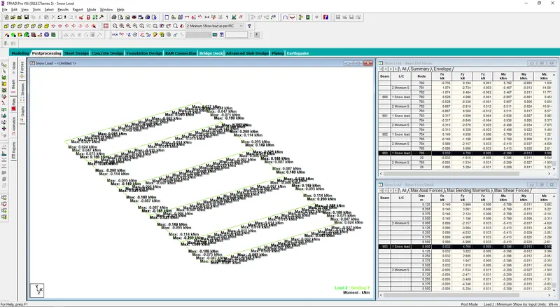
- Value of My for the gorders with value of the moment.
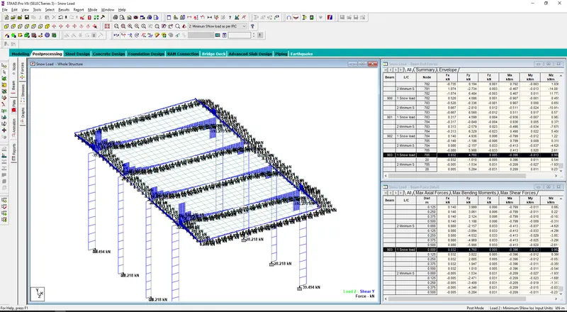
- Value of Fy for the all the beam of concerned load case.
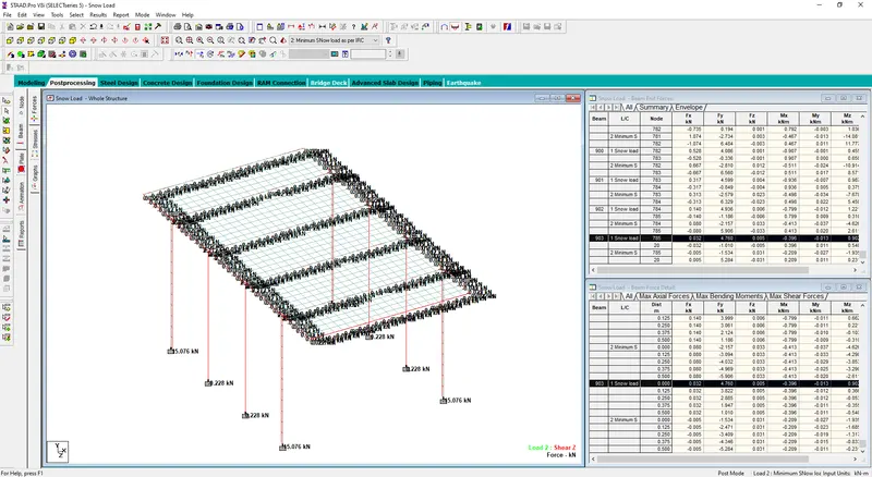
- Value of Fz for the all the beam of concerned load case.
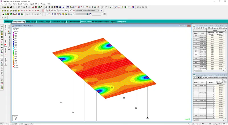
- The stress variation in the plates of the deck slab of the structure in My for the loading of load case 2.
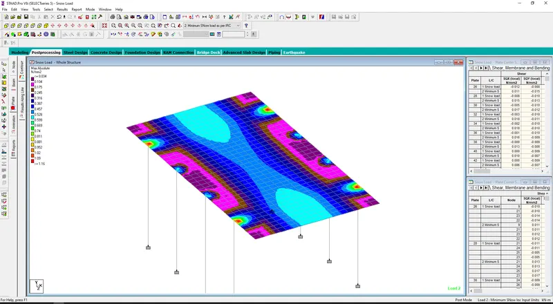
Maximum absolute stress variation of the same load case.