Week 10 Challenge
Q-1. Purlin & Girts number determination problem
AIMS & INTRODUCTION:
Total number of purlins and girts are required to be calculated-
Inputs for given building :
Rafter span = 50 m
Bay spacing = 8 m
Roof slope = 1 in 10
Height of column = 12 m
Brick wall height = 2 m
Purlin spacing = 1.2 m
Girt spacing = 1.5 m
PROCEDURE IN DETAILS-
In the print screen of the model various given data have been indicated on the basis of which manual solution of the challenge has been initiated and should not be treated for calculating no of Purlins & Girt.
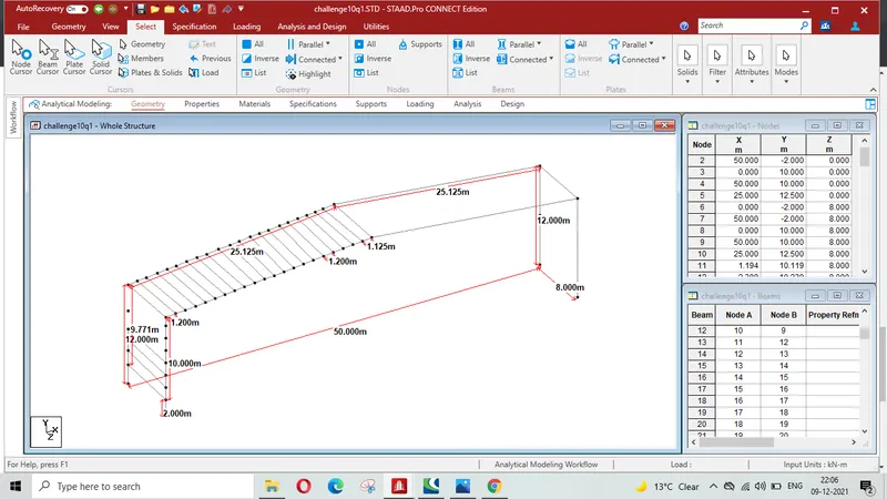
Calculation of numbers of purlins-
Half of the span of Rafter = 50/2= 25 m
Height of the Truss= 2.5 m ( As per slope 1 in 10)
Inclined length of Rafter `
Length of Rafter :
`sqrt(25^2+2.5^2)` = 25.124`m
Number of purlins = ( Inclined length of rafter/spacing of purlins) +1
= (25.124/1.2)+1 = 20.936 +1 = 22
Total purlins on entire span of Truss = 22x2 = 44
Calculation of numbers od Girts-
Bay length = 8 m ( This data is not required for the solution of given problem)
Column height = 12 m
Brick height = 2 m where no Girts are not required to be installed
Remaining height of columns for grit installation = 12 - 2 = 10 m
Girt spacing = 1.5 m
Number of Girts on one side =( 10/1.5) +1= 8
Total nos of Girts on both side = 8x2 =16
RESULT -It is concluded that As per above calculation Total nos of Purlins on both side of slope are 44 and total nos of Grit on both side are 16.
Q-2. Taper the beam according to BMD envelope
AIMS & INTRODUCTION:
For the STAAD file attached and for given loading taper the beam for the BMD envelope and check utility ratio within limit.
Given Data :
- Staad file of the model
- Loading
- Design parameters assigned to the members
PROCEDURE IN DETAILS
From the attached file file of the model following utilization factor of various members as indicated in the table given below are found in the post processing commamd after analysing the the structure . Print screen of model indicating utilization factors is also attached.
| Member Name | Utilility Ratio | Remark |
| Left column | 0.634 |
Need to be optimize as only 63.4% of its capcity has been utilized for critical loading |
|
Right column |
0.598 |
Need to be optimize as only 59.8% of its capcity has been utilized for critical loading |
| Middle column | 0.863 | In this column no moment is to be transferred as moment is released so its capacity can be utilized further upto 100% as in future this member is not supposed to carry moment |
| Left Beam | 0.866 | Need to be optimize as only 86.6% of its capcity has been utilized for critical loading |
| Right Beam | 0.866 | Need to be optimize as only 86.6% of its capcity has been utilized for critical loading |
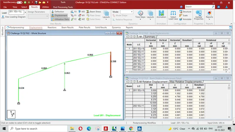
Section of various members have been optimized using Taper section as per Bending Moment diagram to such an extent that all the members are utilized more than 90%. Print Screen after optimization of design is also attached below-
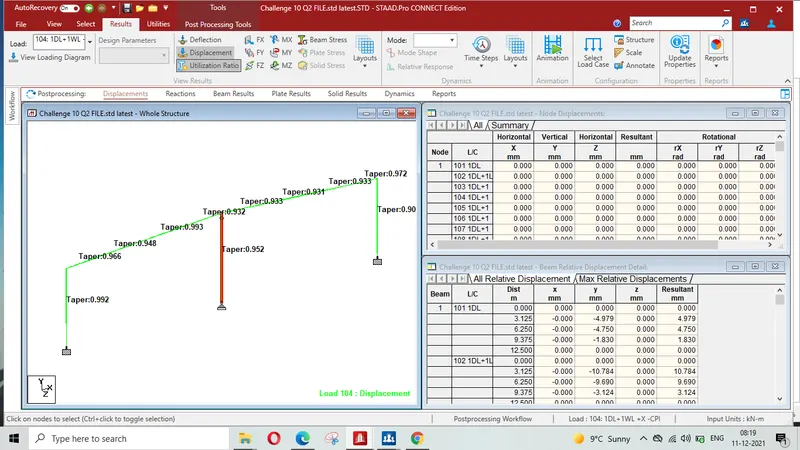
Print Screen of BMD and utility Ratio after optimizatio is given below-
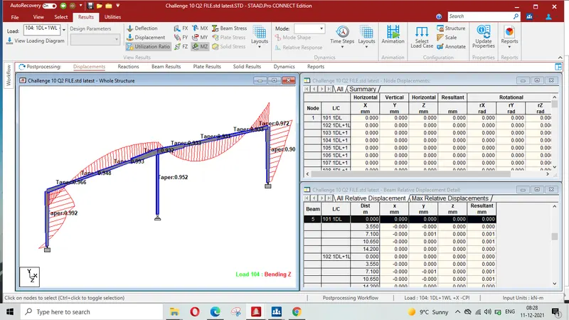
3D Rendering view of the Model after optimization of sections is given below-
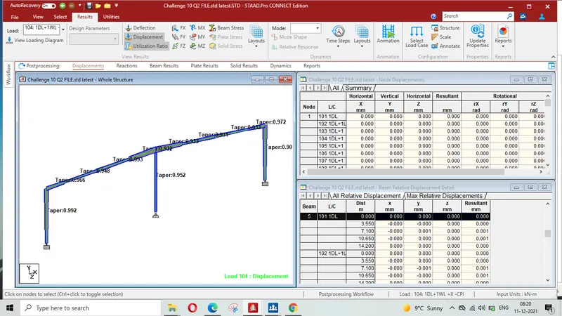
RESULT : As per challenge Beams have been tapered as pe BMD envelop and utility ratio of various members have been checked and are with in limit . Staad file after tapering the beams is attached.
Q3. Determining Wind load for certain category and condition as per IS 875 Part 3 :2015
AIMS & INTRODUCTION:
Wind pressure on the wall of given Industrial Building is to be calculated.
Given data-
Dimension of Building = 10 m x 5 m
Height =6m
Bay spacing = 2.5 m
Wall opening = 15%
Building is situated in Chennai
Assuming - 1) Terrain Category 3
2) Design life of the structure 50 years
3) Topography : Plane woth upwind slope `theta` < `3^0`
Roof Angle = `5^0`
PROCEDURE IN DETAILS
Model with given data has been prepared as given below-
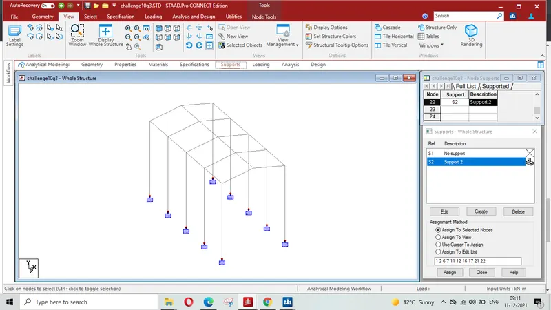
Basic wind speed `V_b`= 50 m/s ( For Chennai as per IS 475 part-3 , Appendix A , clause 5.2 )
STEP-1:
Design wind speed `V_z= V_bxxK_1xxK_2xxK_3xxK_4`
where K1 = Risk/Probability factor ( IS 875 Part-III, Page-11, Table-1)
Considering general building and structure and `V_b`=50 m/s
K1= 1 from Table 1 clause 5.3.1 for design life of structue 50 years & and for given Basic wind speed of 50 m/s
K2 = Terrain height & height factor ( IS 875 Part-III, Page-12, Table-2) =0.91
K3 = Topography factor = 1.0 ( Assuming upwind slope < `3^0`) (clause 5.3.3)
K4 = Imporance factor for cyclonic region =1.15 Assuming Industrial structure ( clause 5.3.4)
Therefore Vz = 1x0.91x1x1.15x50 =52.33 m/s
STEP-2 :
Wind pressur Pz = 0.6 `(V_z)^2`
where `P_z` = wind pressure in N/`m^2` at height z
Therefore `P_z`= 0.6x`(52.33)^2`= 1643.06 N/ `m^2`= 1.64 KN/`m^2`
STEP-3:
Design wind pressure `P_d = K_d xxK_axxK_cxxP_z`
where `K_d` = wind directionality factor 1.0 for cyclone affected region
`K_a`= Area averaging factor =0.9 for tributary area < `25m^2`
(Tributary area = 6x2.5 = 15 m^2)
K_c= combination factor =0.8
Therefore P_d = 1x0.9x0.8x1.64 = 1.181 KN/`m^2`
STEP-4 :
Wind load acting in a direction normal to the individual structural element or cladding unit F = `{C_(p e) -C_(p i)}xxAxxP_d`
where `C_(p i)` = internal pr coefficient = 0.5 for opening of 15% of wall area i.e. medium permeability ( clause 6.2.2 of IS :475, part 3)
External pressure coefficient:
l= 10 m ; b = 5 m ; h = 6 m
`h/b=6/5=1.2`
`l/b=10/5=2`
Thus as per table 5 of clause 6.2.3.1 of IS:475, Part 3
`1/2lth/wle 3/2` and `3/2lel/blt4`
|
Wind angle`theta` |
`C_(pe)` |
`C_(pe)` |
`C_(pe)` |
`C_(pe)` |
|
Wall A |
Wall B |
Wall C |
Wall DF | |
| `0^0` | +0.7 | -0.3 | -0.7 | -0.7 |
| `90^0` | -0.5 | -0.5 | +0.7 | -0.1 |
Case-I `theta=0^0`
`C_(pn et)` for wall A
`C_(pn et)= C_(pe)-C_(p i)`
(+0.7)-(0.5)= +0.2 ( Pressure)
(+0.7)-(-0.5)= +1.2 ( Pressure)
Design wind force for wall A
F= `C_(pn et)xxAxxP_d`
`F_A`= +0.2x 6x2.5x1.181 = 3.54 KN ( Pressure)
`F_A`= +1.2x 6x2.5x1.181 = 21.29 KN KN (Pressure)
`C_(pn et)` for wall B
`C_(pn et)= C_(pe)-C_(p i)`
(-0.3)-(0.5)= -0.8 ( Suction)
(-0.3)-(-0.5)= -0.2 ( Pressure)
Design wind force for wall B
F= `C_(pn et)xxAxxP_d`
`F_B`= -0.8x 6x2.5x1.181 = 14.17 KN ( Suction)
`F_B`= -0.2x 6x2.5x1.181 = 3.54 KN KN (Suction`)
`C_(pn et)` for wall C & D
`C_(pn et)= C_(pe)-C_(p i)`
`C_(pn et)`for wall C
`C_(n et) = C_(pe-C_(p i)`
= (-0.7)-(0.5)= -1.2( Suction)
=(-0.7)-(-0.5)= -0.2 ( Suction)
Design wind force for wall C & D
`F_C= -1.2xx30xx1.181 = 42.516 KN`(Suction)
`F_D=-0.2xx30xx1.181 = -7.09 KN`( Suction)
Case-II-`theta = 90^0`
`C_(pn et)`for wall A & B
`C_(pn et)= C_(pe)-C_(p i)`
(-0.5)-(+0.5)= -1.00 ( Suction)
(-0.5)-(-0.5)= 0.00
Design wind force for wall A & B
`F= C_(pn et)xxAxxP_d`
`F_A=`1x15x1.181 = 17.715 KN
`F_B=0`
`C_(pn et)` for wall C
`F= C_(pn et)xxAxxP_d`
= =(+0.7) - (+0.5) = +0.2 ( Pressure)
= (+0.7)-(-0.5) = 1.2 (Pressure)
Design force on wall C
`F= C_(pn et)xxAxxP_d`
= +0.2x 30x1.118 = + 7.09 KN(Pressure)
= +1.2x 30x 1.181 = 42.52 KN (Pressure)
`C_(pn et)`for wall D
`F= C_(pn et)xxAxxP_d`
`C_(pn et)`= (-0.1)-(+0.5) = -0.6 ( Suction)
= (-0.1)- (-0.5) = +0.4 ( Pressure)
`F_D`= -0.6x30x1.181 = -21.26 KN( Suction)
`F_d =` +( 0.4)x 30x 1.181 = + 14.17 KN ( Pressure)
Maximum Pressure for design= 42.52 KN
`C_(pe)` for pitched roof for rectangular clad building as per table-6 . clause 6.2.3.2 of IS: 875 Part-3
| Building ht to width ratio | `Roof Angle |
Wind Angle`theta` `0^0` |
Wind Angle `theta` `0^0` |
Wind Angle `theta` `90^0` |
Wind Angle `theta` `90^0` |
| `1/2lt h/wle3/2` | `5^0` | EF | GH | EG | FH |
| -0.9 | -0.6 | -0.9 | -0.6 | ||
A= surface area of structural element or cladding unit
Windward side- `theta= 0^0`
Design wind force `F=C_(pe)-C_(p i)xxP_d`
= (-0.9+ 0.5)x 1181 = -472N/Sqm
= (-0.9-0.5)x 1181 = -1653.5 N/Sqm
Leeward side `F=(C_(pe)-C_(p i))xx P_d`
= (-0.6+ 0.5)x 1181 = 118.1 N/Sqm
= (-0.6-0.5)x 1181 = -1299.1N/Sqm
Windward side- `theta=90^0`
`design wind Pressure `(C_(pe)-C_(p i))xx P_d`
= (-0.9+ 0.5)x 1181 = -472N/Sqm
= (-0.9-0.5)x 1181 = -1653.5 N/Sqm
Leeward side
`(C_(pe)-C_(p i))xxP_d`
= (-0.6+ 0.5)x 1181 = 118.1 N/Sqm
= (-0.6-0.5)x 1181 = -1299.1N/Sqm
Maximum uplift pressure = - 1653.5 N/Sqm
RESULT: Thus it is concluded that :
Maximum design Pressure on the wall = 42.52 KN
Q-4. Find support reaction for given load. Static check problem
AIMS & INTRODUCTION:
Mono sloped structure (20 degree) of width 10 m & length 30 m with bay spacing of 6 m having no wall sheeting is to moddled in Staad Pro. Dead load, Live Load & Wind Load on the structure is to be applied. Static check is also to be performed to see if the total load applied on the structure is captured in support reaction for each load case.
Given Data-
Self Weight factor – 1.1
Roof Sheet loading = 0.5 kN/m2
Purlin load = 6 kN/m2
Live Load on Roof = 1.5 kN/m2
Wind Load on rafter (Pressure) = 2 kN/m2
PROCEDURE IN DETAILS :
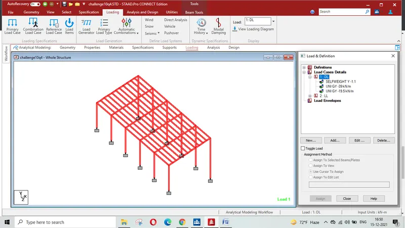
Model with given data has been prepared using Staad-Pro and loading is also assigned as per given data. Here it is to mention that loading on thf Gable fram is half of the main frame. Load have been multiplied with the bay width in order to arrive loading in KN/m for assigning it on members. Staad fille for refrence is attached.
Print screen of model with self load-
Print screen of model with Dead load-
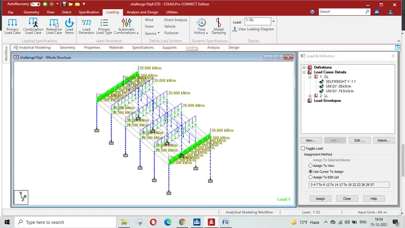
Print screen of model with Dead load-
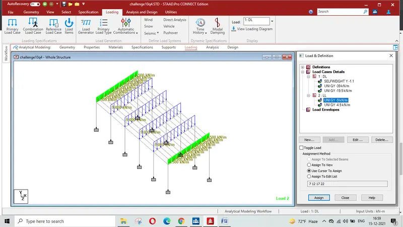
Print screen of model with wind load-
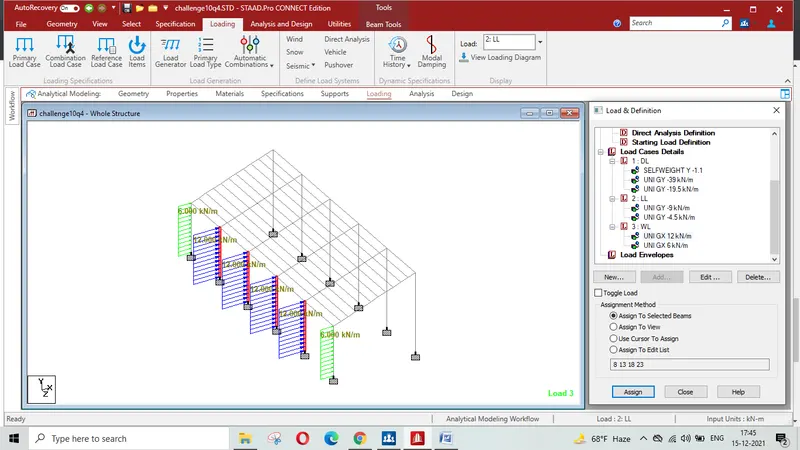
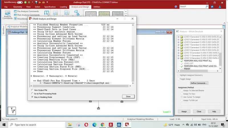
Run analysis command has been performed successfully with 0 Errprs, 0 Warning & 0 Note as sdhown below-
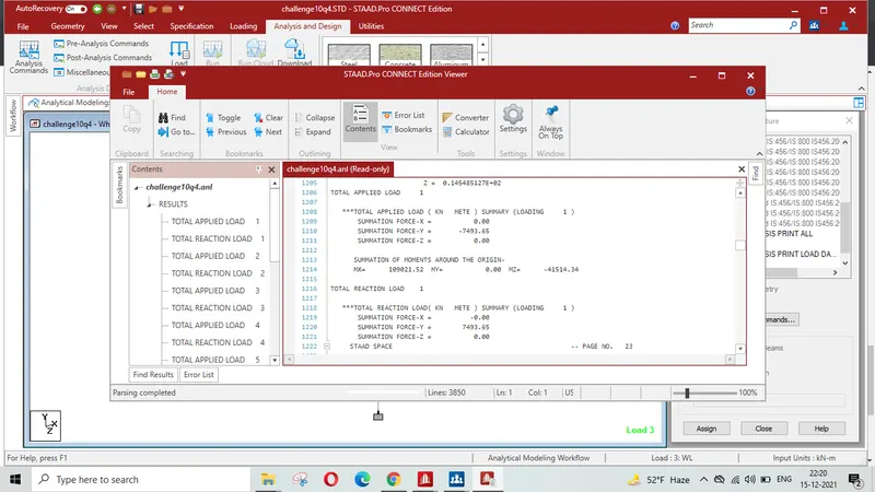
Static Load Analysis:
LOAD CASE-1 (DL)
SUMMATION FORCE-Y = -7493.65 KN
SUMMATION FORCE-Y = 7493.65 KN
LOAD CASE-2 (LL)
SUMMATION FORCE-Y = -478.87 KN
SUMMATION FORCE-Y = 478.87 KN
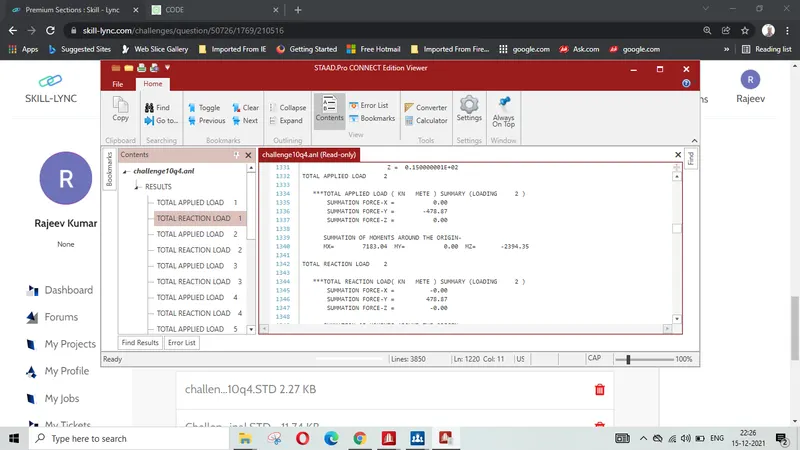
LOAD CASE-3 (WL)
SUMMATION FORCE-X = 360.00 KN
SUMMATION FORCE-X = -360.00 KN
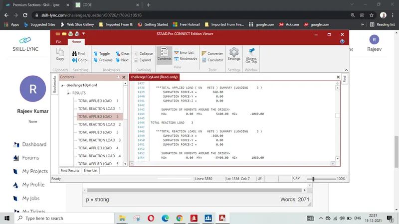
LOAD CASE-4 ( EQUIVALENT LOAD AS PER IS 456)
SUMMATION FORCE-Y = -11958.79 KN
SUMMATION FORCE-Y = 11958.79 KN
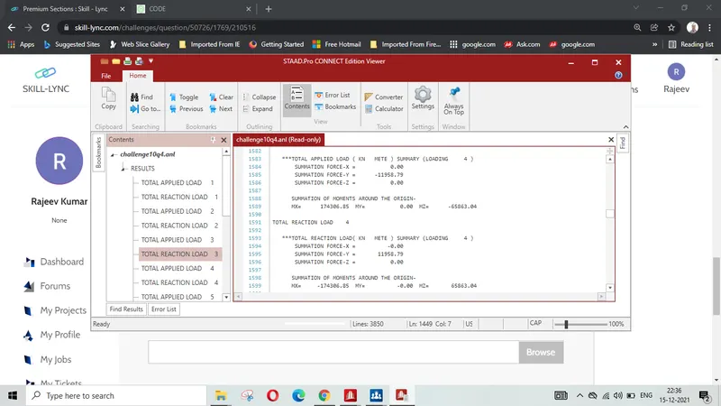
LOAD CASE-5 ( EQUIVALENT LOAD AS PER IS 456)
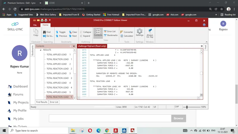
SUMMATION FORCE-X = 432.00 KN
SUMMATION FORCE-Y = -9567.03 KN
SUMMATION FORCE-X = -432.00 KN
SUMMATION FORCE-Y = 9567.03 KN
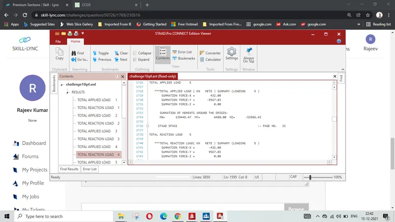
LOAD CASE-6 ( EQUIVALENT LOAD AS PER IS 456)
SUMMATION FORCE-X = -432.00 KN
SUMMATION FORCE-Y = -9567.03 KN
SUMMATION FORCE-X = 432.00 KN
SUMMATION FORCE-Y = 9567.03 KN
LOAD CASE-7 ( EQUIVALENT LOAD AS PER IS 456)
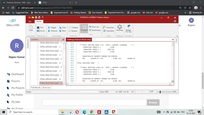
SUMMATION FORCE-Y = -9567.03 KN
SUMMATION FORCE-Y = 9567.03 KN
LOAD CASE-8( EQUIVALENT LOAD AS PER IS 456)
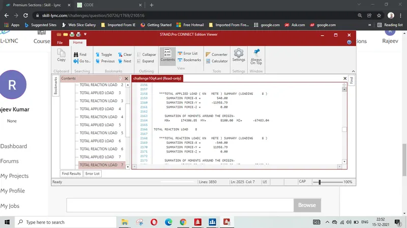
SUMMATION FORCE-X = 540.00 KN
SUMMATION FORCE-Y = -11958.79 KN
SUMMATION FORCE-X = -540.00 KN
SUMMATION FORCE-Y = 11958.79 KN
LOAD CASE-9 ( EQUIVALENT LOAD AS PER IS 456)
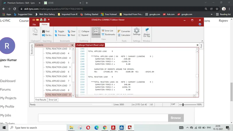
SUMMATION FORCE-X = -540.00 KN
SUMMATION FORCE-Y = -11958.79 KN
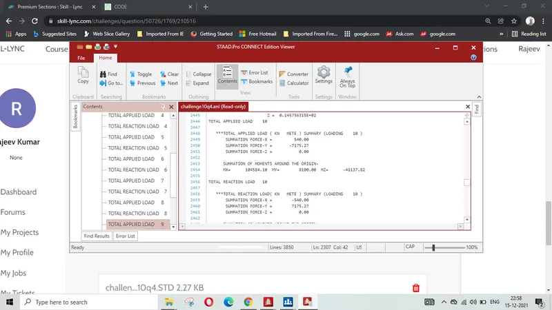
LOAD CASE-10 ( EQUIVALENT LOAD AS PER IS 456)
SUMMATION FORCE-X = 540.00 KN
SUMMATION FORCE-Y = -7175.27 KN
SUMMATION FORCE-X = -540.00 KN
SUMMATION FORCE-Y = 7175.27 KN
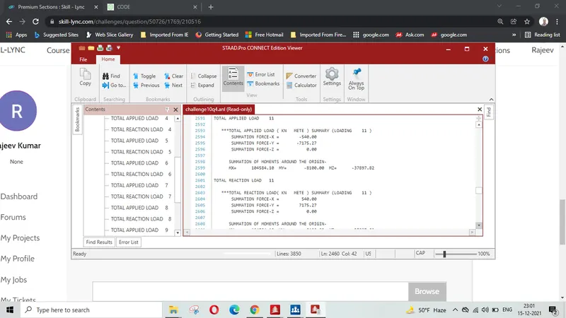
LOAD CASE-11 ( EQUIVALENT LOAD AS PER IS 456)
SUMMATION FORCE-X = -540.00 KN
SUMMATION FORCE-Y = -7175.27 KN
SUMMATION FORCE-X = 540.00 KN
SUMMATION FORCE-Y = 7175.27 KN
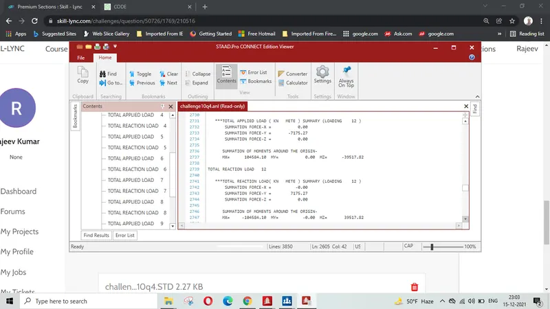
LOAD CASE-11 ( EQUIVALENT LOAD AS PER IS 456)
SUMMATION FORCE-Y = -7175.27 KN
SUMMATION FORCE-Y = 7175.27 KN
Challenge STD 3.14 KB final file with load combination is attached.
RESULT : Thus it is concluded that:
1) Model is prepared as per given data and loadings are assigned
2) Vertical download forces for various loadin are equal to Upward forces , and Forces on left side are equal to forces on Right side .Thus static equlibrium is maintained.