Week 10 - Challenge 3 - Door Trim Lower with Engineering Features
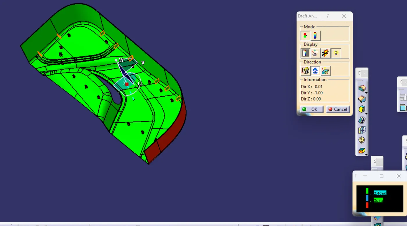
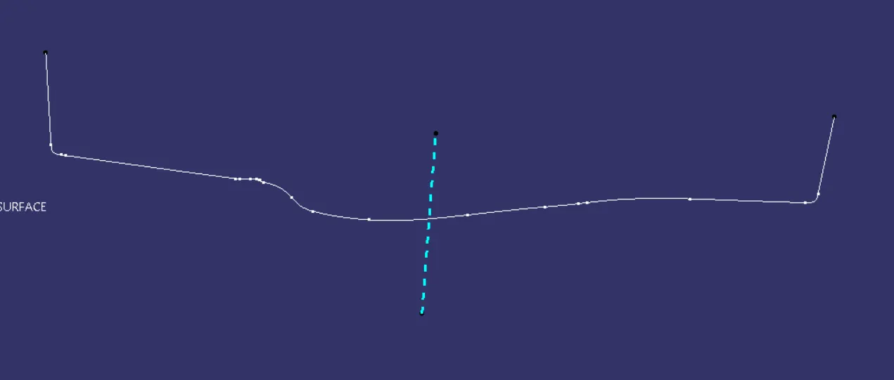
Initially tooling axis is created using intersection and draft analysis was done for the provided A surface
Offseted the A surface to 2.5 mm to create the B surface
The Proper changes were done on the offseted surface to complete the b surface
Class C surface was done from A suface keeping tooling in mind as the draft was give towards the A surface as the a surface will not came in contact with any of the mold flow from the tool
Then A and C surfaces was together trimmed
Intersection was taken with Class b and A-C trim and proper changes was done to B surface
Trimmed the A-C surface with B surface and final surface is formned
Then in the part design Closed part is given to form the final Output that is 2.5 mm thick plastic part
A plane is created along a point to create 4 way locator
Sketches are created for the 4 way locators
Sketch is padded along with the tooling axis with a thickness of 1mm
Draft is provided which is .5 deg
Edge fillets of 0.3 mm is given
A copy is generated since 2 locators are required.
Sketches are created for the heatstakes with an thickness of 1 mm per side
Paded along with the tooling direction
Another sketch is created for the rib of the heat stake
Paded with 1mm thickness
draft is provided
Fillets or .3 mm is given
The rib is trimmed with the heatstakes removing unwanted section.
Copy of the trimmed sections were generated and transfered to the required points using point to point transition
The parts are union trimed with the main body removing unwanted face
Final Draft Analysis were done.
Tooling Axis
A Surface Draft Analysis
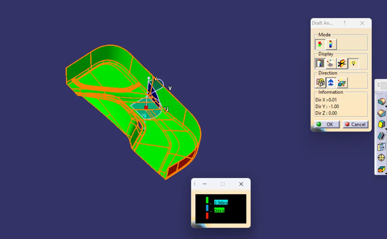
Final surface Draft Analysis
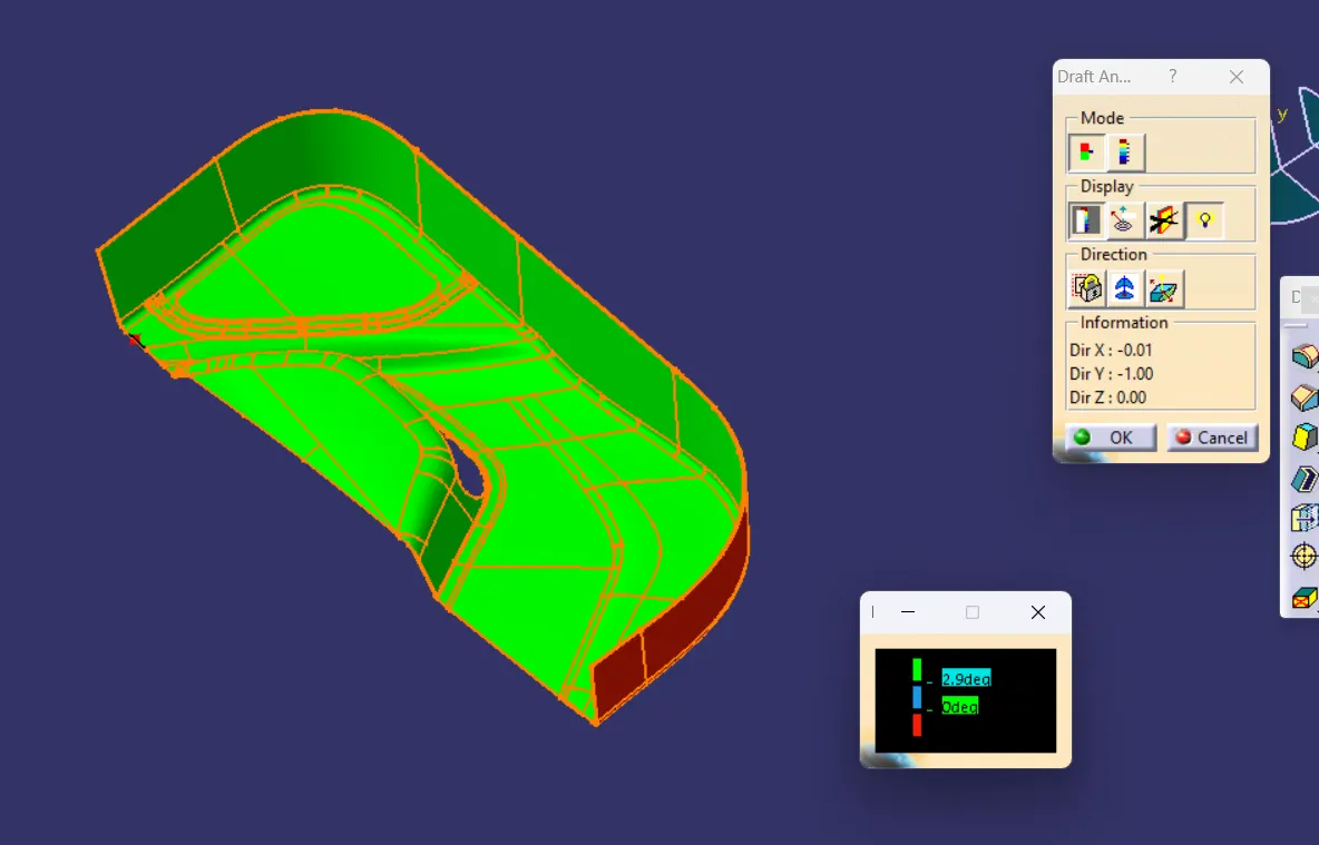
Final Draft Analysis