Week 10 - Challenge 3 - Door Trim Lower with Engineering Features
AIM:
- Create the Door Trim Lower Plastic component through the given Class-A surface. To begin with, the tooling axis for the given Class-A Surface should be created meeting the requirements of the draft angle and at the end perform the Draft analysis on the model.
- Create the Heat Stakes and the locators considering the design rules mentioned in the video for the door applique.
Draft:
- The draft is the amount of taper for moulded or cast parts perpendicular to the parting. line. Draft angles are a design consideration that makes it much easier for a part to release cleanly from a mould. A draft angle is calculated as a degree measurement (or, less often, an inch or millimetre measurement) from the vertical axis of a mould, and it helps account for thermoplastic shrinkage, a practical reality of the injection moulding process for most materials.
- Draft angles are generally a requirement of injection moulding design (though there are a select few soft materials, like nylon, that can get away with draft angles of zero). The draft should be a part of the design for manufacture, and all stakeholders and contributors should be aware of its need at the outset of the design process. This includes product designers, design engineers etc and this allows considerations for design requirements to be taken into account. Any draft is always better than no draft.
Importance of Draft:
By accounting for thermoplastic shrinkage during the cooling process, draft angles significantly reduce friction between the finished, cooled part and the side of the mould, Not only does this create a much easier release process, but it also offers several other benefits, depending on the design of the part which is as follows:
• Reduces the chance of damage to the part due to friction during the release.
• Reduces wear and tear and chances of damage to the mould.
• Ensures a uniform, smooth, unscratched finish when required. • Ensures the integrity and uniformity of other surface finishes and textures.
• Reduces overall cooling time by lessening or eliminating the need for unconventional ejection setups.
• Most, if not all, of these benefits, offer either direct or indirect overall production cost reductions.
Overview:
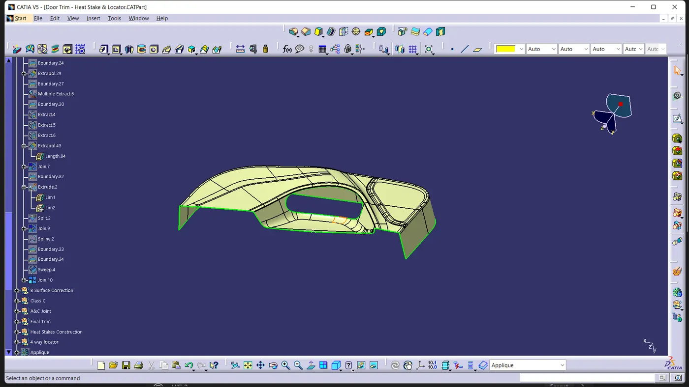
Initially, we need to offset the given Door Trim class A surface in the inner direction to the required thickness (here the thickness is 2.5mm). After that, we need to close the patches on the offset surface of the bumper, the patches are formed due to the fillets on the Class A surface. Once all the patches are closed properly join them together to make a proper class B surface and now sweep the boundary of the class A surface to trim with the class B surface to make a closed body. By using the closed body command in the Prat workbench we can get the solid body from the closed surface of the Door Trim. Now, I created the Heat stakes and Locators by considering all the design parameters. After creating all the B-side features on the solid part body of the door trim, I performed a draft analysis for it to check whether all the surfaces are drafted properly or not (The draft angle for the plastic component is 0.5deg to 3deg).
TOOLING AXIS:
To create the tooling axis, I extracted a surface from class A and created a point in the middle of the surface by using the point command and created a line at that point through the x-axis. Now, I performed a draft analysis check from that line whether the created tooling axis is in the correct position or not. If in the draft, analysis check the surface highlighted with green colour on both sides of the surface the tooling axis is in the correct position and direction.
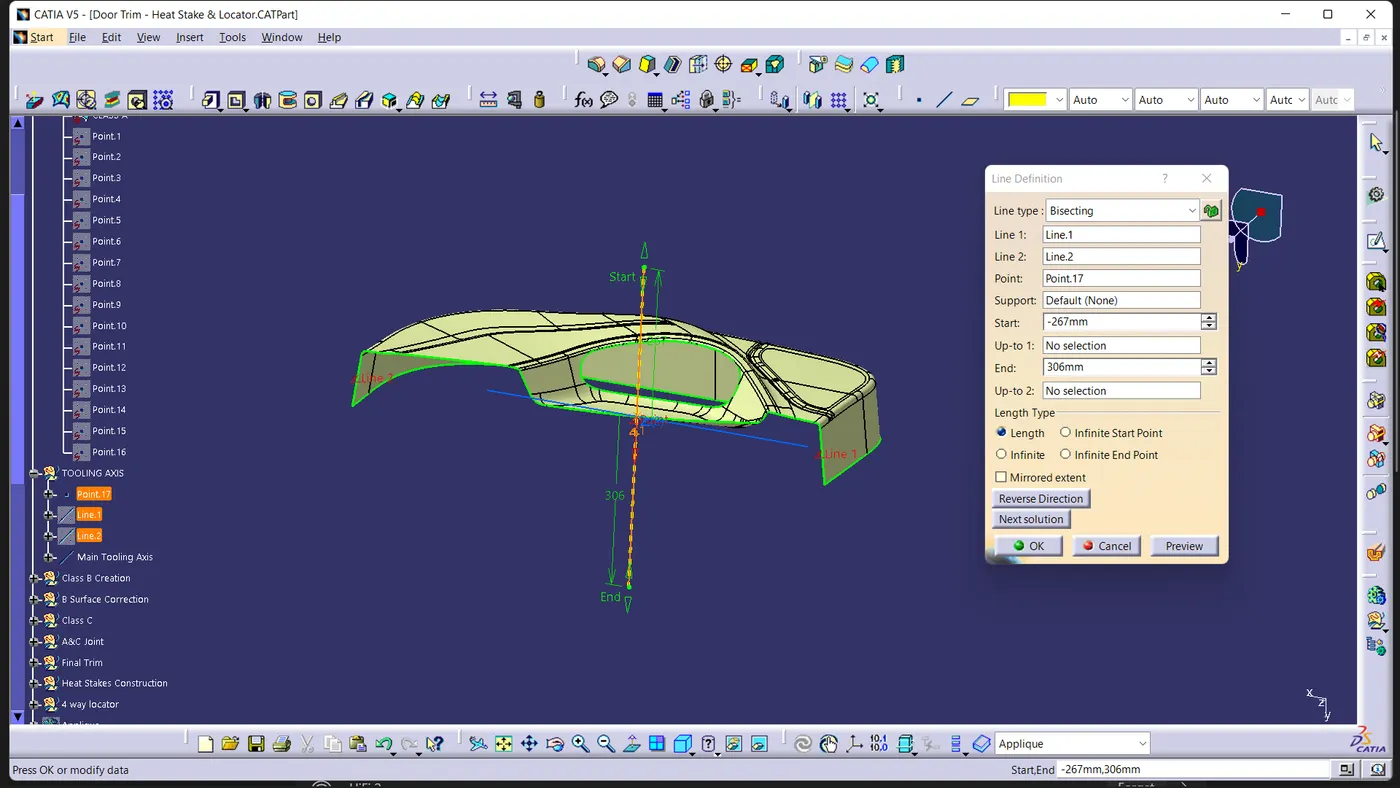
Tooling Axis By Bisecting Method
- Check the connectivity of given Class A Surface i.e no gaps between the surfaces.
- Analyse the component along x,y,z direction and check which is the best possible tooling direction (Here Y)
- Create a point at base surface by extracting it.
- Create an axis system with that point as origin.
- Create an intersection of class A in xy axis
- Create two lines with reference of faces which we think will create problems.
- Create a bisecting line with the lines drawn, which will gives us the tooling axis.
Heat Stake:
In manufacturing products with thermoplastic components, it is often necessary to join a thermoplastic to apart of dissimilar material, whether it be a metal, dissimilar plastic or other material. This technical information sheet provides design guidelines, configurations and techniques for successful heat staking.
Thermal Staking or Heat staking is an assembly method that uses the controlled melting and reforming of plastic stud or boss to capture or lock another plastic or metal component of an assembly in place. The plastic stud protrudes through a hole in the component to be locked in place. The heated thermal tip contacts the top of stud, which melts and fills the volume of the tip cavity to produce a head, locking the component in place. The progressive melting of plastic under continuous pressure forms the head. When staking, the right combination of heat and pressure for the application is critical.
Heat staking also known as thermoplastic staking is the process of joining two dissimilar materials together. In heat staking we use local heating and cooling to raise the temperature of plastic components and allow plastic reforming to be carried out. This reforming can be used in a wide variety of applications.
Applications range from staking plastic boss’s for assembly of car door panels to joining PCB’s to plastic housings.
DRAFT ANALYSIS:
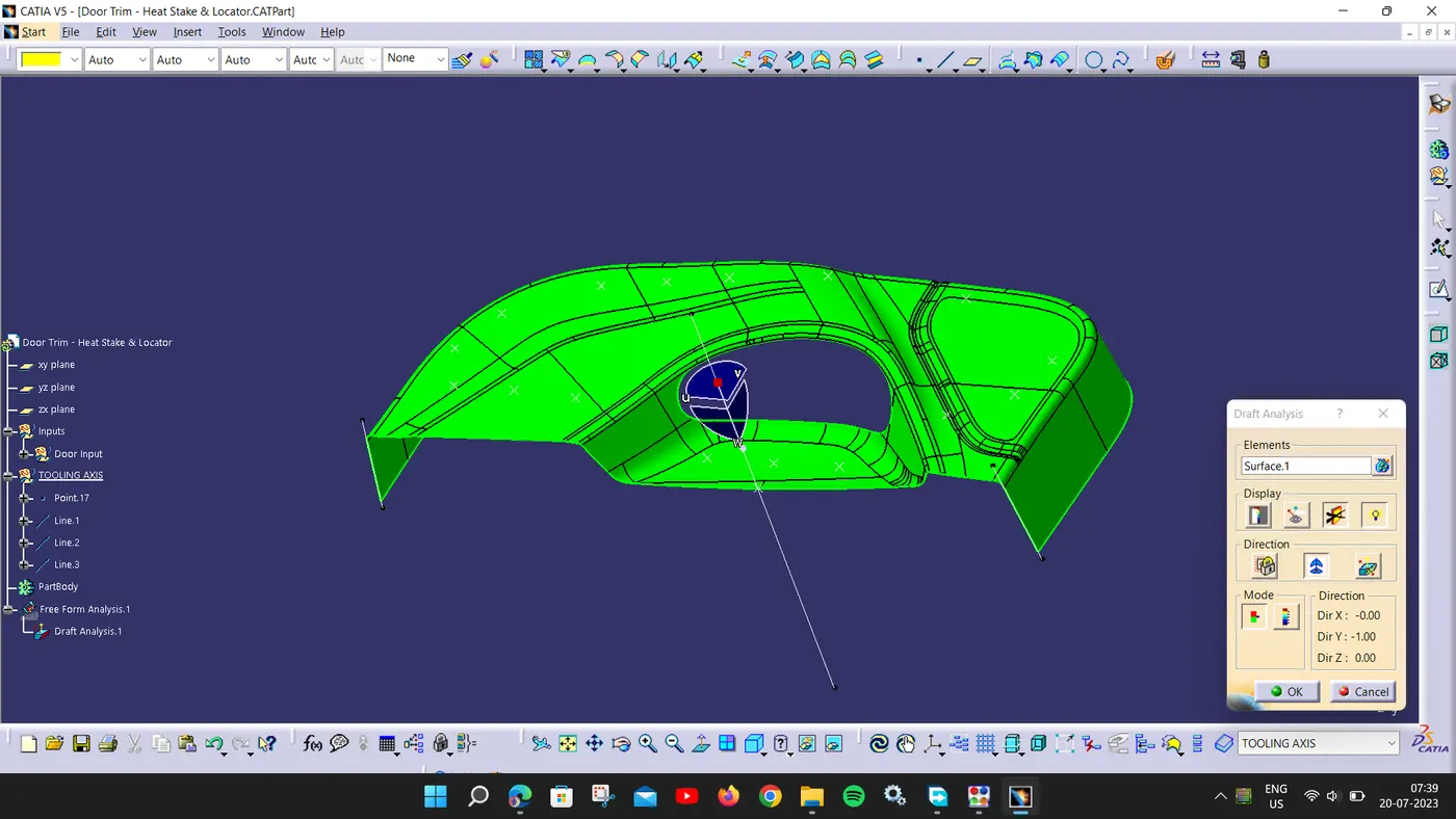
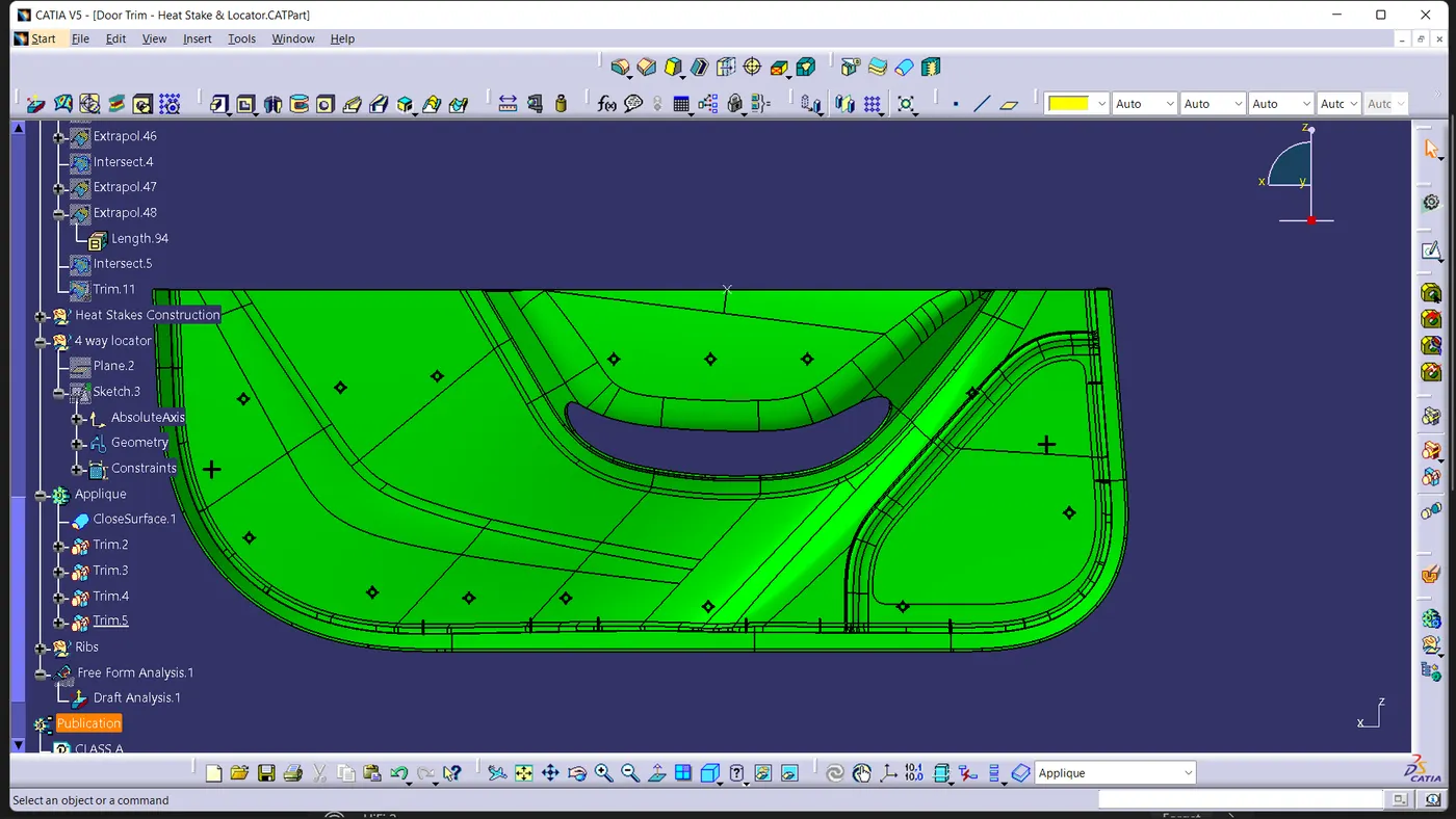
Now perform the Draft analysis using the Featured Draft Analysis tool in the tools.Once the draft analysis toolbar is opened, go to the display block and select the 'Analysis under the running point' command to check the angle for different sides on the class A surface. The color scale on the bottom visualizes, whether the draft angle meets the requirements or not (3 deg) by indicating the colors Green, Blue and Red. Once the draft angle analysis was done, we need to align and fix the compass to the tooling axis of the class A surface.
Class B Surface:
Class C surface:
Now creating Class C Surface:
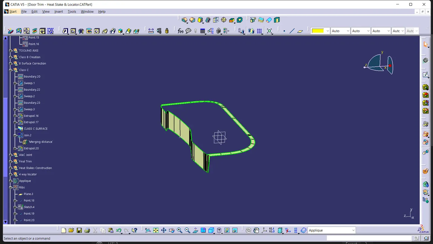
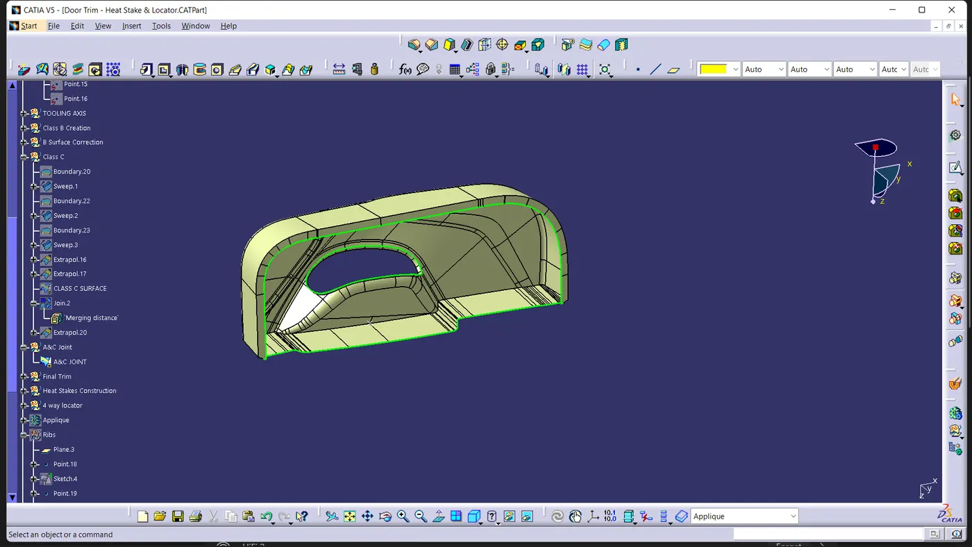
- C surface has been created from the boundary lines of class A surface and by extracting the supporting surfaces then sweep the boundary lines with reference to the extracted surfaces.Create a sweep with reference to the draft direction and the reference surface with a 90 degree angle(for surface edges perpendicular to tooling axis)
- Create a sweep with reference to the draft direction with a 3 degree angle(for surface edges parallel to tooling axis)
- Give the inside direction Check for the continuity of the surfaces if there is any gap go for extrapolated and trim all together now we will get the class C surface
Joining A&C surface:
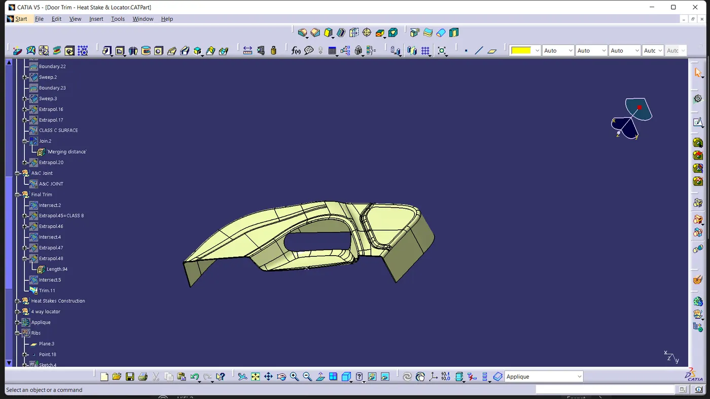
Final Closed Surface:
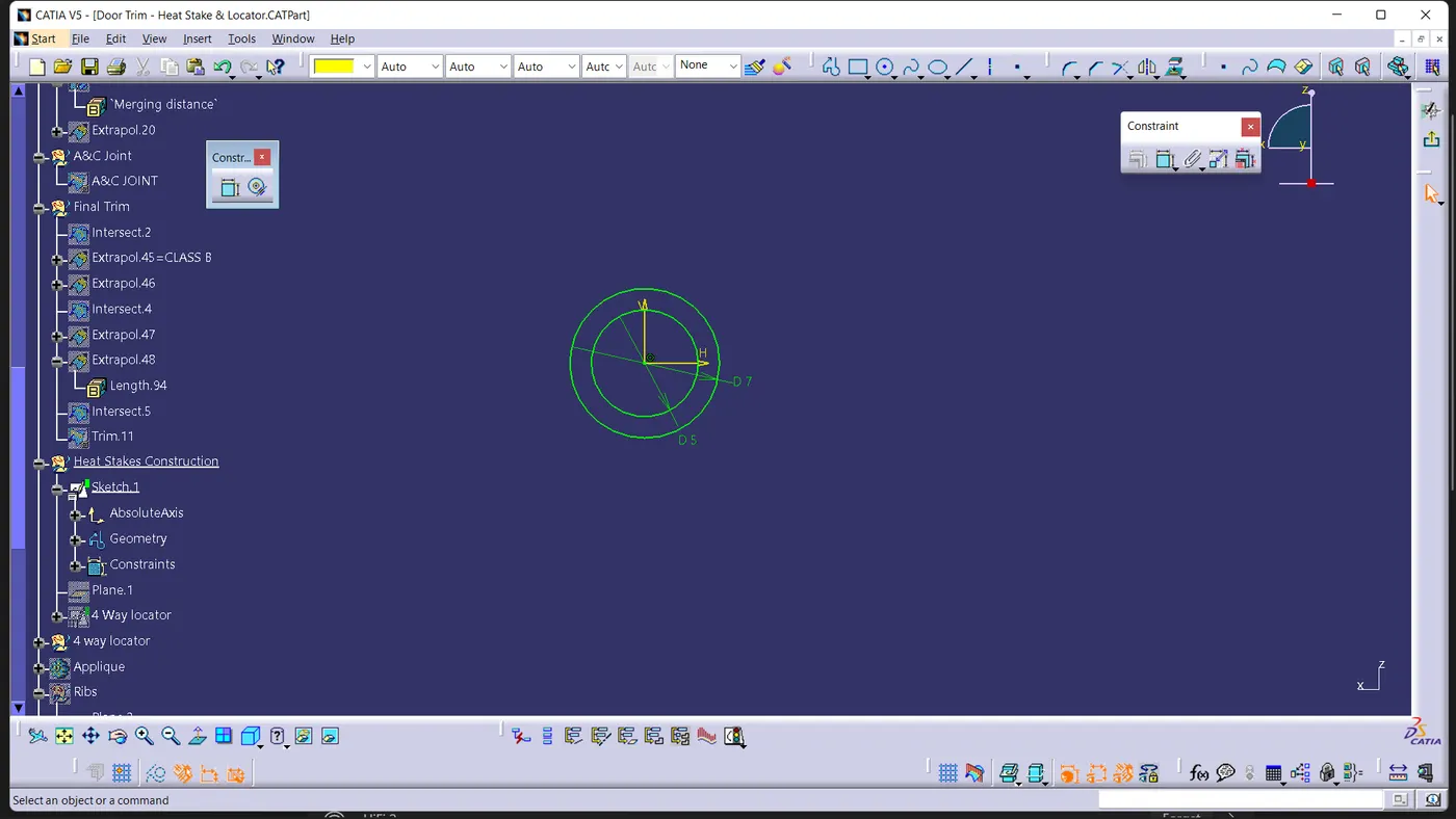
Heat stakes:
The heat stakes are 5mm less than the four way locator.
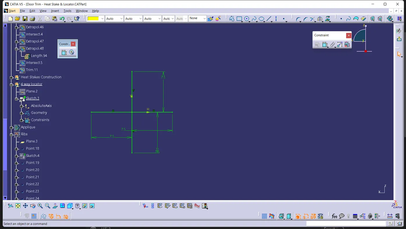
Four way locators
The four way locators are designed on respected places where the location assingned for the four way locator.
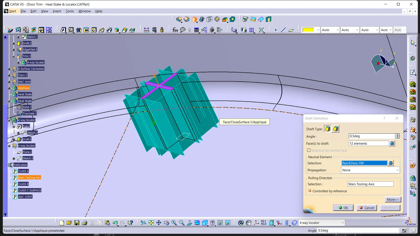
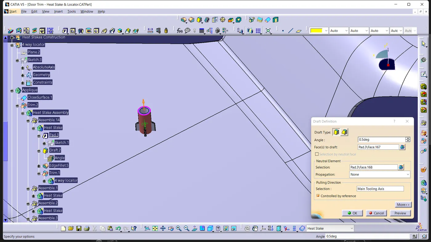
The paded surface was drafted a surtain angle of 0.5 deg and the edges are filleted to 0.25mm.
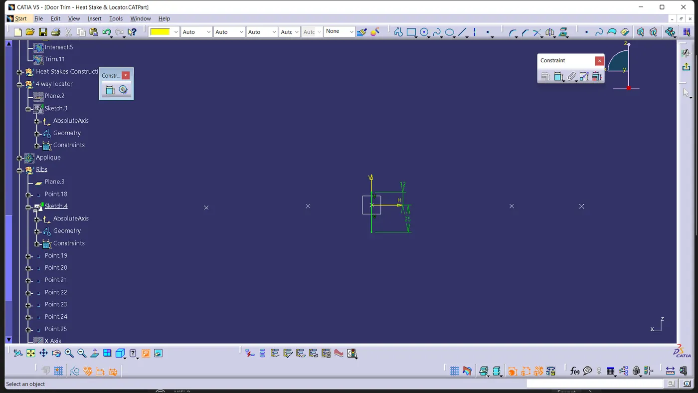
The paded surface was drafted a surtain angle of 0.5 deg and the edges are filleted to 0.25mm.
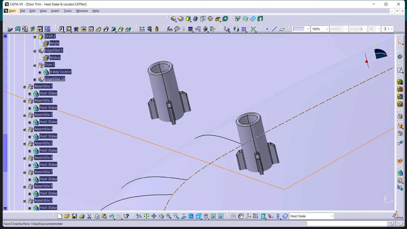
4 Way Locator Draft:
Final Solid Body Part:
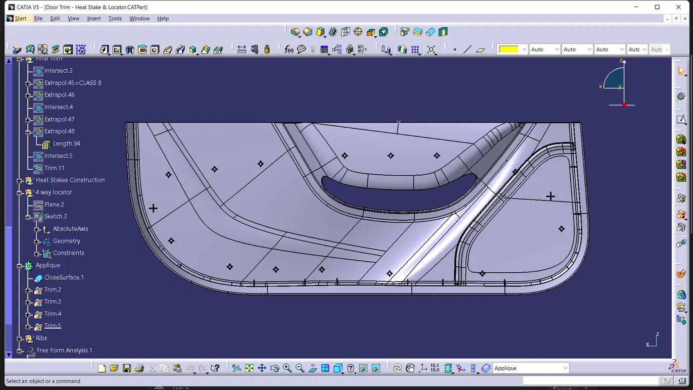
Solid part Draft Analysis:
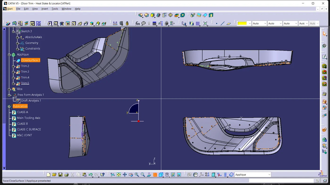
Diffrent View of Door Applique:
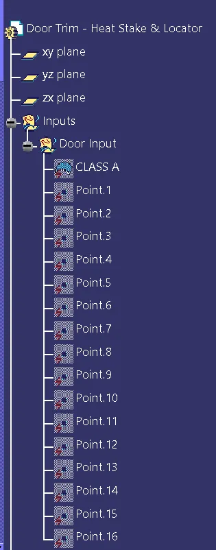
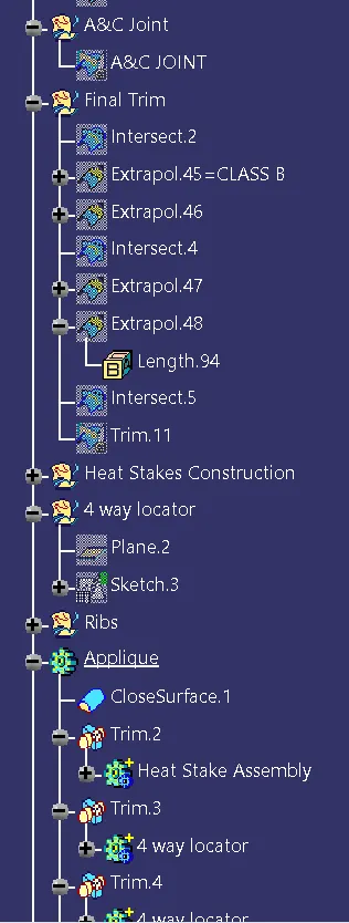
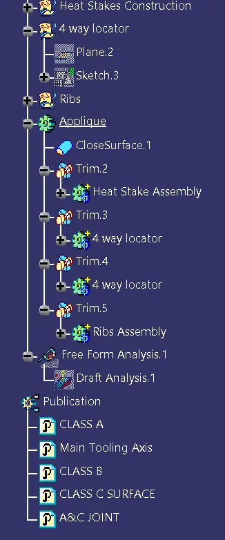
Tree Structure:
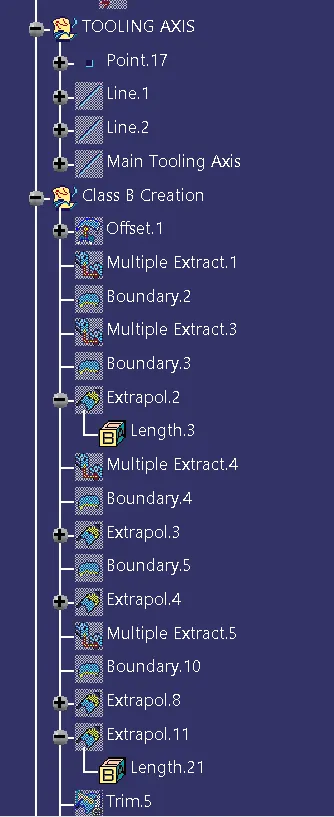
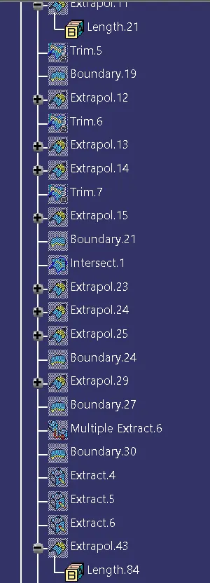
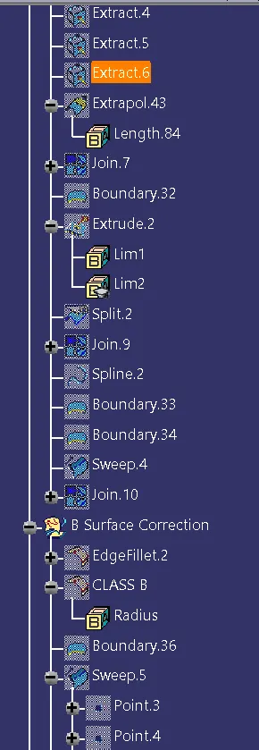
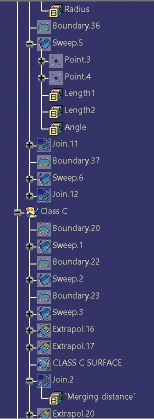
Conclusion:
- Door Trim lower plastic component with Heat Stakes and the locators considering the design rules has been created in Catia.