Week 10 - Challenge 3 - Door Trim Lower with Engineering Features
Design of door trim with lower Engineering feature
AIM:
- To create the door trim (closed volume) component alog with it's lower engineering features (Heat stakes & locators)
- To perform the draft analysis of the final component also on the heat stakes and locators as per design consideration.
Procedure followed:
The following steps are included while designing the door handle with B side features
- Tooling axis creation
- Draft analysis of class A surface
- Class B surface generation
- class C surface generation
- Final trim
- Solid body generation
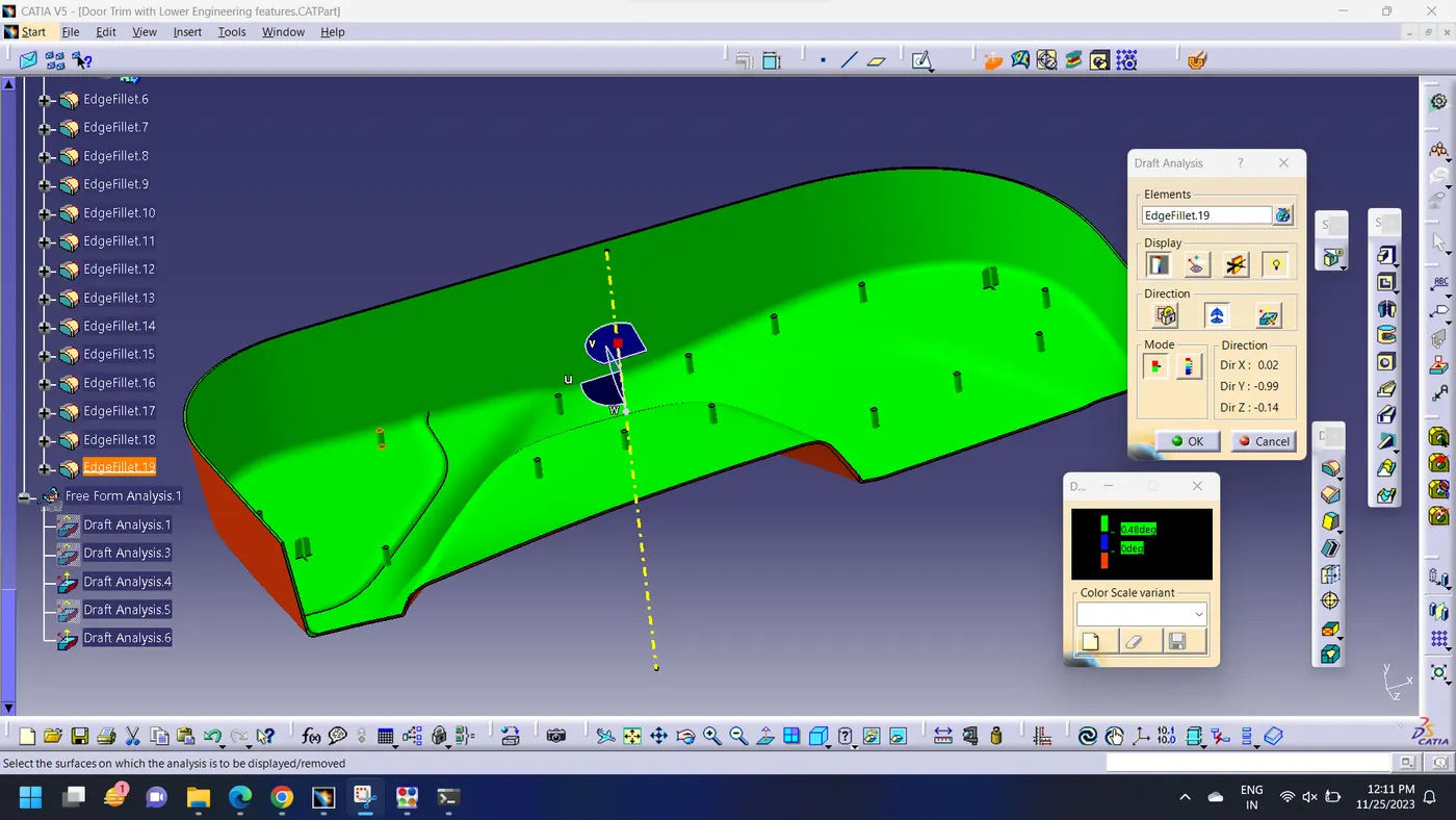
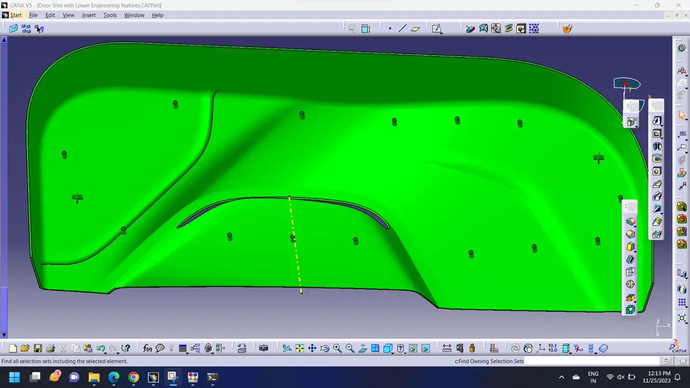
- Draft analysis of the solid body
- Locator creation
- Heat stake creation
- Translation
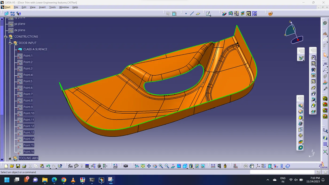
The given Class A surface is checked for gaps or irregularities using boundary or join command. Here no such issues were present.
Tooling Axis creation
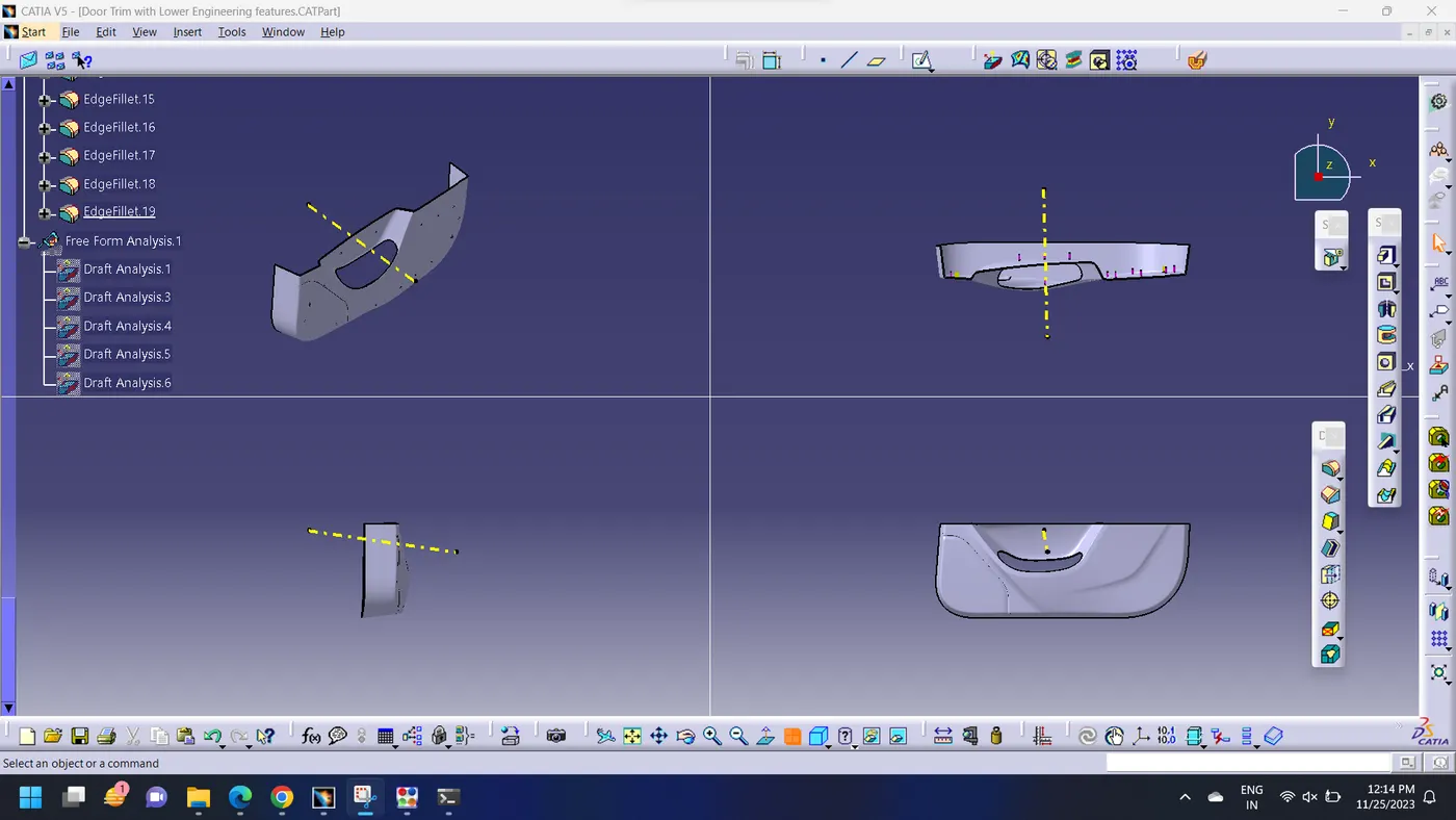
Orient the class a surface in various views and opt the best view to manufacture the part in a single go. Then extract the surface out from the class A surface and create a point at the mid point of the extracted surface and create a line in the view direction and mark it as the tooling axis.
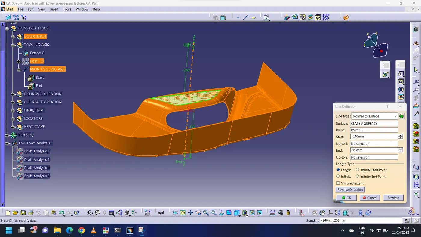
Draft analysis on class A surface:
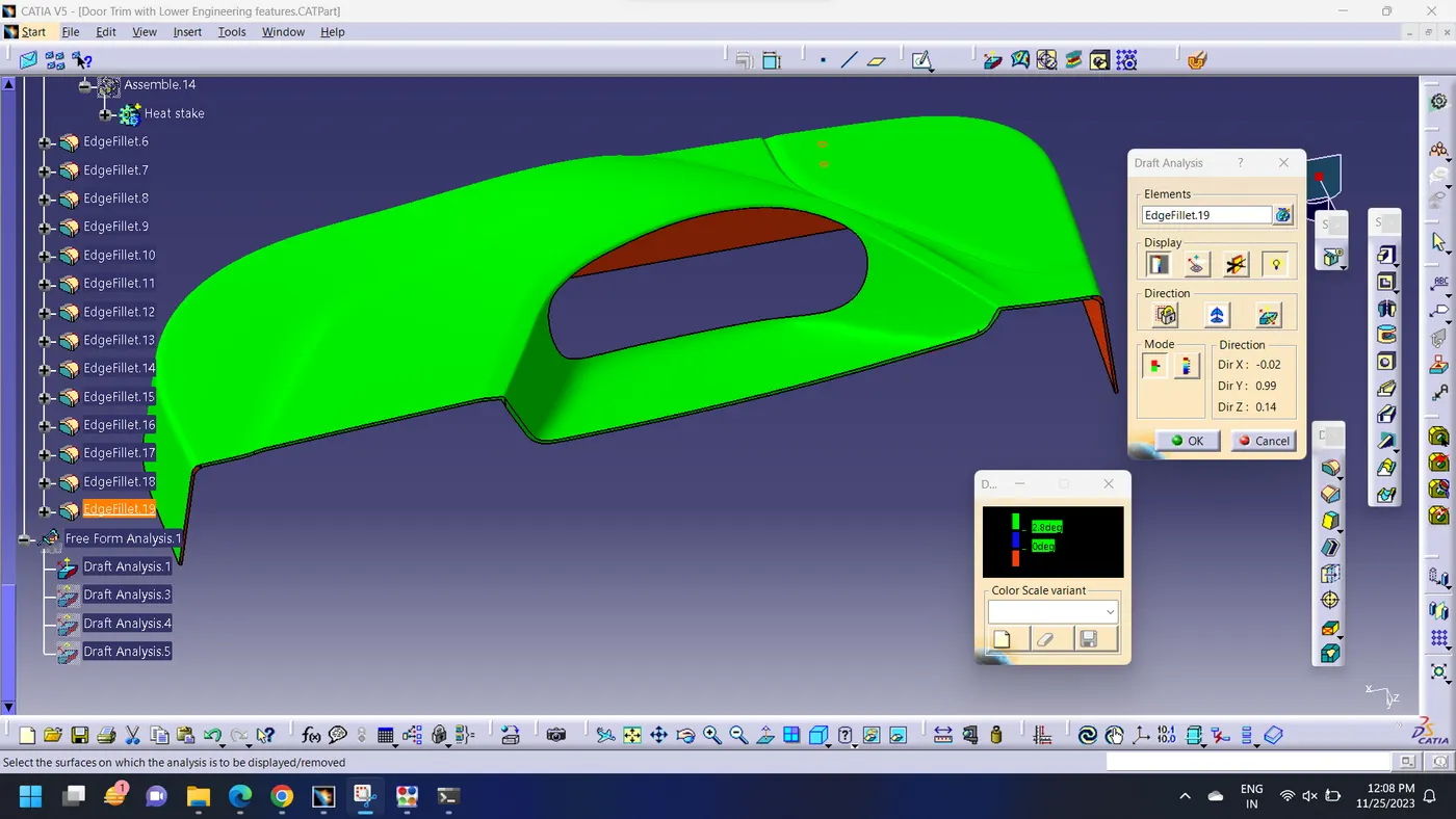
Now perform the draft analysis of the Class A surface with respect to the tooling axis created so that the surface of the Class A need to clear the draft of 3deg
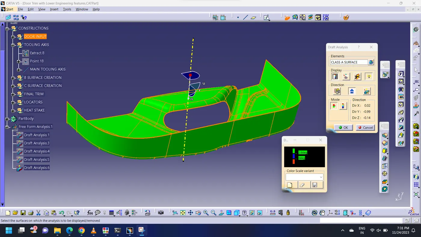
Hence it can be seen that the above given class A surface is clearing at 3 deg draft so we can further for creation of B surface.
Class B surface Creation
- To create the B surface we need to offset the class A first due to its complex curvature profile.
- class A has been offseted to 2.5 mm as per given thickness of the component.
- After offseting the class A the B surface will have some patches to be resolve later. The patches is shown below
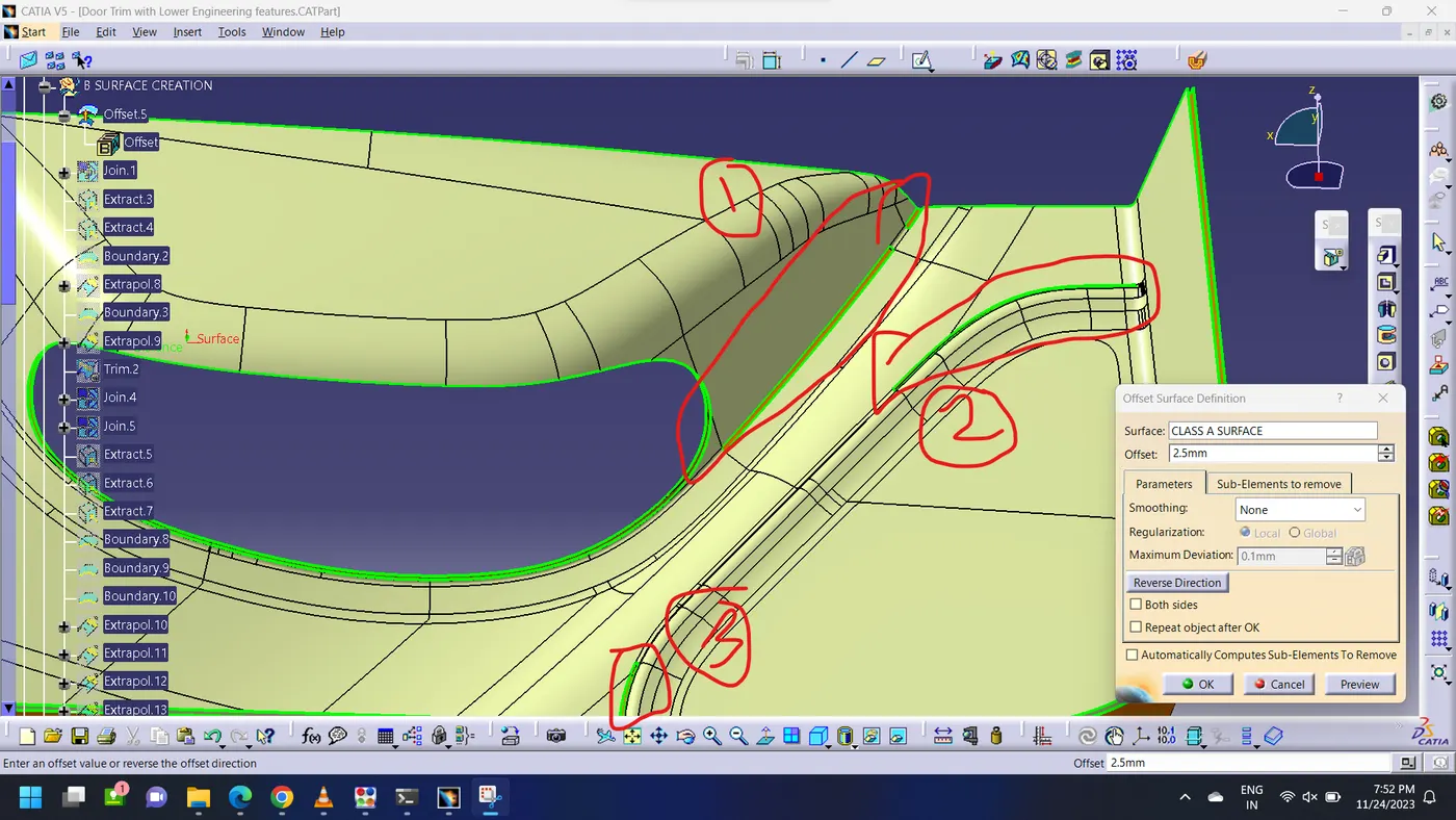
To fix the above patches we need to split the surface into pieces wherever there is open profiles it is shown in the images below.
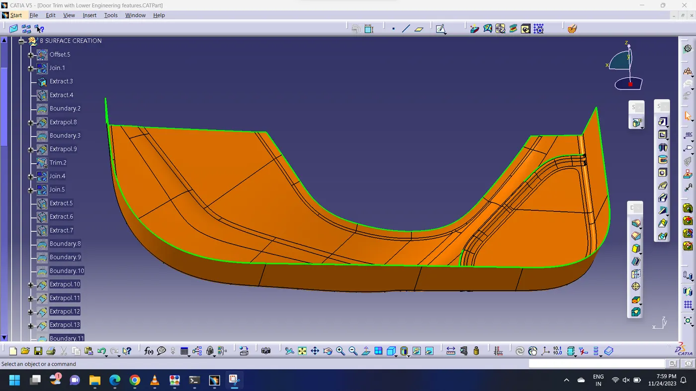
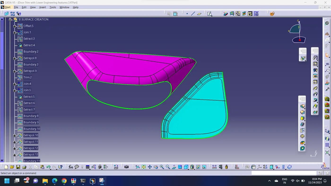
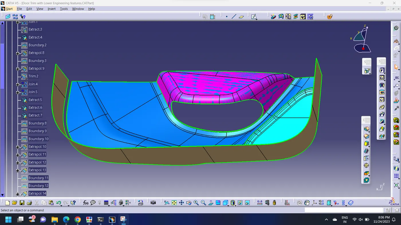
- So then after extraction of these surfaces we have to extrapolate all the surfaces till it intersects with each surfaces.
- Finally trim them to get a proper Class B surface.
Creation of Class C surface
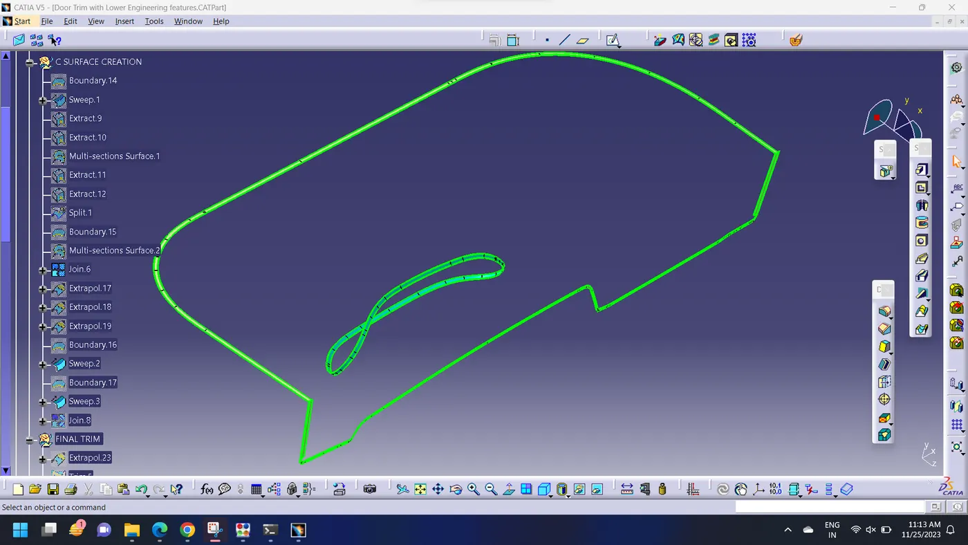
Sweep command is used to create Class C surface from the boundary of Class A surface. The draft angle with respect to the tooling axis is taken as 3° for faces perpendicular to the tooling axis. For faces that are parallel to the tooling axis, sweep angle is taken as 90° with respect to the surface.
The boundary of Class A is not taken in a single stretch since the generation of C surface does not occur correctly. It is taken as multiple boundaries, providing different limits and sweep operation is done separately for those regions. At some regions where we need to connect these individual sweep surfaces, we use spline, boundary and multi section surface commands.
Final Trim
Now trim the class B surfcae with the combined class A and class B surface to obtain the final plastic component
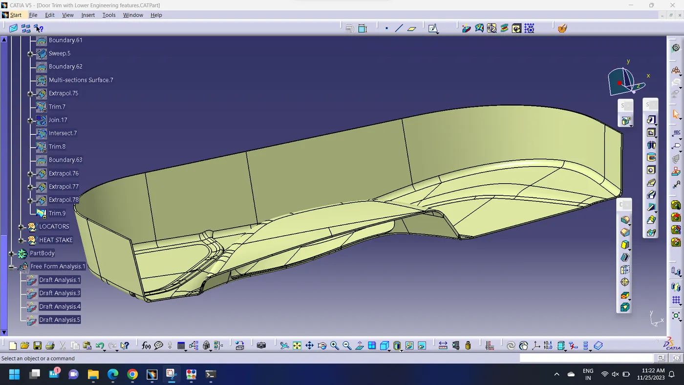
Make it into solid body (Closed volume)
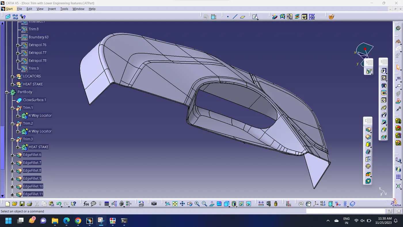
Creation of Locators
Locators are used to positioned the component in exact location and act as a guide for joining the two component.
- There are mainly two type of locator four way and two way locator
- Locators can be designed by following the same guidelines for that of ribs.
- First create the points where we want the locators.
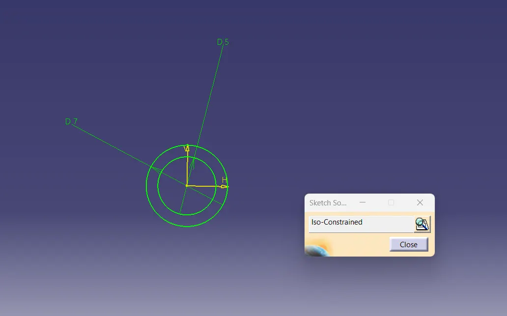
- Extract the base surface of class A from the solid body and create a reference plane with reference to the point then draw the base lines by iso constrained positioned sketch method and chamfer it.
- Extrude the reference line by giving the proper height and thicken it to the required size then give proper draft by considering pulling direction as tooling axis.
- Apply proper fillet to the edges and verify all the dimensions on the rib then add it to the main body.
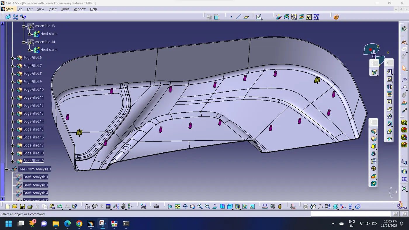
- Multiple copies of the locator can be created by using copy and paste with special options then translate it by using suitable method.
- By removing the counter clearance body with main body will arrest the degree of freedom of the locators.
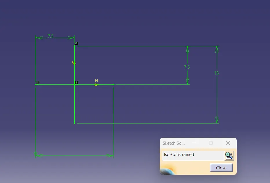
Guidelines for creating locator
- Min draft: 0.5mm per side
- Max fillet radius: 0.25mm
- Rib height: less than 5* nominal wall thickness
- Rib should be spaced with a height to width ratio: 3:1 or 2:1
Designing locators:
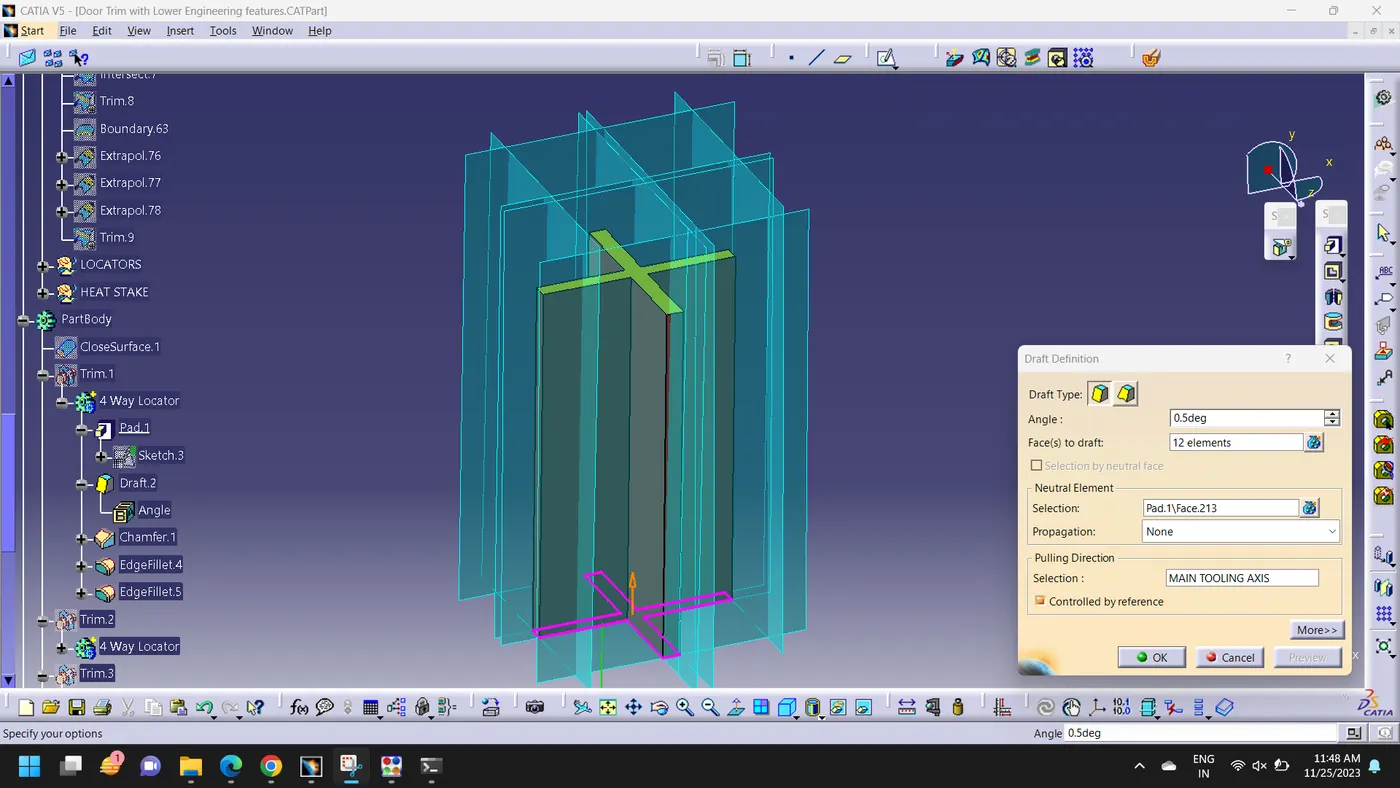
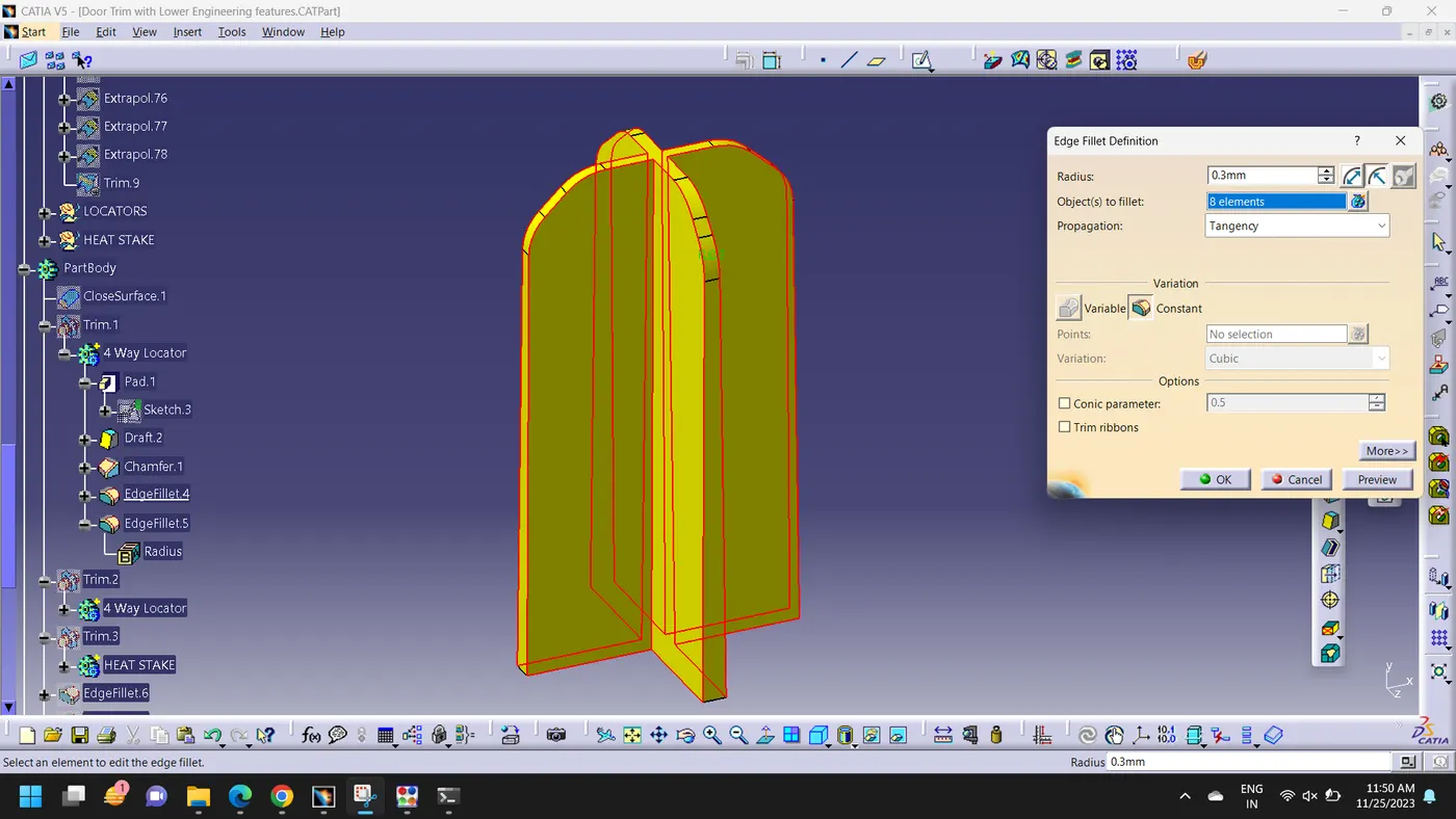
- Sketch for the locator is done.
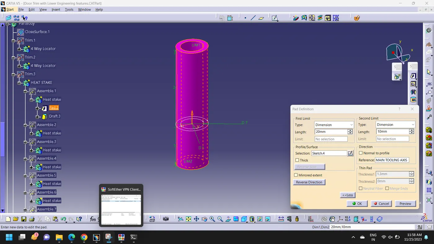
- Padding is done for a height of 22mm.
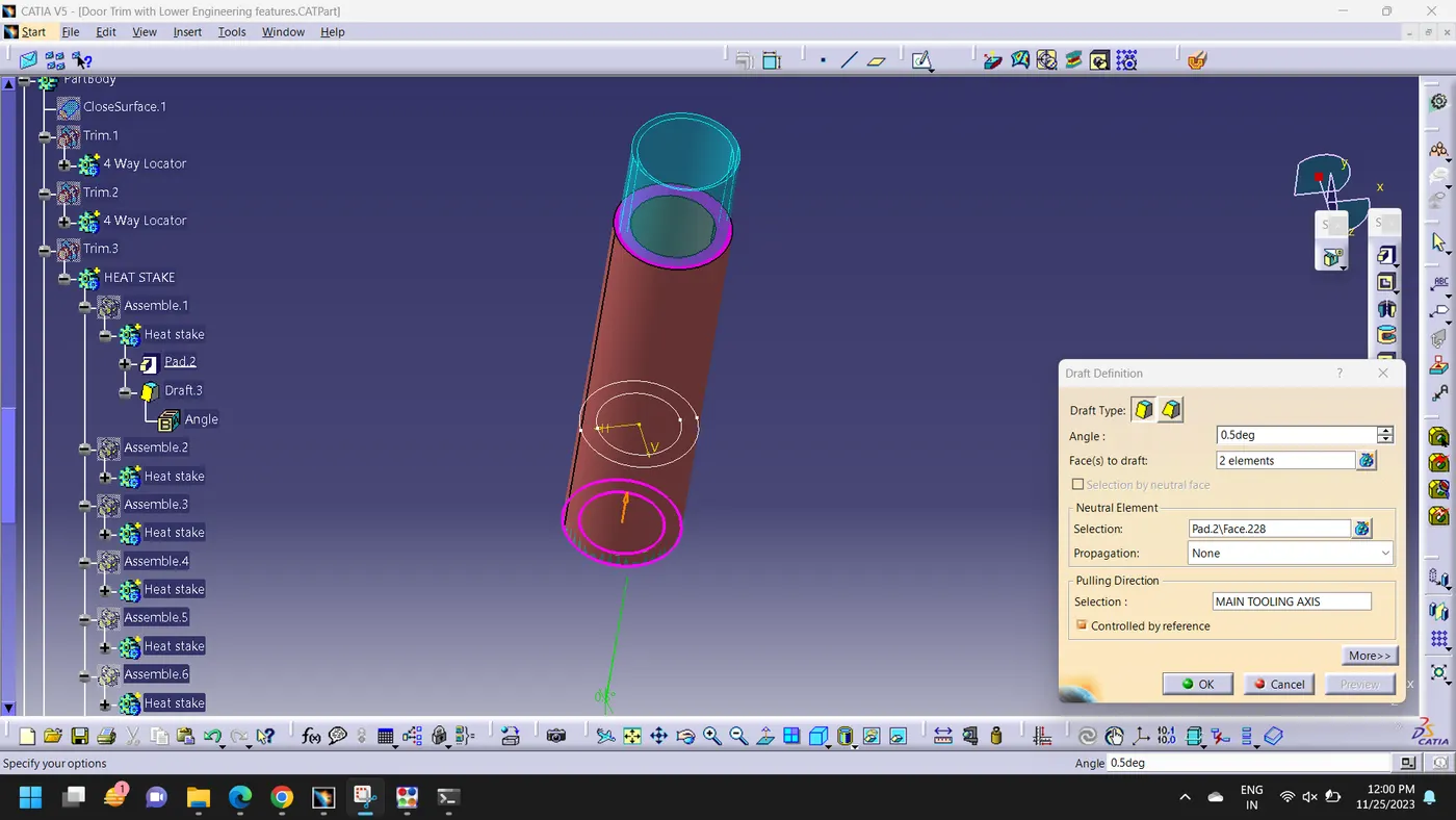
- Draft of 0.5° is given with the tooling axis as the pulling direction.
- Fillet of 0.25mm is given for the edges.
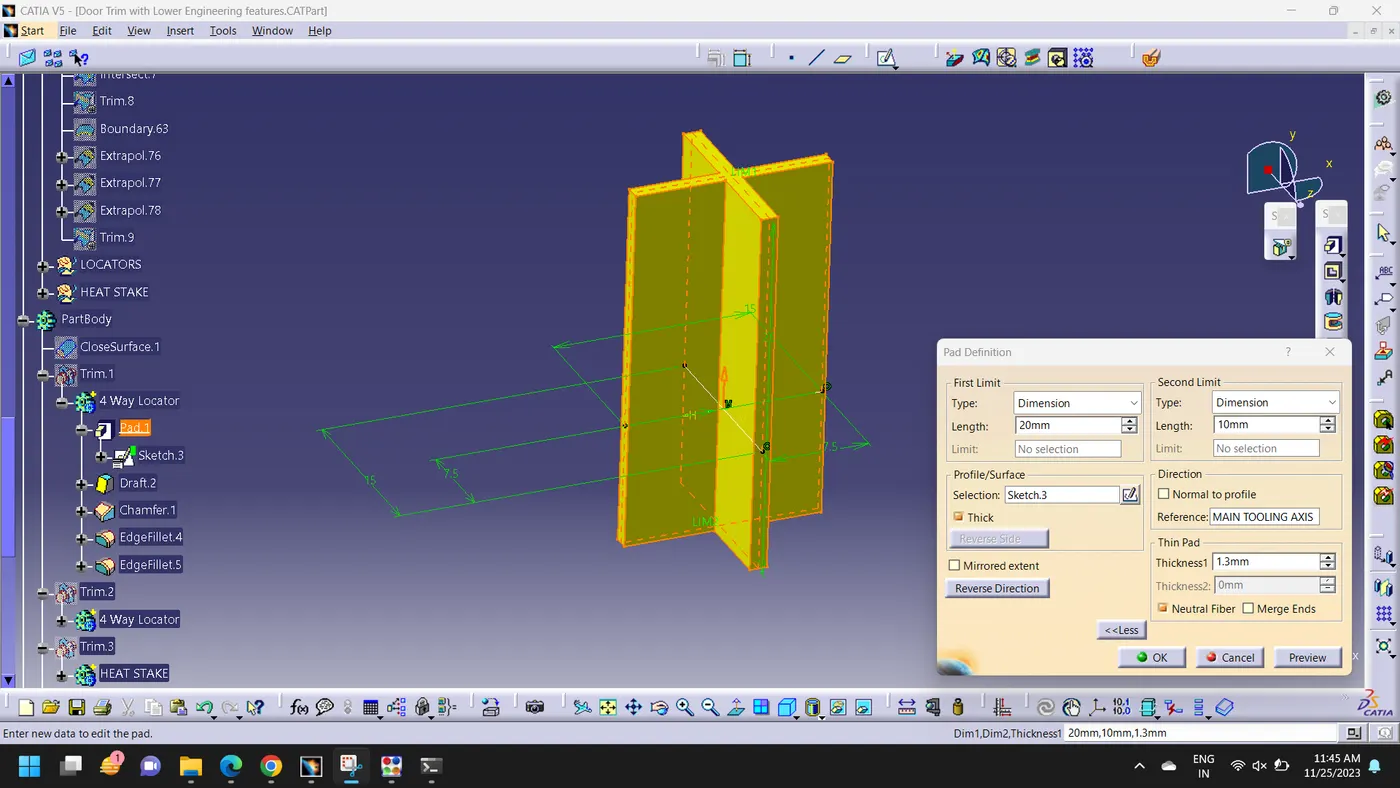
HEAT STAKES
- Thermal staking is an assembly method that uses the controlled melting and reforming of a plastic stud or boss to capture or lock another plastic or metal component of an assembly in place.
- Heat stakes is used to arrest the degree of freedom of locators by 3-2-1 principle in automotive tooling design.
The 3-2-1 principle is adopted for the part to part fixation in automotive industry. According to the 3-2-1 principle, a workpiece has 12 degrees of freedom.
- Translational movement along X axis.
- Translational movement along Y axis.
- Translational movement along Z axis.
- Rotational movement along X axis.
- Rotational movement along Y axis.
- Rotational movement along Z axis.
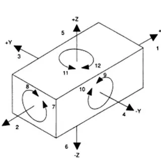
Fig 10. Twelve degrees of freedom.
To fix two components together, at least 11 degrees of freedom must be arrested. The remaining one degree is the fixing direction. In order to achieve this arresting, we create 4 way locators. The height of the locators should be greater than that of heat stakes.
Guidelines for creating heat stakes
- Min 15mm gap between heat stakes
- Max fillet radius: 0.25mm
- Max clearance with the counter clearance should be 0.5mm.