Week 10 - Challenge 3 - Door Trim Lower with Engineering Features
week 10 challenge:
DOOR TRIM LOWER WITH ENGINEERING FEATURE.
AIM:
To create a door trim lower plastic component through a given class a surface and also create a locator and heatstake on it.
software used:
catia v5 R20
procedure:
download the given class A surface, then open it on the catia v5.
CLASS A SURFACE:
using a boundary command in surface workbench, check whether it is joined properly or not.if not try to fix it.
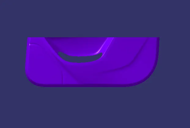
here is shows the class A surface.
TOOLING AXIS:
creation of tooling axis . check for the plane which should be easy to create using injecton moulding and choose a hole slot or a plane surface .
then create a point in it and a dummy tooling axis. then, check for a parallel and slope surface. using a intersect command draw a intersecting line of x and y separately.
then draw a tooling axis for x and y separetely using a bisecting line .
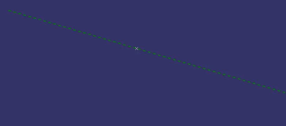
then draw a tooling axis as shown below.
DRAFT ANALYSIS:
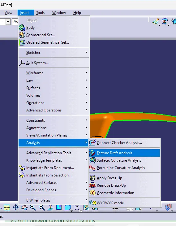
for draft analysis, in surface workbench click on insert>analysis>feature draft analysis as shown below:
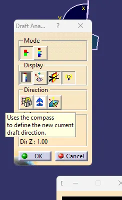
now click on compass to create c compass and place it on the tooling axis.
click on the class A surface to check the draft in the surface.
from the below figure it shows green which means it has a draft of more than three angle.
because less than three degree angle was difficult to manufacture.
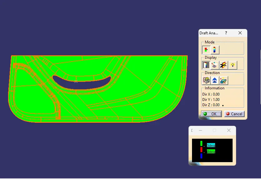
if the draft angle is less than three degree change the tooling axis angle or position and try it.
in this the degree of it is 3 something where it cant be cleared.
SURFACE B :
for creating a class b surface. first extract a plane surface and then untrim it. now extrapolate the untrim portion . then trim to get a final output. and offset it to a thickness of the component.
for this challenge, it is directly offset to the thickness of 2.5mm.
]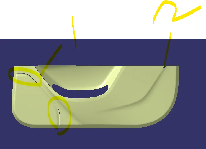
here only one patch is missing. it is cleared by using a blend, extrude,trim command it was cleared.
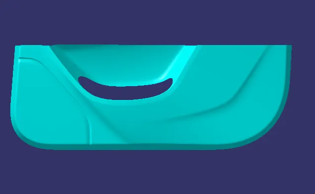
here it shows the CLASS B SURFACE.
note:
to check the clas B surface.create a boundary on it . if the booundary was along the corner it is perfect if not check it.
CLASS C surface:
creating a class c surface firstly create a boundary along the class a surface. then using a sweep command sweep it.
for this boundary two individual boundary are created and then join together.
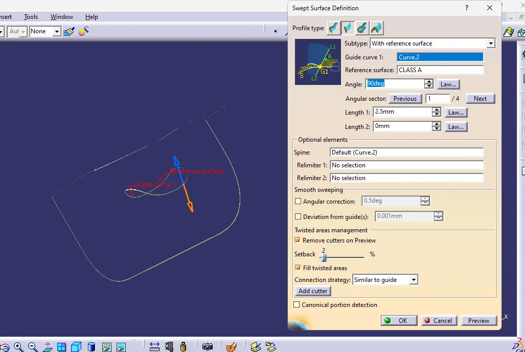
for surface parallel to tooling axis it is sweep with the referance surface.
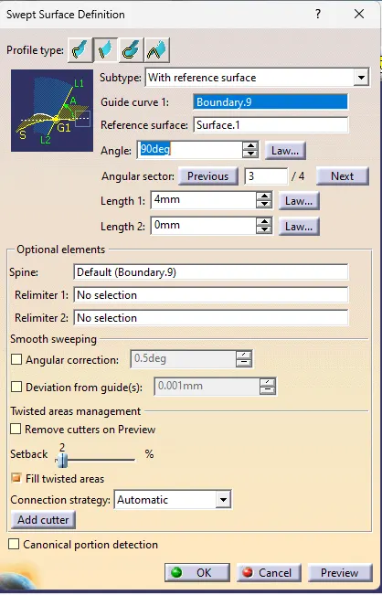
after sweep it is extruded and trim to obtain a joined surface.
after creating a class c surface. using a trim command join the CLASS A and CLASS C surface to get a joined surface as shown below.
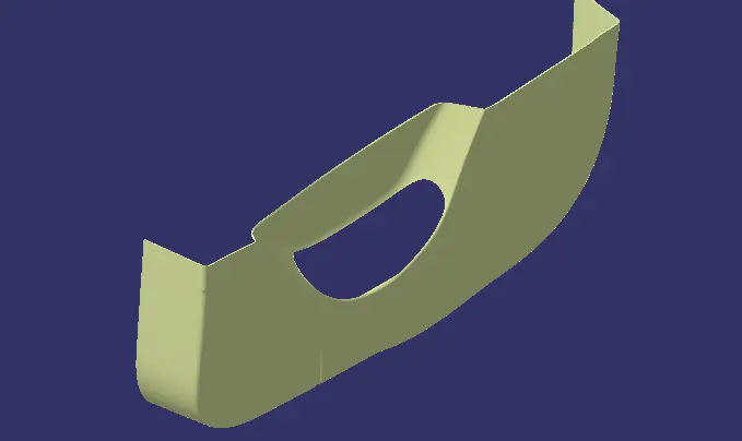
FINAL OUTPUT:
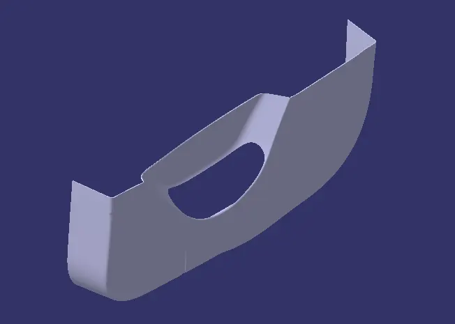
then trim the joined surface of A and C to the the classB surface to get a final output as shown below:
note:
create a boundary in the final trim. if it shows no boundary. then it is a closed surface.
else it has some open surface. patch it or fill the opens.
now, from the part design. create a solid body
FEATURE ATTACHMENT:
for locator and heat stake:
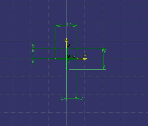
create a positioned sketch and draw the sketch as given below for a heat stake draw a concentric circle with 5 and 7mm.
then pad it to a 25mm. now copy and paste special with link the heat stake as many.
now using a point to point translation translate the pasted heat stake.
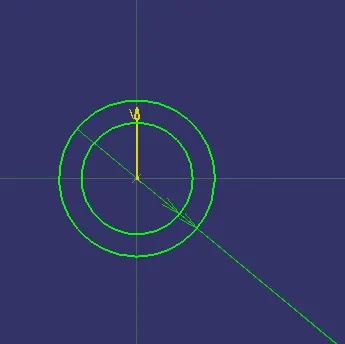
for creating a 4way locator. create a positioned sketch and draw two line with the centre as point.
then pad it and give entry chamfer and a edge filletof 3mm.
then copy and paste special with link the locator as many.
now using a point to point translation translate the pasted locator.
heat stake:
locator.
final output:
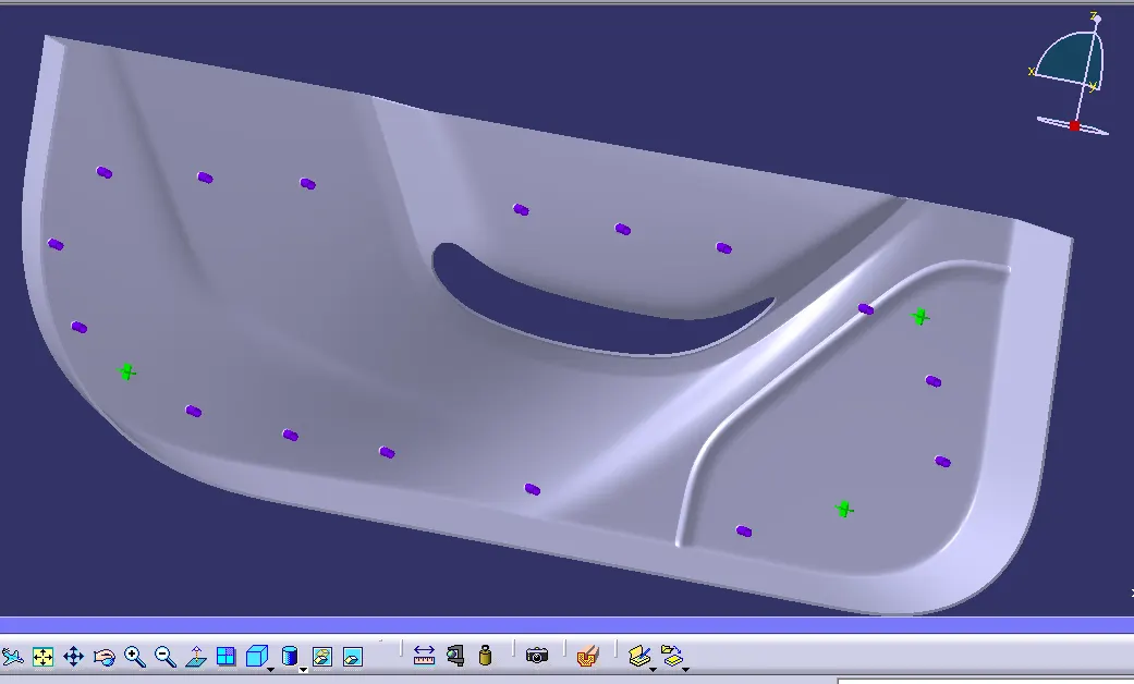
here the blue color shows the heat stake and green shows the locator.
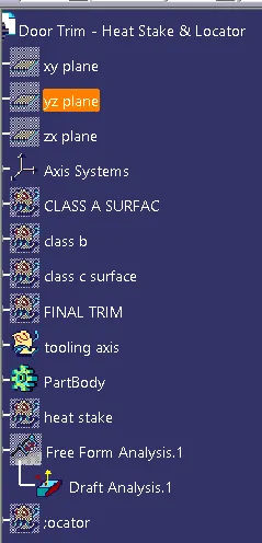
tree structure:
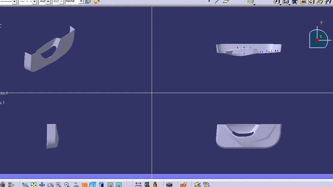
ALL views:
DRAFT ANALYSIS:
for draft analysis, in surface workbench click on insert>analysis>feature draft analysis as shown below:
now click on compass to create c compass and place it on the tooling axis.
click on the class A surface to check the draft in the surface.
from the below figure it shows green which means it has a draft of more than 1.5 degree angle.
for side core axis as a compass direction. it was obtained the below images.
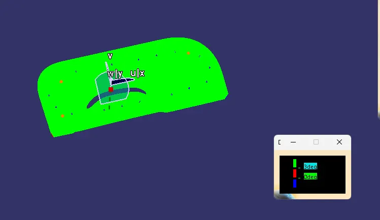
outer walls shows blue in color because it is ouside the side core axis with negative angle.
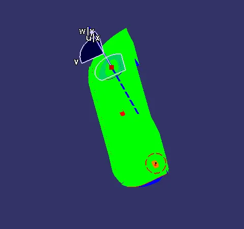
draft analysis for final component:
conclusion:
from the above, Created the door applique Plastic component, heat stake and locator was done through the given Class-A surface.
the catpart file is attached below.
==================================================================