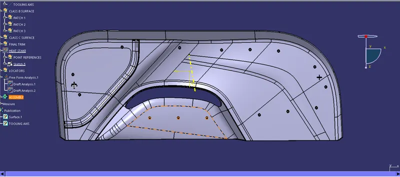
Week 10 - Challenge 3 - Door Trim Lower with Engineering Features
Door Trim Lower with Engineering Features
Create the Door Trim Lower Plastic component through the given Class-A surface. To begin with, the tooling axis for the given Class-A Surface should be created meeting the requirements of the draft angle and at the end perform the Draft analysis on the model.
Given CLASS A Surface
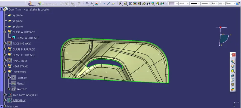
- Before proceeeding make sure there is no gaps in between the given Class A surface,visually we can check it or by clicking boundary command.
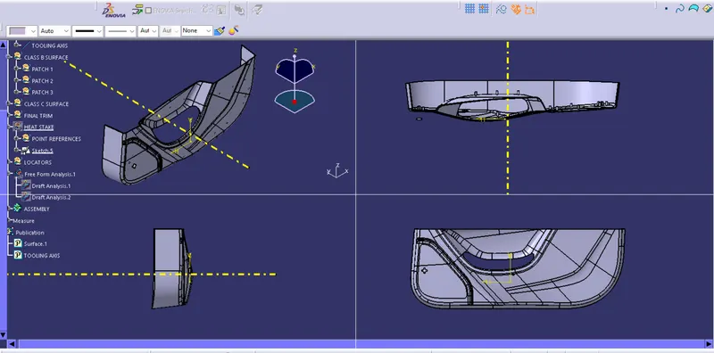
- Find the best possible tooling axis of the component. The tooling axis is the line which the mould or cavity opens.
- Look for the best possible tooling axis according to the product shape
- Check all three axis, Along Y and Z, it is not faesible.so X direction is the best possible direction for tooling axis.
Creating the tooling axis
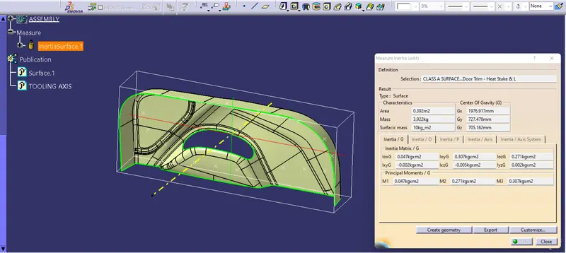
At first find the direction in which covers the maxiumum number of surface of the part and extract base surface of the part. Find the center of geometry of the part and through that point draw a line in the direction as we found earlier.
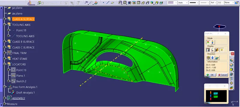
Draft analysis
Now perform the Draft analysis using the Featured Draft Analysis tool in the tools.
Then after opening the draft analysis tool box ,go for the compass and place the compass alinged to tooling axis, and click on the lock symbol to lock the position. after alinging click on the surface which we want to do draft analysis,minimum draft angle given is 3 degree.it shows green colour once its finished.
Creating Class B Surface:
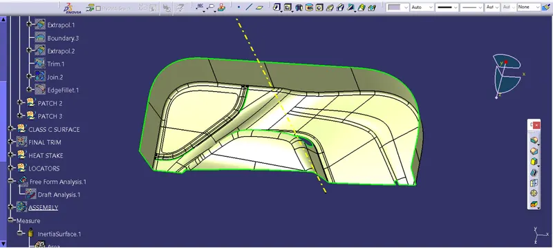
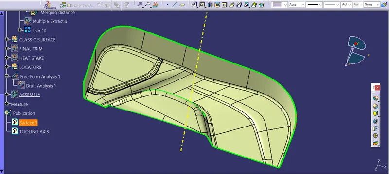
Before creating B surface,make an extract copy of given Class A surface,do an offset of Class A surface by using offset tool at a distance of 2.5mm ,after offseting some of the offseted surfaces may have missing surafces,that we need to work on it,using the join option for removing the discontinued surfaces and create new surfaces by using extrapolation tool,do the necessary trims.
Then trim the extra surfaces to get required surface.
Now apply fillet to required areas,consider to add thikness value to all fillets.
Offset surface (Before completing class B surface)
After completing the Class B surface
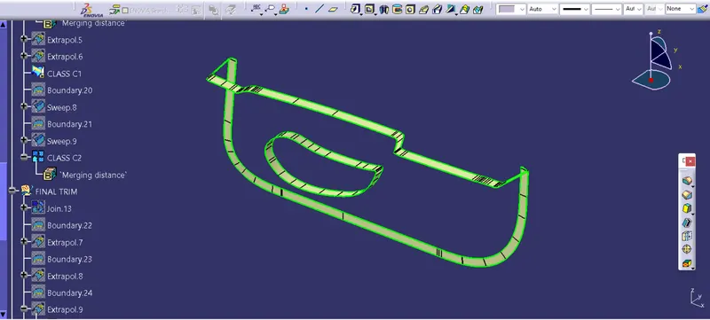
Class C Surface
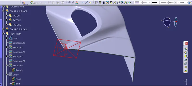
class C surface is made by extruding edges of class A through class B surface by swept tool,then do the trimming operation to remove unwanted surface
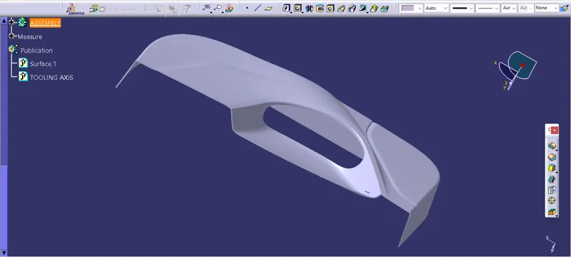
Closed Surface:
once class C is created join all the surfaces,we get closed surface,use boundary tool to check the part has any open profiles.
Then open part workbench,apply closed surface tool on the final surface we have created to get the solid body.
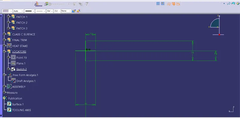
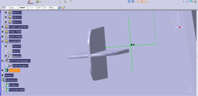
CREATION OF 4 WAY LOCATORS
After creating the sketch, pad it to 20mm height and thicken it to 1.3mm and drafted it to an angle of 0.5deg in the direction of the tooling axis.then gave 3mm length chamfer with 45deg of inclination,fillet the edge with 0.25 mm
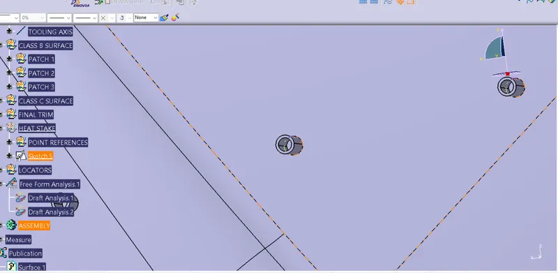
CREATION OF HEAT STAKES:
Draft analysis of final body
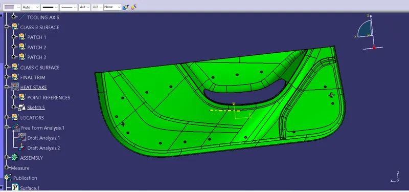
View from various orientations
Top view