Week 10 - Challenge 3 - Door Trim Lower with Engineering Features
DOOR TRIM LOWER
Aim:
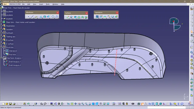
To Create the Door trim lower component with engineering features like Heat stakes and Locators through the given Class-A surface.
Objectives:
• Creation of Tooling axis.
• Creation of other surfaces (eg, B and C surfaces) for creating a solid component.
• Performing Draft analysis on Class A surface and Solid model which created.
Tooling Axis :
The class A is analyzed to create the tooling axis. Where the mold separates the two havles for injection moulding. Tooling direction is essential for plastic component as it decides the direction of mold separation.
To create tooling axis for the given Class A surface we should analyze the surface with the help of compass and identify in which plane it may satisfies. Actually bisecting method is used, but for time saving purpose we can use compas method for better results.Here Y direction satisfies the compass method. Then the extract of the door trim is taken and a point is subjected to the surface which is extracted, and a tooling line is drawn using the point and direction for tooling axis.
Draft Analysis:
For molded or cast parts, the draft angle is the amount of taper perpendicular to the parting line. It is measurable in degrees. Because plastic shrinks and sticks on molding surfaces as it cools, we draft the walls of the plastic component so that it ejects or breaks free from the molding surfaces more easily and without dragging. To reduce the risk of damage to the components and ensure ejection, a functional injection molding part must have drafts on both the cavity and core sides.
Nominal values for Draft angles
- 3 Degrees is a nominal draft angle.
- 5 Degrees can also be manufactured. Increasing the manufacturing cost.
- 7 Degrees is considered for Textured surface parts.
Importance of Draft in injection molding:
- Reduces the possibility of part damage due to friction during the release.
- Reduces mold wear and tear.
- Ensures a uniform, smooth, unscratched finish.
- Ensures the integrity and uniformity of other surface finishes and textures.
- Reduces overall cooling time by reducing or eliminating the need for unusual ejection setups.
Steps followed for Draft Analysis :
- After creating a tooling axis we do the draft analysis. Before drafting we have to make sure that in the view mode it is selected for the materials.
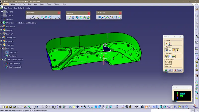
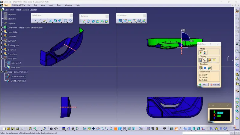
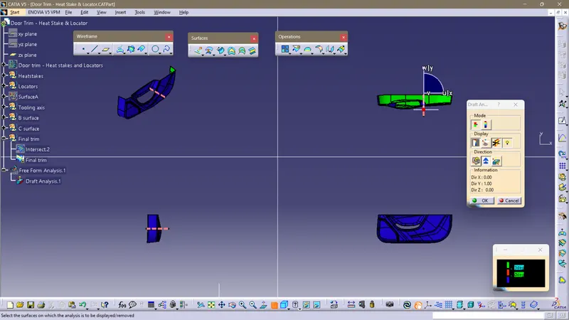
- After selecting the feature draft analysis tool we drag the compass from its position to the tool axis. Then lock the compass. After that select anywhere on the component and it will give you the result.
- We change the minimum draft for the component to 3°.
- We can use the running point option to check the angle of the component.
Class-B surface:
It is the offset surface of the Class A Surface the offset value depends on the thickness of the material, here the offset value is 2.5mm outward some of the surfaces give offset error and ask for offset without these subelements click okay and work on the incomplete surfaces by using the multi-section surface command, sweep and different commands used to complete the class B surface.Incomplete surface gaps in the offset, so we work on the surfaces and ensure that there is no gap in the class B surfaces.
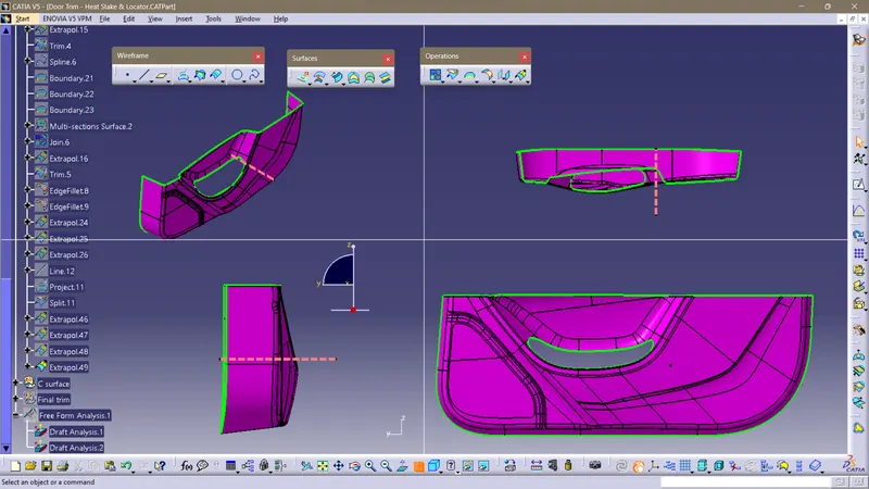
Class -C Surface :
We have to perform the sweep comand for the different boundaries and edges with sweep with draft reference as tooling axis with 3 degrees inside angle, then all the C surfaces created by using sweep comands are used to join with the join command.
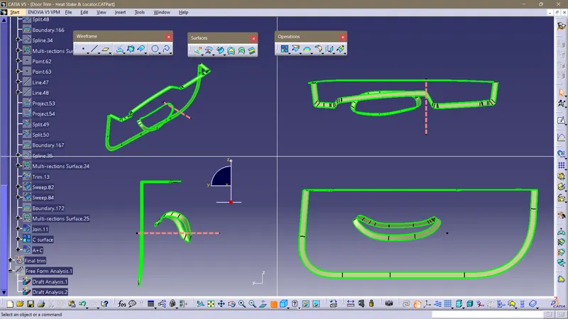
Class A+C :
The Surface A and the Surface C are used to join with each other for creation of closed surface.
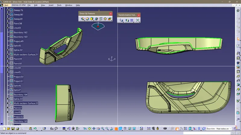
Final Trim:
After joining A and C, we then move forward and trim A+C from the class b. After the trim we can have a final complete surface of the door trim. After that the draft analysis is done for the final product.Completion of the draft analysis then we can have the closed surface toolbar in part model for creating a surface to part model.
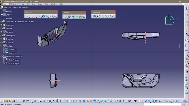
Locators :
Loactors are use to restrict the free movemnet of the trim to be placed in correct placement without any movement and transition. These locators also can used for guiding for the further operations to be done on the trim by not affecting the 3-2-1 Principle.
3-2-1 PRINCIPLE:
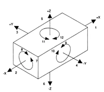
A work-piece free in space can move in an infinite number of directions. For analysis, this motion can be broken down into 12 directional movements or "degrees of freedom". All 12 degrees of freedom must be restricted to ensure proper referencing of a work-piece.
As shown in Fig 1, the 12 degrees of freedom all relate to the central axis of the work-piece. Notice the 6 axial degrees and 6 radial degrees of freedom. The axial degrees of freedom permit straight-line movement in both directions along the 3-principle axis shown as X, Y & Z. The radial degrees of freedom permit rotational movement, in both clockwise & counter clockwise radial directions around the same three axes.
*Degrees of Freedom of a Rigid Body
Consider the rigid body shown below which is situated in space. It can have 12 degrees of freedom.
Heat Staking :
Thermal staking is an assembly method that uses the controlled melting and reforming of a plastic stud or boss to capture or lock another plastic or metal component of an assembly. Manufacturing operations currently use many different types of assembly methods to keep components together. Common fasteners such as bolts, screws, and rivets can be used to form permanent attachments, but there are some assembly methods that don’t require secondary hardware. One of those methods is heat staking, that dont require any additional fasteners.
ADVANTAGES:
• Simplification of machinery
• Reduced cost of machinery
• Multiple fastening points
• Allows higher density of welds compared to hot air cold form or ultrasonic welding
• Many different size or shaped heads can be formed.
Guidelines for Heat staking for desinging:
- Very simple design guidelines are required for success of heat stakes. There are a number of factors that are essential in obtaining good Heat stakes. They are outside diameter, height, & geometry. The height of the heat stake should be less than the locator because the locator will locate the trim then the other operations will be continued perfectly and heat stake stud head dia. of approximately 1.5 – 3.0 times the outside diameter accordingly to the requirement of the plastic trim.