Week 10 - Challenge 3 - Door Trim Lower with Engineering Features
OBJECTIVE: Create the Door Trim Lower Plastic component through the given Class-A surface and create the Heat Stakes and the locators considering the design rules mentioned.
GIVEN CLASS A SURFACE:
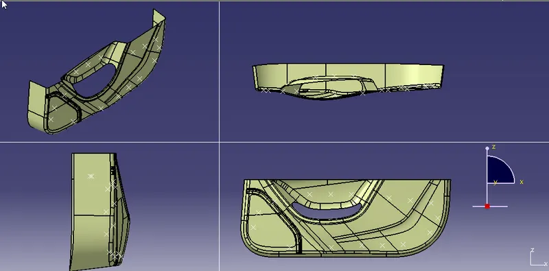
PROCEDURE FOLLOWED:
1. TOOLING AXIS CREATION:
The Tooling Direction is basically the direction that the mold pulls a part. The mold is built in two separate pieces, basically. You have a Cavity side and you have the Core side. The Core pulls apart from the Cavity and that's the Dye line or the Tooling Direction.
- Visually check the possible tooling direction .In this case y direction is the suitable tooling direction
- extract a surface from the classA find center point, with help of cordinant system draw intersection curve
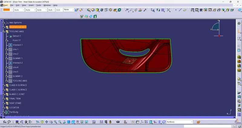
- Create an axis system and forn an intersection curve along yz plane.
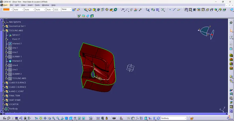
- an dummy axis created using bisecting line method
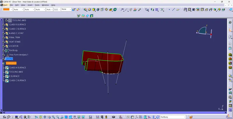
- create an intersection along xy plane .using the inter section curve create another dummy tooling axis
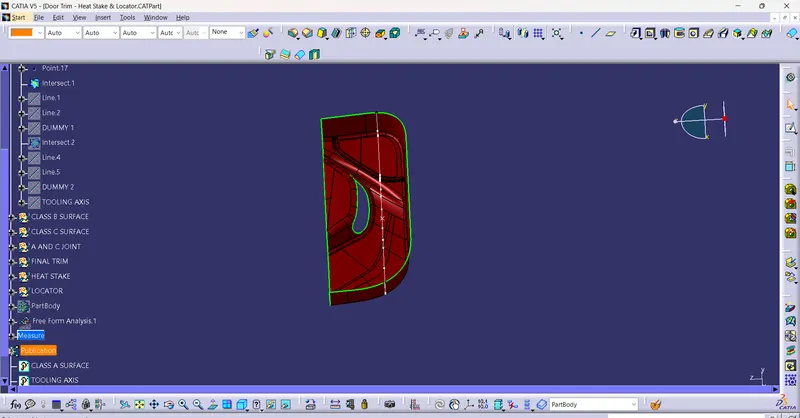
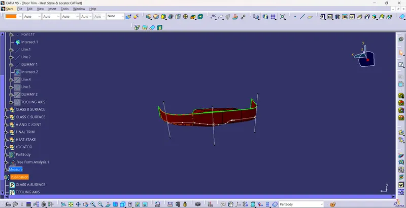
- using the 2 dummy tooling axis we create the main tooling axis by bisecting line method
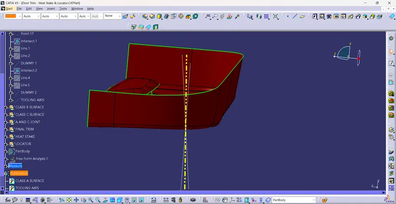
2.DRAFT ANALYSIS OF CLASS A SURFACE:
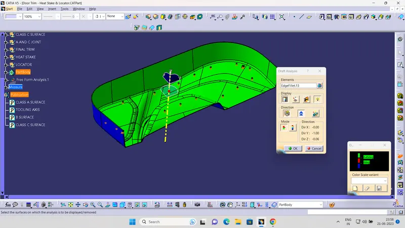
The draft angle is the amount of taper perpendicular to the parting line for molded or cast parts. It is measurable in degrees. Because plastic shrinks and sticks on molding surfaces as it cools, we draft the walls of the plastic part so that it ejects or breaks free from the molding surfaces more easily and without dragging. To reduce the risk of damage to the elements and ensure ejection, a functional injection molding part must have drafts on both the cavity and core sides.
PROCEDURE:
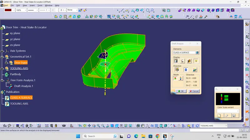
- First change the created part into material.
- Click on the compas and plase in the tooling direction.
- Use the lock command to fix the compass
- Click on the surface and apply the draft angle
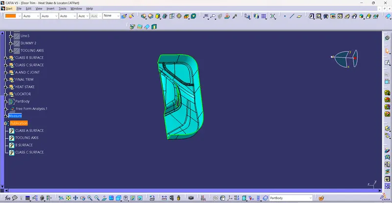
3. CLASS B SURFACE:
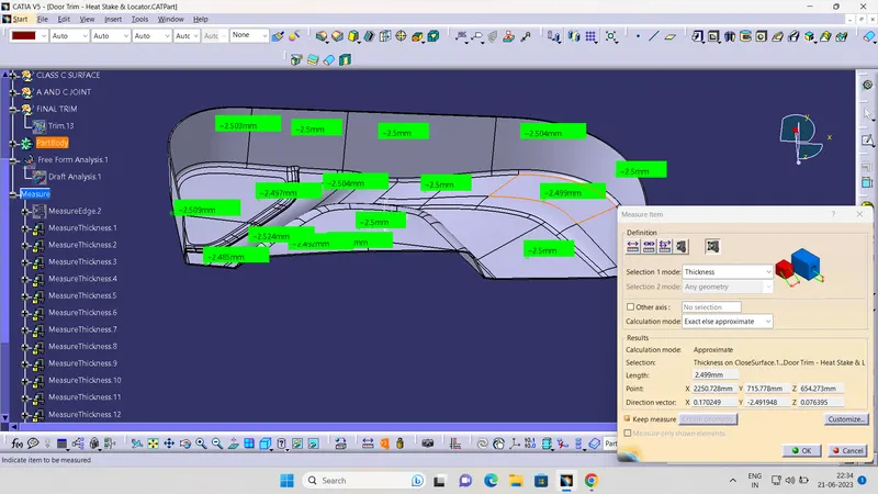
- The A-surface is offsetted by 2.5 mm as it is the thickness required.
- The Areas where the B-surface has issues are corrected by closing them using commands like Multi section,Extrude,Offset and extract.
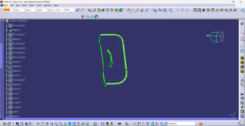
4. CLASS C SURFACE:
- The A and B surfaces are connected by another single surface which is called the C surface
- Class c is created using sweep command
- Here the sweep done in draft ditection and with reference to the surface.
- The portion not sweeping is connected using multiple surface tool
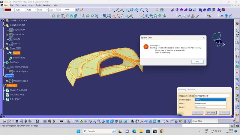
5. CREATION OF SOLID BODY:
- The solid body is created using close surface feature.
- Boundary is selected and the body is picked. Since an error popped up it can be understood that all surfaces are joined with each other to form a proper closed surface body.
6.HEAT STAKES CREATION:
These are projections or pertution provided to lock 2 panales togather by aplication of heat.
- create an plane normal to the tooling axis.
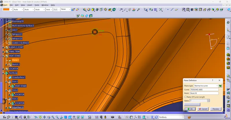
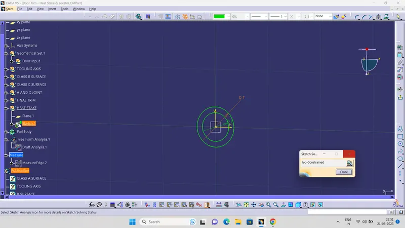
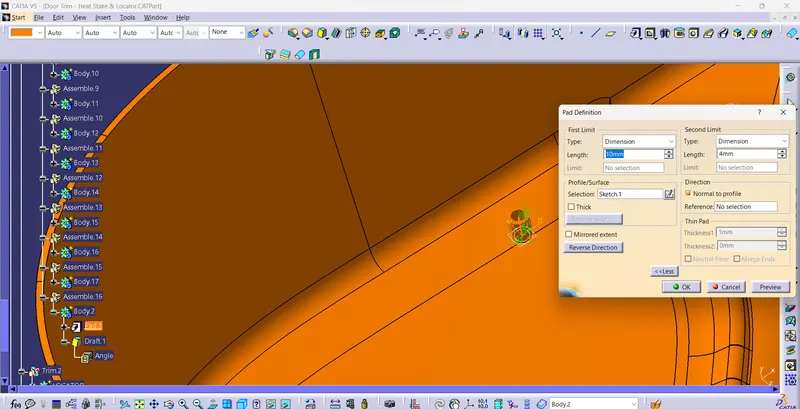
- After the drawing pad the sketch ,the height must be minumum 5mm below compared to the locator height.
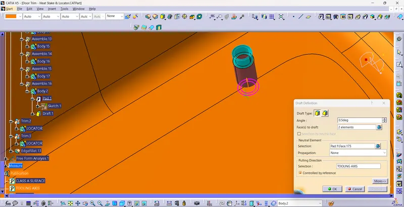
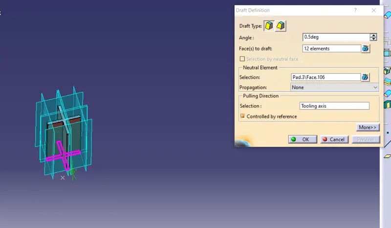
- provide drafof .5 degree.
- Copy the heat stack and paste speacial . With the help of transilation command transilate the body in every point.
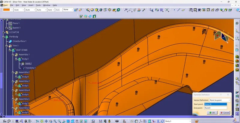
- With help of union trim connect these bodies.
7. LOCATOR CREATION:
-
create a point to add loactor projrction. postion sketch with plane as normal to draft direction
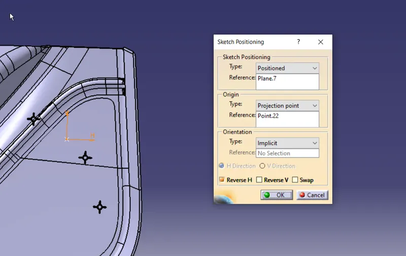
- Create the sketch for the locator
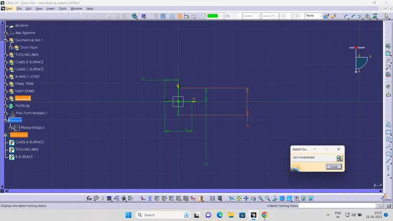
- pad the skectch and provide .5 degree draft
- provide fillet and campher
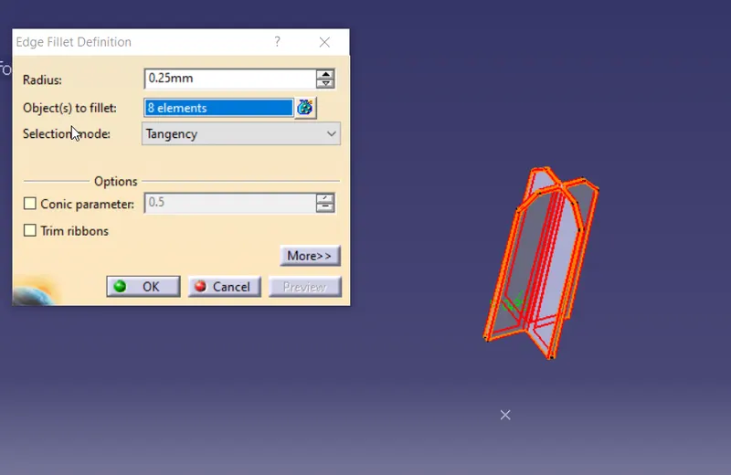
- Similarly copy the body and paste special.using transilation command place the body where ever we want.
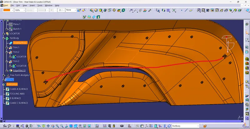
- Join the body with help of union trim.
8. DRAFT ANALYSIS OF FINAL BODY:
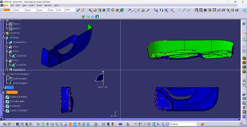
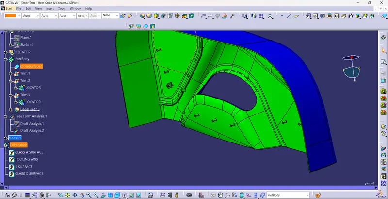
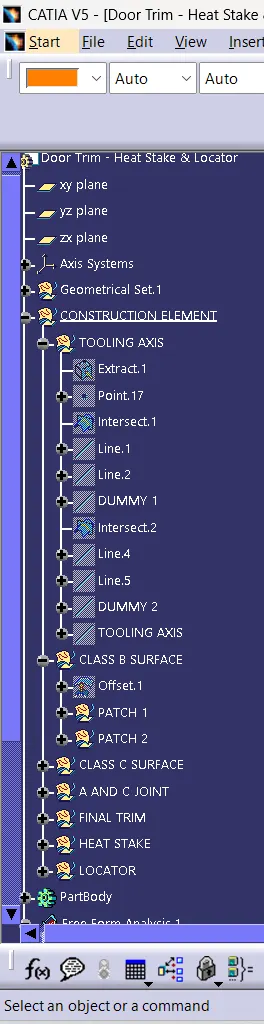
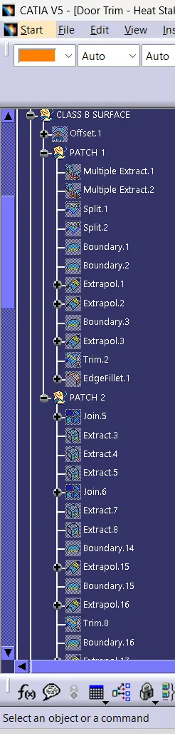
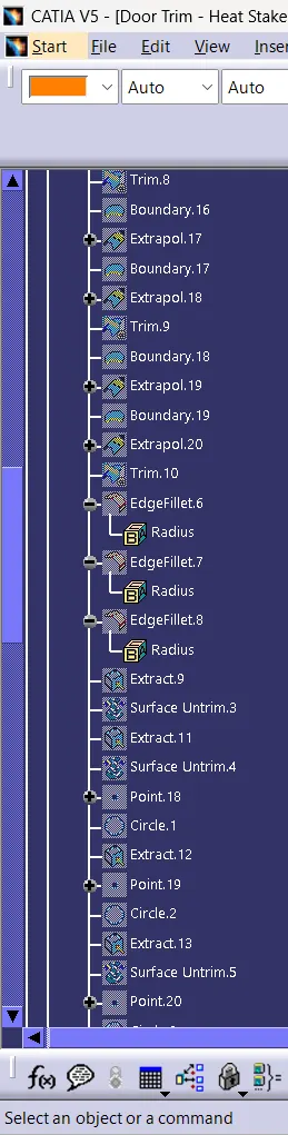
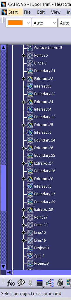
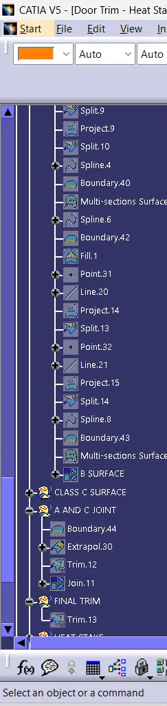
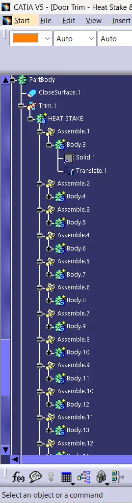
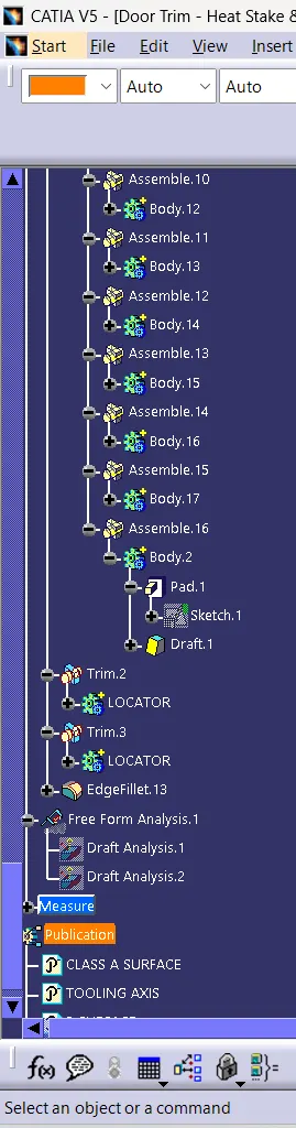
TREE STRUCTURE:
CONCLUSION:Created the Door Trim Lower Plastic component through the given Class-A surface and also created the Heat Stakes and the locators considering the design rules mentioned.