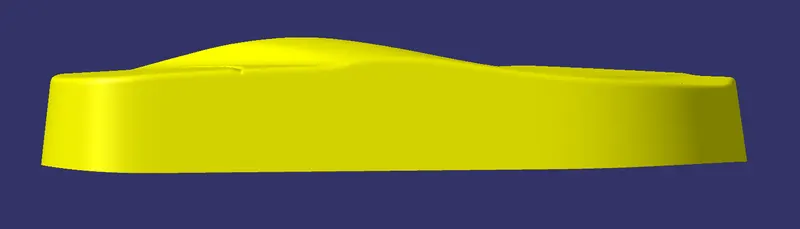
Week 10 - Challenge 3 - Door Trim Lower with Engineering Features
DOOR TRIM LOWER WITH ENGINEERING FEATURES
TOOLING AXIS CREATION
- for creating a tooling axis first we want to check the class a surface for a perfect tooling direction
- then create a point on the surface
- then create a line with point - direction method and project a line using axis direction perpendicular to the surface
- then check for draft analysis that the tooling axis clears the Class A surface
- in that test the tooling axis clears the class a surface and the tooling axis is usable and confirmed
- make that your main tooling axis and publish the Class A and Tooling axis
CLASS B SURFACE CREATION
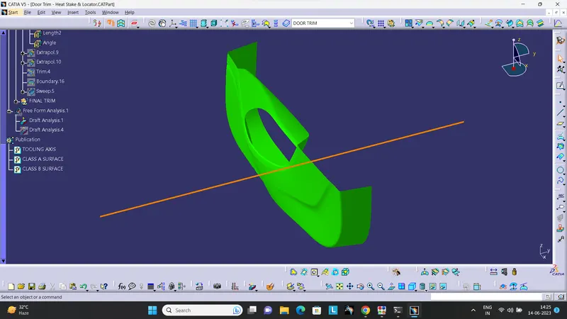
- after finalising the tooling axis add a geometrical set for Class B creation
- then offset the class A surface to 2.5mm inside
- Find out the patches that are missing from the class b surface offset
- and categorise them to 2 different geometrical sets
- for patch 1 remove the series of fillets that are missing from patch 1 using join command
- then extract the one unattached surface from the join and extract other
- extrapolate each of them using boundary command and when extrapolation extract a little more for the class c trim
- then trim those 2 extract and fix the patch 1
- same with the patch 2
- then find out the fillet values and add fillets to the B surface considering the offset value also
- that final filleted surface will be our class B surface
- extrapolate its boundaries a little more for class C trim
CLASS C SURFACE CREATION
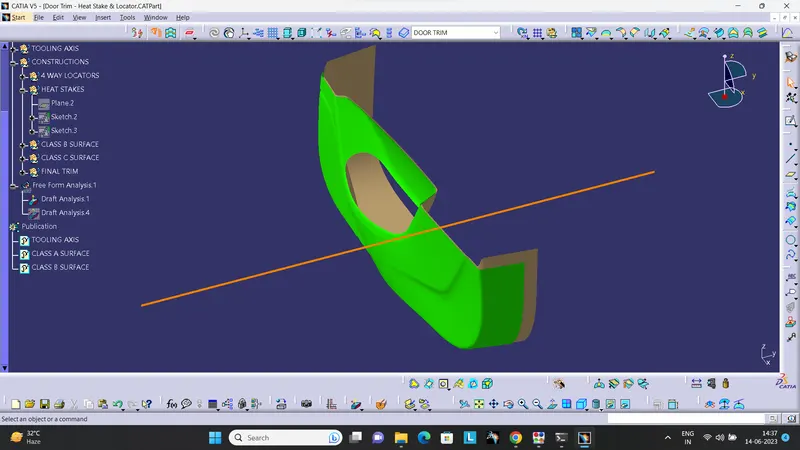
- select the boundaries of the class A surface and sweep that boundaries according to the ends of the surface ie, if the end of the surface is parellel to the tooling axis the sweep will be of 90 degree and sweep will be according to the reference surface
- if the end of the surface is perpendicular to the tooling axis the sweep will be according to the draft direction that is the guide curve will be boundary and draft direction will be tooling axis and the draft angle will be 3 degree outside direction
- when using sweep sweep to both top and bottom or front and back so that we can easily cut that with Class A surface

FINAL TRIM
- initially trim the Class C surface with the Class A (for that initially extrapolate the class a with point continuity which includes the hole and the outer boundaries
- extrapolate that to about a min of 3- 4 mm
- then trim that with the class C surface
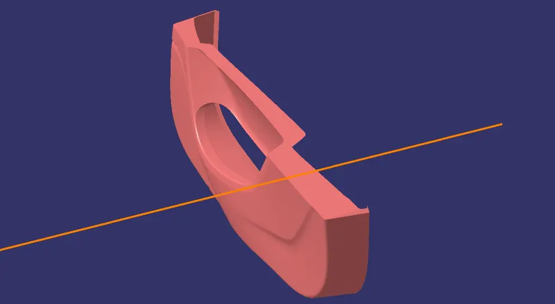
- then trim that with class B surface and get a closed surface
- check that the surface is closed or not with using boundary command or join
- in join it shows any error that will be a closed surface
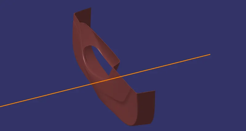
CLOSE SURFACE
- close the final trimmed surface with using part workbench and close surface operator
- close surface inside the partbody
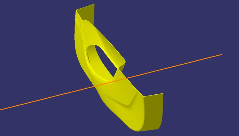
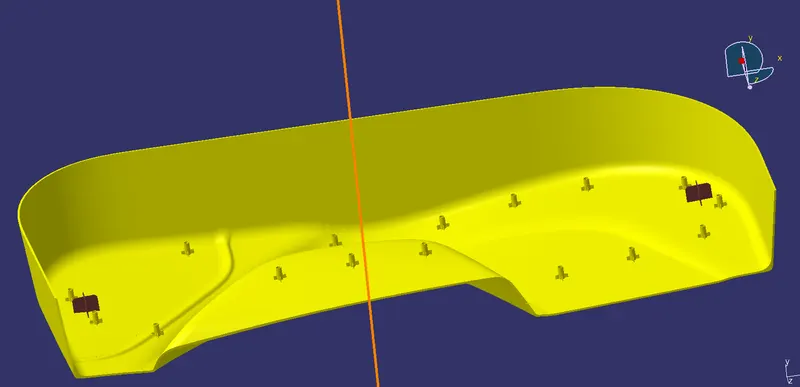
4 WAY LOCATORS
- add a new geometrical set for locators
- check for the locations for the locators from the question
- then mark points on the surface where we want locators
- make a plane on one point and add a positioned sketch wrt to the plane so created and projection point as the point so created
- then draw to like similar to that of the rib for the screw boss
- then pad it on a new body naming 4 Way locator 1 using thick option and neutral fibre with a value of 1.3mm
- then add chamfer on the 4 side edges with 3mm distance and 45 degree angle
- then add fillets to that edges
- then add respective draft of every face with draft angle 0.5 deg with its base as neutral plane and tooling axis as pulling direction
- then add fillets on every faces
- then copy the whole body and paste it on the project as paste special with attachment as a link then translate that to the other point that we had created before and rename it to 4 way locator 2
- then assemble that 2 bodies into a new body named 4 way locators
- then trim that with the main part body and remove the extrusion on the class A surface

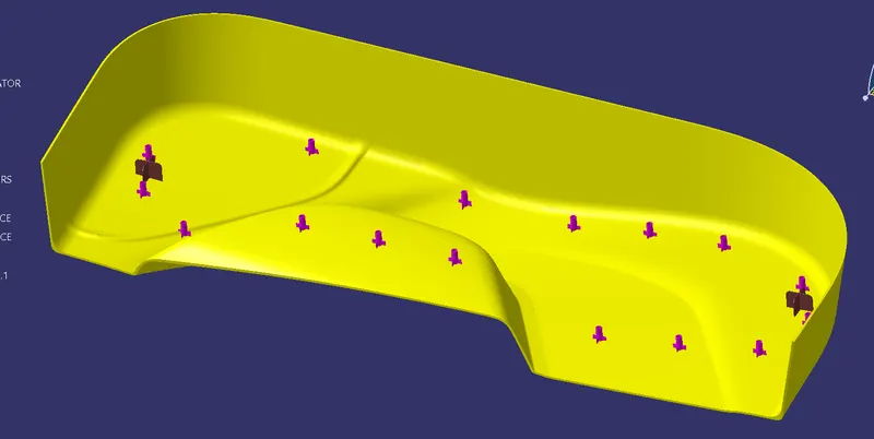
HEAT STAKES
- from the input point select a point and make a plane on a point
- then add a positioned sketch with the plane and projection point as the input point
- the draw 2 circle of dia 7 and 5mm
- then pad it on a new body with height less than that of the locators
- draft the body inside and outside with base as neutral element and tooling axis as pulling direction with an angle of 0.5 deg
- then add a new sketch on geometrical set of heat stake for rib and add required dimensions for the rib
- pad it to height that is less than the heat stake about 3:1 on a new body
- draft the all sides of the rib wrt to its base and tooling axis with an angle of 0.5 deg
- then trim the rib with base and remove the inside portion
- then name that body HS 1
- then copy and paste special as like the 4 way locators for 16 times to fill all the points
- then translate that to the specific point by input and assemble these on a new body named HEAT STAKE
- then trim that with the main body and remove any extensions present in the class a surface

FINAL DRAFT ANALYSIS
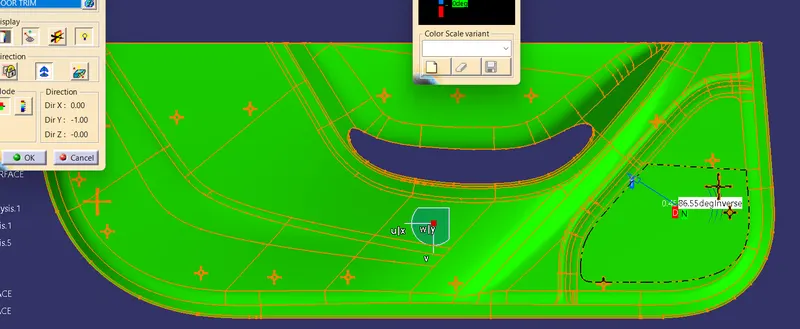
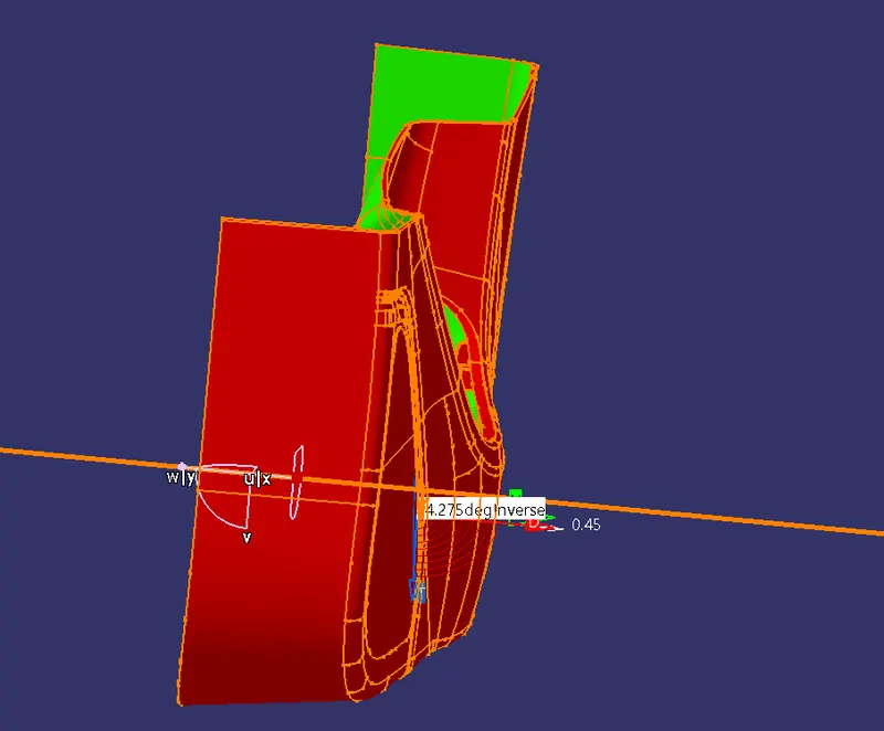
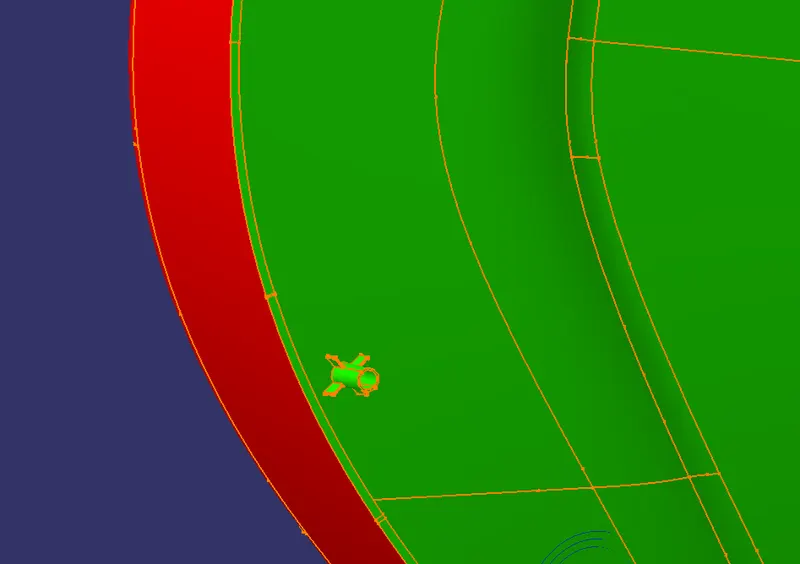
- do the final draft analysis for the final body wrt to the tooling axis
- drag the compass on to tooling axis
- click on the anchor and drag that once more to the tooling axis
- change the green value to 0.45 deg
DIFFERENT 3D VIEWS
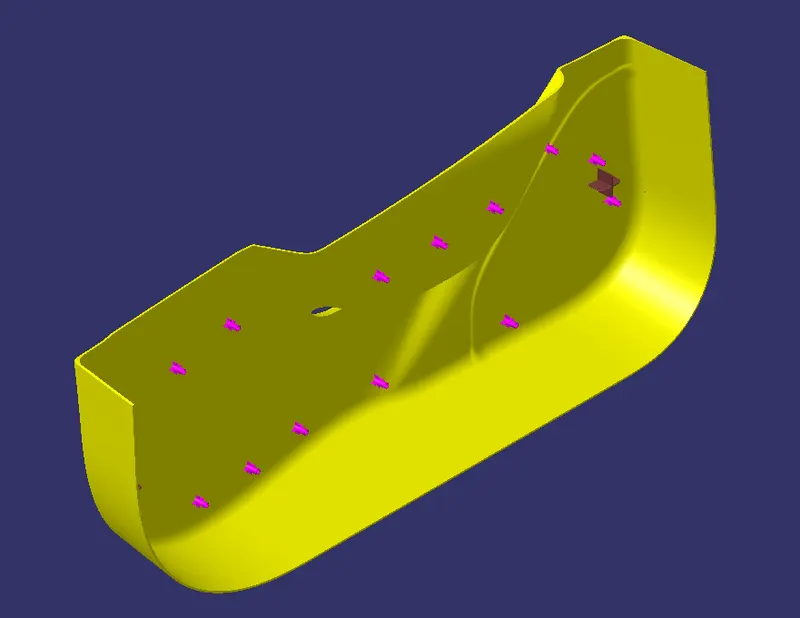
ISOMETRIC
FRONT
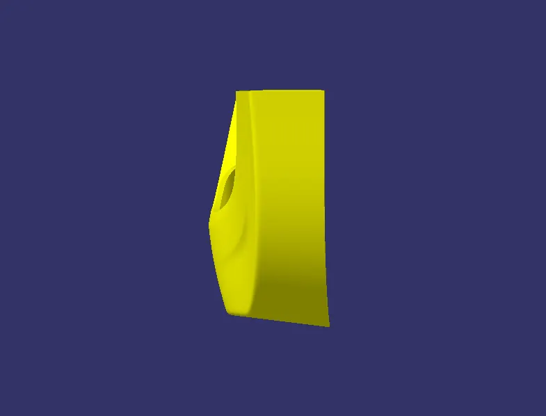
BACK
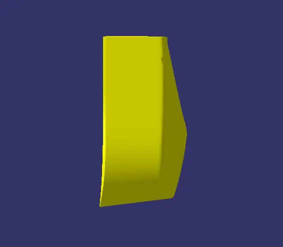
LEFT SIDE
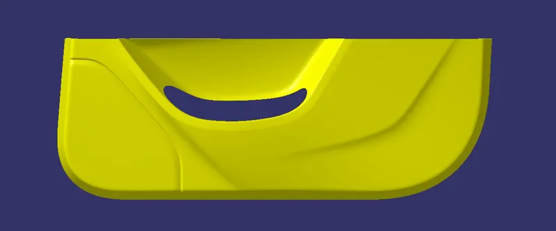
RIGHT SIDE
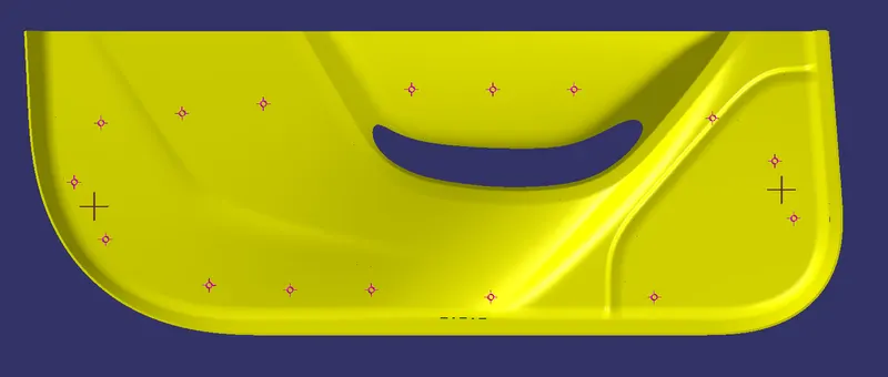
TOP SIDE
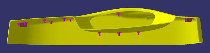
BOTTOM SIDE