Week 10 - Challenge 3 - Door Trim Lower with Engineering Features
TOOLING AXIS:
To create the tooling axis, I extracted a surface from class A and created a point in the middle of the surface by using the point command and created a line at that point through the x-axis. Now, I performed a draft analysis check from that line whether the created tooling axis is in the correct position or not. If in the draft, analysis check the surface highlighted with green colour on both sides of the surface the tooling axis is in the correct position and direction.
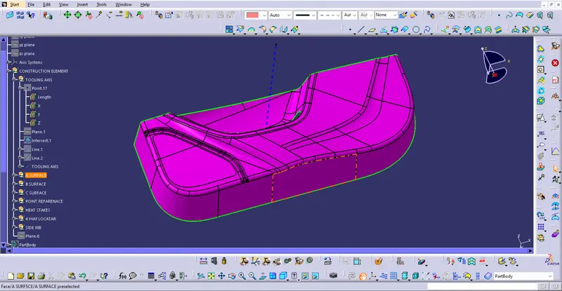
Creating a Tooling axis
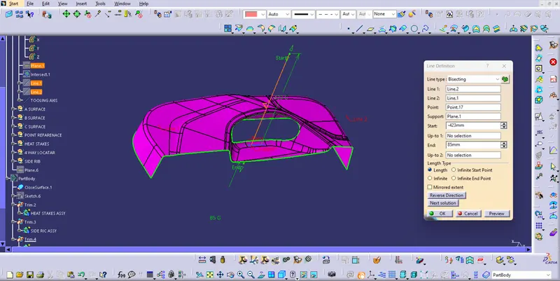
DRAFT ANALYSIS FOR CLASS A SURFACE:
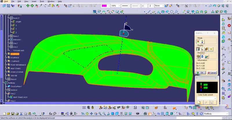
We do perform the draft analysis check for class A surface before we make solid and creation of B-side features. Initially I align the compass to the tooling axis and I gave a 3deg draft angle for the green colour in the colour bar. If the surface is highlighted in green colour the draft angle is given properly for class A surface. If the class A surface is not highlighted fully in green colour, that might be the reason for the draft angle of the class A surface.
1.Once the tooling axis is obtained, we conduct draft analysis on the class A surface with the help of tooling axis. This helps in determining weather the tooling axis we created is right or wrong.
2.Click on the draft analysis option.
3.Click on the compass icon and place the compass on the tooling axis.
4.Click anywhwere on the surface to generate the analysis result.
5.From the result it is clear that the surface has passed the draft analysis test
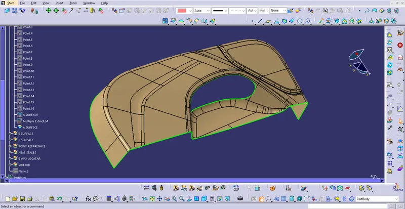
Given Class A Surface:
Before proceeed make sure there is no gaps in between the given Class A surface,visually we can check it or by clicking boundary command.Find the best possible tooling axis of the component. The tooling axis is the line which the mould or cavity opens.Look for the best possible tooling axis according to the product shapeCheck all three axis, Along Y and Z, it is not faesible.so X direction is the best possible direction for tooling axis.
Creating Class B Surface:
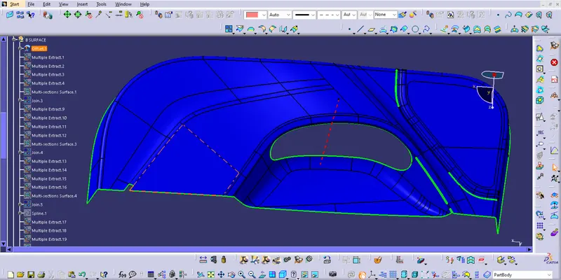
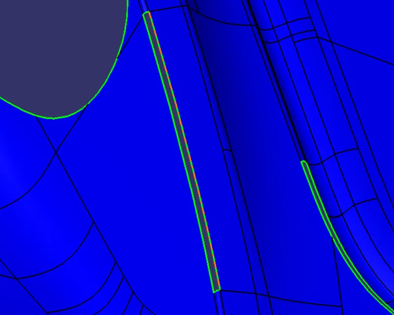
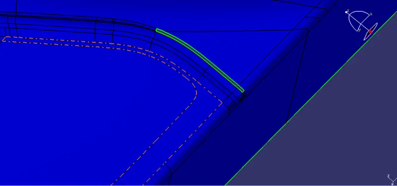
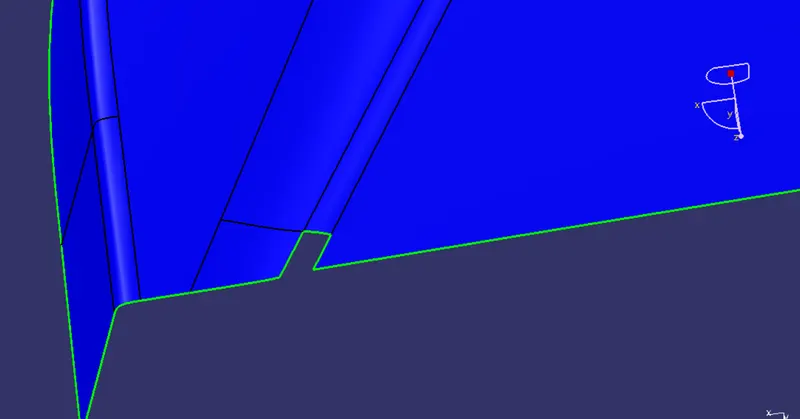
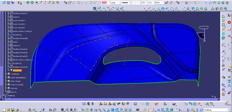
OFFSETTED CLASS B SUFACE WITH COMPLETING PATCH OPERATIONS :
- Offset the class a surface 2.5mm direclty.
- Some patches will form after offsetting.
- Remove the filleted region for closing the patches.
- Define the boundary and extrapolate to required length.
- Now trim the surfaces to required surfaces
- Now provide proper fillet the surface to required amount
Patch-1:
Patch-2:
Patch-3:
Patch-4:
Class B Surface:
CLASS C SURFACE:
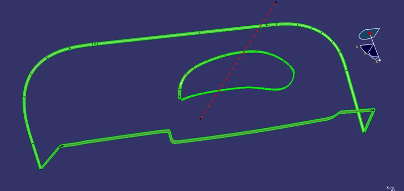
I used the sweep command to create the class C surface concerning the boundary of the class A surface. Initially, I extracted the boundary of the class A surface with tangent continuity, and I sweep the extracted boundary concerning the surface at 93deg (for draft angle) for 4mm to intersect properly with the class B surface. Once we sweep all the surface boundaries of class A, extrapolate the sweeped surfaces until both surfaces got intersect properly, and trim them to remove extended extrapolated surfaces to get a proper sweep boundary throughout the entire surface, including the centre hole of the door trim. Now, join both class A and sweep boundary to get the complete class C surface.
Class C surface:
Now, unhide the class B and class C surfaces. Check whether all the sides of class B and Class C surfaces are intersecting properly with each other, to get a closed surface by trimming class B and class C surfaces. If the class B and class C sides are not intersected properly, we need to extrapolate the sides of the class B surface which are not intersecting with the class C surface. Now, check class B and class C surface boundaries to see whether all the sides are intersecting or not with each other. Once the surfaces are intersecting properly trim them together to get a closed surface.
A+B+C SURFACE:
1.First join Class A with both the C surfaces.
2.Then using trim option, trim the A+C surface with B
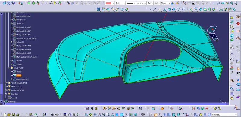
Closed Body:
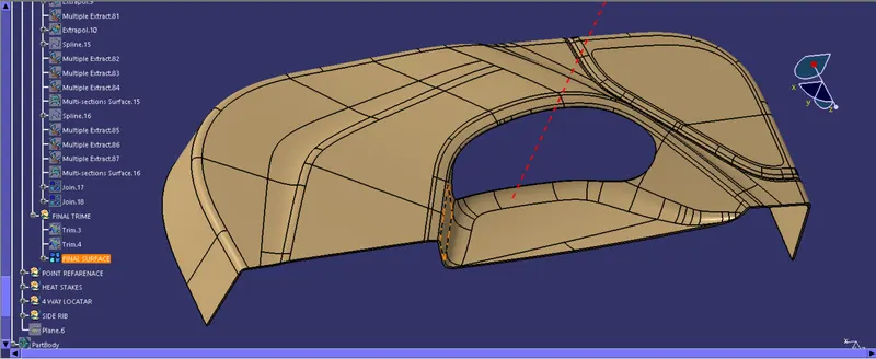
Closed Surface:
SOLID OF 2.5MM THICKNESS
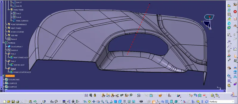
once class C is created join all the surfaces,we get closed surface,use boundary tool to check the part has any open profiles.
CREATION OF LOCATORS
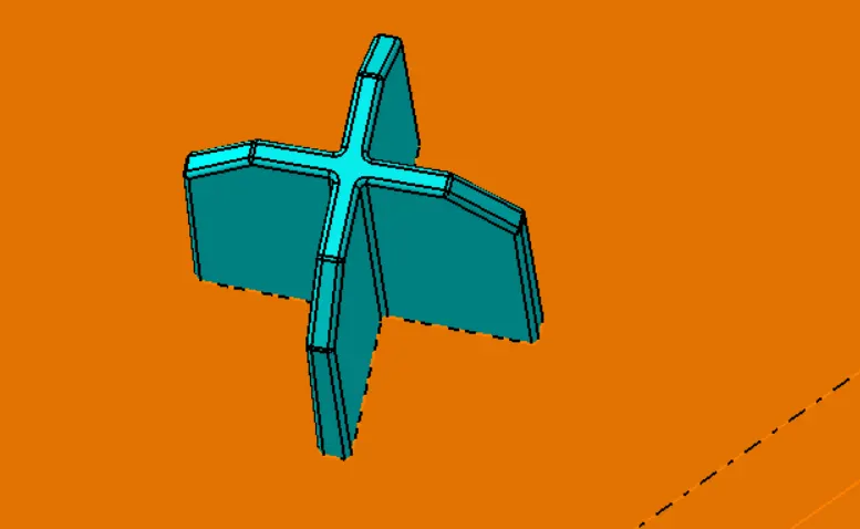
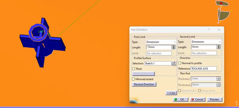
To create the locators, I created a sketch on the body. After creating the sketch, I pad it 20mm in height and thicken it to 1.3mm and I drafted it with 0.5deg in the direction of the tooling axis. I gave 3mm of chamfer with 45deg of inclination and after I gave a fillet of 0.3mm radius.
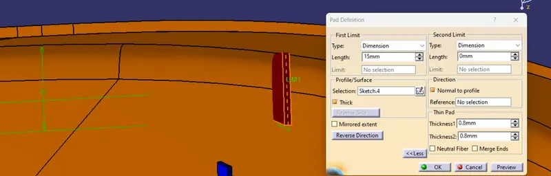
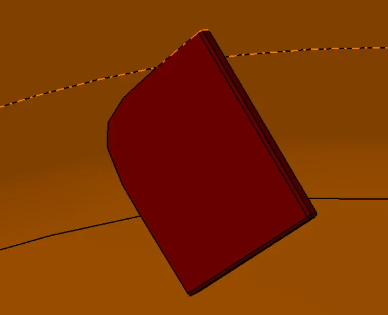
SIBE RIB :
4-way locator:
Heat staking:
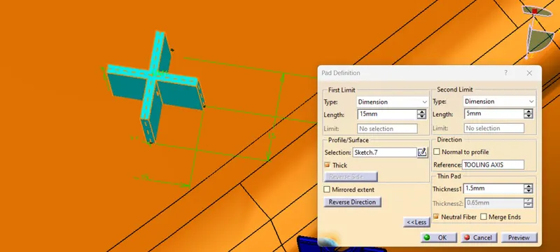
Heat Staking is a pulsed-heat process to join two or more parts out of which one at least is made of plastic. The process is to deform
the plastic material using heat and force at a set process time. The bond is made by partially de-forming the plastic part in order to
fix the other. Heat Staking makes it easy to bond metal to plastic and is commonly used in high volume/low cost applications such
as automotive, IT and consumer appliances.
Shaping Plastic Using Heat and Pressure:
The plastic is deformed by heating it to a temperature above the glass transition temperature. Super-heated air or a thermode is
used for this. Pressure is then applied to create the stake. After the stake has been formed, the plastic should be cooled down again
below the glass transition temperature. Cooling is performed under constant pressure to ensure good fixation of the parts.
Compressed air can be applied for cooling when a thermode is used. Heat is used to facilitate the creation of the stake. Heat control
is critical, especially for glass-filled plastics which often have a process window of less than 10 degrees Celsius. When the
temperature is too high, the glass fibres come out of the plastic which leads to a rough surface and adhesion to the thermode. If the
temperature is too low, the plastic will crack due to cold deformation.
Heat staking Benefits:
1. Similar and dissimilar materials may be joined: metal to metal, plastic to plastic, metal to plastic
2. Accurate control operating within a small process window
3. Local heating resulting in no damage to surrounding materials
4. Processing of glass-filled materials
5. No mechanical vibration
6. Many heat-stake shapes possible through custom designed tools
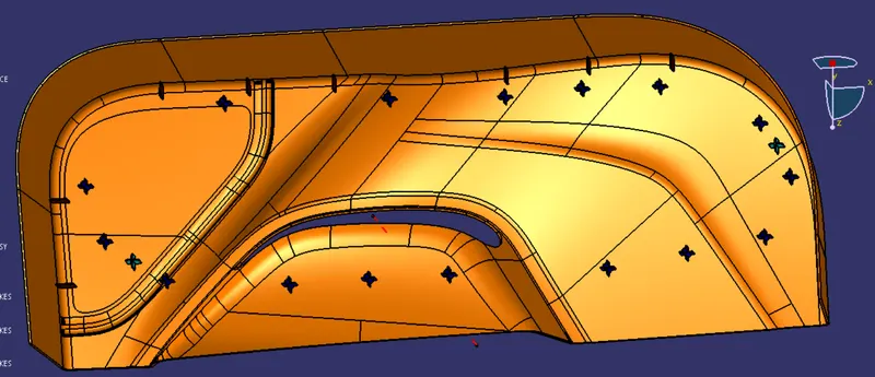
Door Trim Lower with Engineering Features LOCATOR & HEAT STAKE:
DRAFT ANALYSIS FOR PART BODY:
Draft analysis for Heat stakes and Locators:
The draft angle for heat stakes and locators is 0.5deg, so I gave 0.48deg in the colour bar for green to check whether all the surfaces are drafted properly or not.
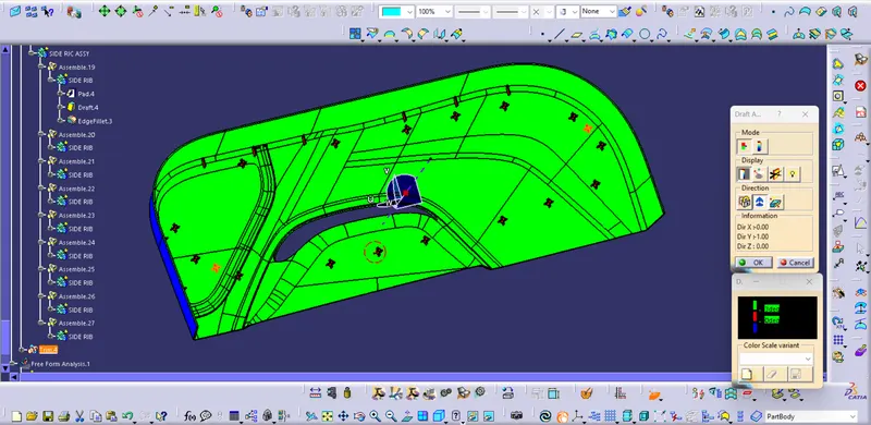
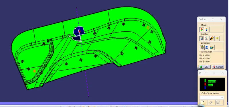
Some faces are not cleared properly, this is due to the curvature and inclinations on the class A surface.
The below-given images visualize the surfaces which are not cleared properly with a 3deg draft angle
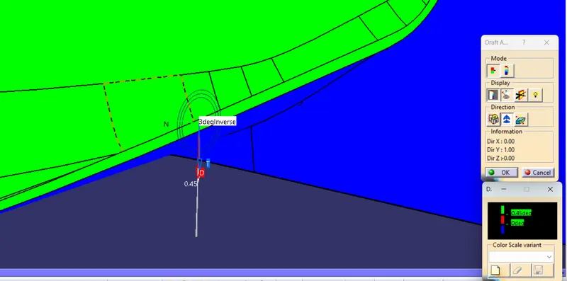
The below-given image is mostly tilted toward the class A side, which is the reason for the highlighting in green colour.
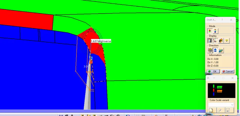
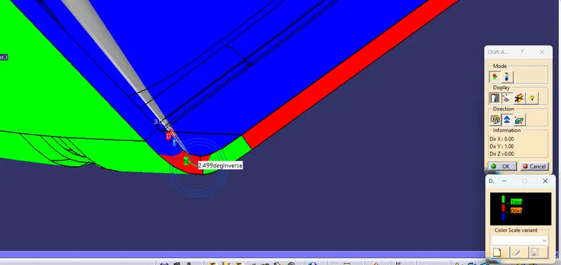
CONCLUSIONS
Successfully created Door trim plastic component , performed draft analysis for class a surface and solid close surface. Extracted closed solid body from plastic surface.
Created the ribs and Screw bosses for the Door Trim Lower considering the design rules , the Heat stakes and locators for the Door Trim Lower considering the design rules , the Dog house for the Door Trim Lower considering the design rules.