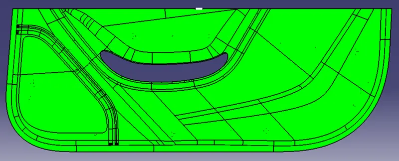
Week 10 - Challenge 3 - Door Trim Lower with Engineering Features
Door Trim Lower with Engineering Features
Draft Analysis:
The draft analysis tool used to analyse the feasibility of the CAD model for manufacturing. With the help of this tool, we can determine the available draft in the CAD model is sufficient or not. Proper draft will help to easier ejection of the part from the tool and whereas insufficient draft will end ends up in multiple tooling and part quality issue.
Drafts can be measured in mm/mm or in degree.
Types of Draft:
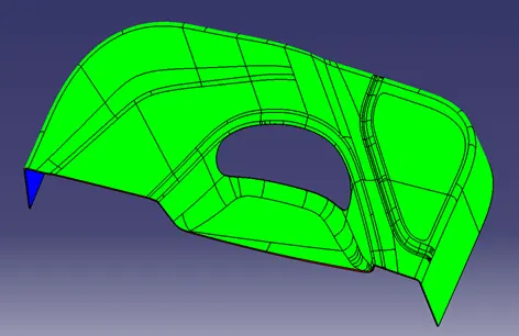
Positive draft:
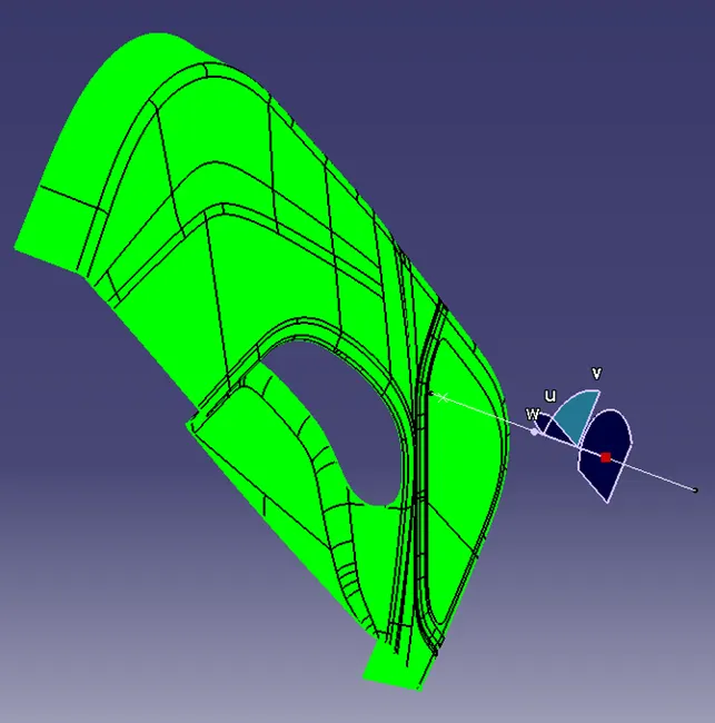
A positive draft means the angle of the face, with respect to the direction of pull, is more than the reference angle. In the below image you can see the Cad Model in the green colour, which represent as a positive draft in Catia.
Negative draft:
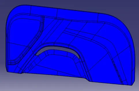
Displays any faces with a negative draft, based on the reference draft angle you specified.
In the below mentioned image the Cad model is been appeared in Blue colour which represent as a negative draft.
Why Draft?
Draft angles are a required feature of injection-molded custom parts. A functional part for injection molding has to have draft angles that face both the cavity and core sides. This will reduce the risk of damage to the parts and ensure that they can be ejected from the machine.
Without any taper, not only will the part come out scratched, but also the mold will endure unwanted wear and tear. This will in turn shorten the life of the tool. On top of all of this, you may not be able to eject the part in this case, meaning you’ll have to grind production to a halt to manually peel the part out of the mold.
- Minimizes the warping to your geometry
- Increases the tool life of the mold
- Improves the surface finish on your plastic parts
- Cuts down costs by reducing the cooling time
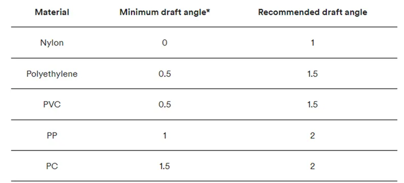
Draft Angle for different Injection Molded Components:
Bisecting Method:
This method is very helpful for symmetrical surface, it’s can be used for other profiles as well but easier with symmetrical surface.
Steps:
Insert the Class A Cad Model in Catia Application.
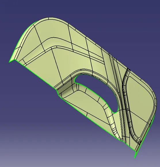
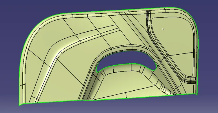
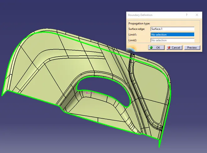
Perform the surface quality check, using the boundry comand. Make sure there is no open surface, if its there it will be Highlighted in the Green Line.
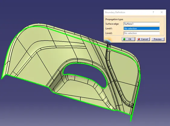
Once the Surface quality check completed, select multiple surfaces and make them normal to ensure that from that normal view entire part is visible.
For Bisecting Method, select those surface which can me symmetry from any plan and imaginary axis.
Once after deciding the surface, Go to the point option, select the between option.
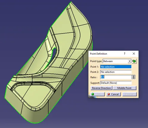
Select the two point from the reference of the Cad Model and select the two points and choose the middle point.
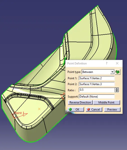
Once the point is been made, make the two line from the reference of the Cad Model.
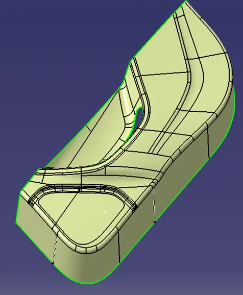
Remove the Cad Model and then the points and line will be visible for further reference.
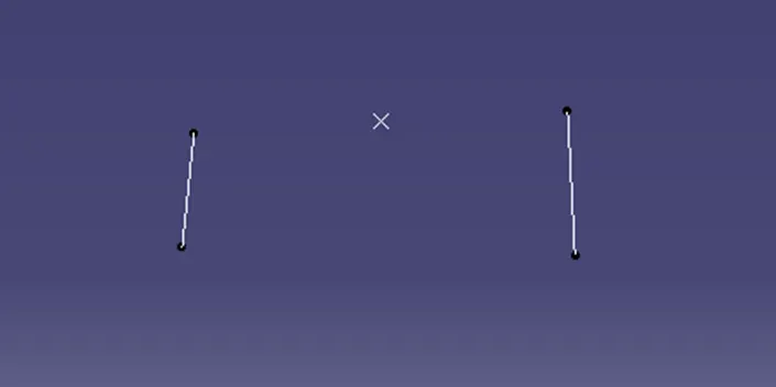
Go to the line option, select the Bisection method for line creation.
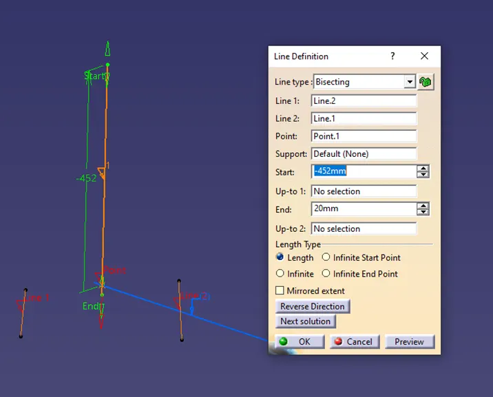
Once the tooling axis is been made on the Class A Surface. Select the tooling Axis and select the normal option.
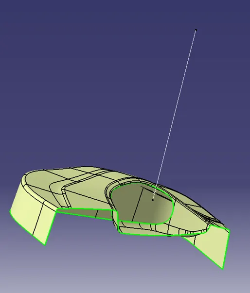
Adding Draft Analysis:
Select the Insert from the toolbar, select the Analysis and feature draft analysis.
Insert  Analysis Feature Draft Analysis
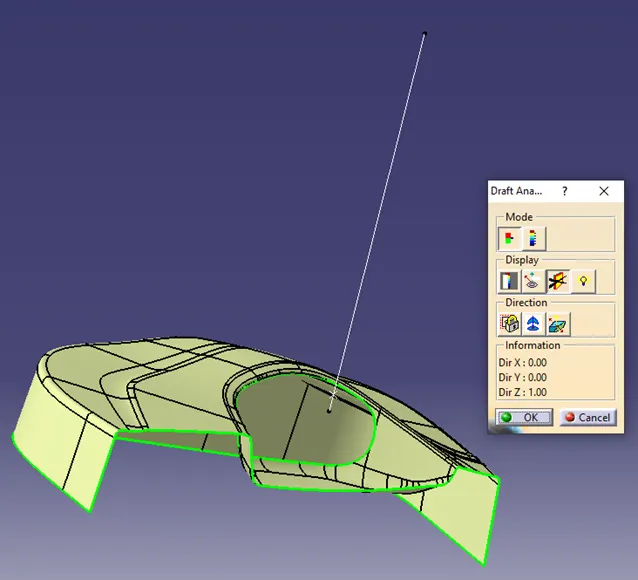
Align the compass over the tooling axis and enable the current draft direction.
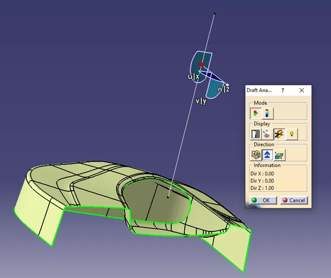
Once after enabling the current draft direction. Select the compass and reselect the tooling axis and select the part to see the draft analysis result.
Normal to Surface Method:
By name it-self is self-explaining that the tooling axis will be made with the reference of a surface along which the tooling axis will be passed.
Insert the Class A Cad Model in Catia Application.
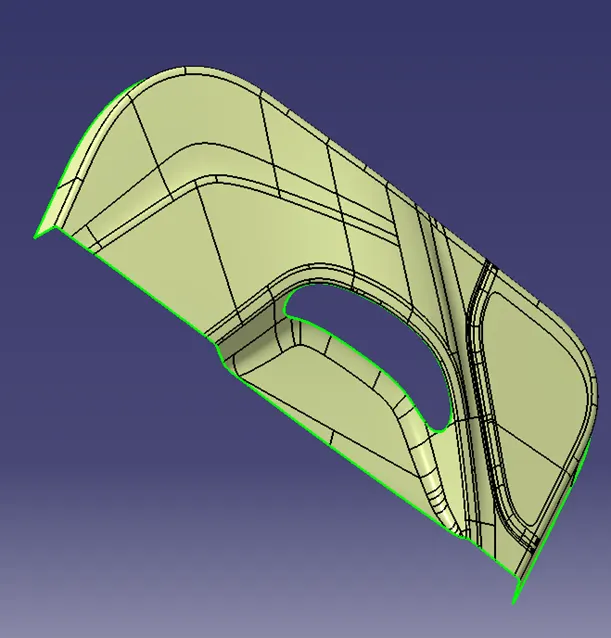
Perform the surface quality check, using the boundry comand. Make sure there is no open surface, if its there it will be Highlighted in the Green Line.
Surface Selection:
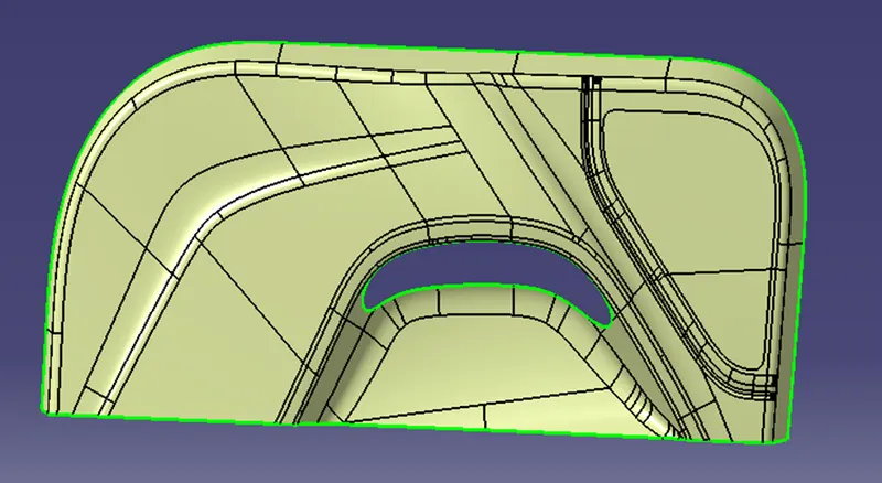
Once we receive the Class A surface from surface modelling team, we will look for a plane or surface along which we can see the entire surface of a model is clearly visible. But it generally take multiple trial to finalise the surface for tooling axis
Usage of compass will help us to finalize the surface.
Extract the Surface:
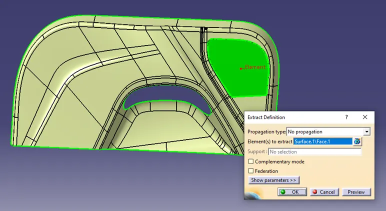
Here we will select a surface, while making it normal we can see the entire surface of the CAD model and extract as a indepenent surface.
Making a point on surface:
Once surface has been extracted the point need to be make on the surface along which the axis has to be passed.
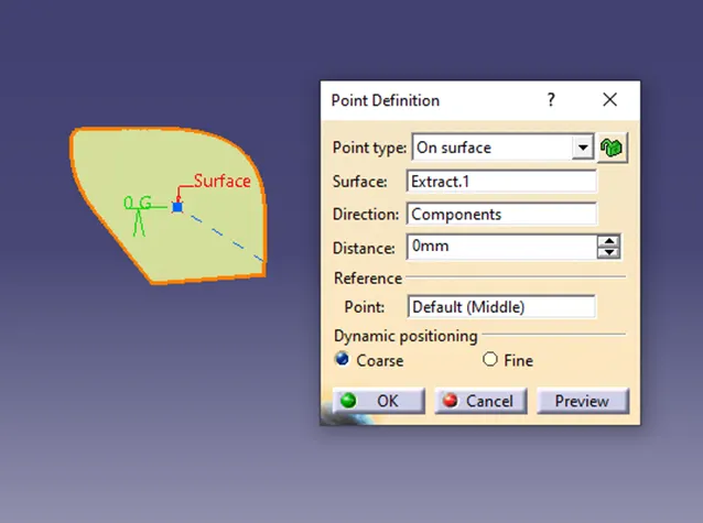
Line normal to surface:
Once the point has been made on the surface, make a line on the surface, selecting the normal to surface option.
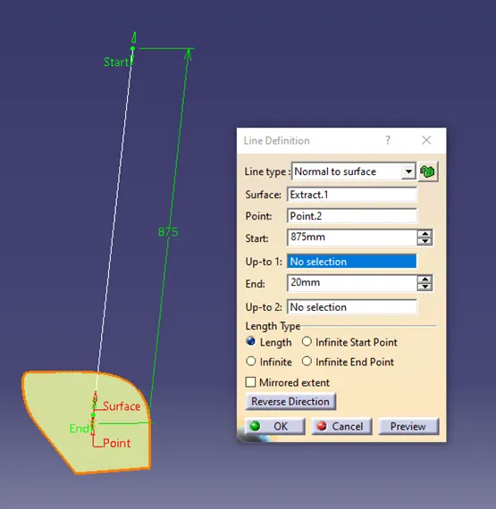
Adding Draft Analysis:
Select the Insert from the toolbar, select the Analysis and feature draft analysis.
Insert Analysis Feature Draft Analysis
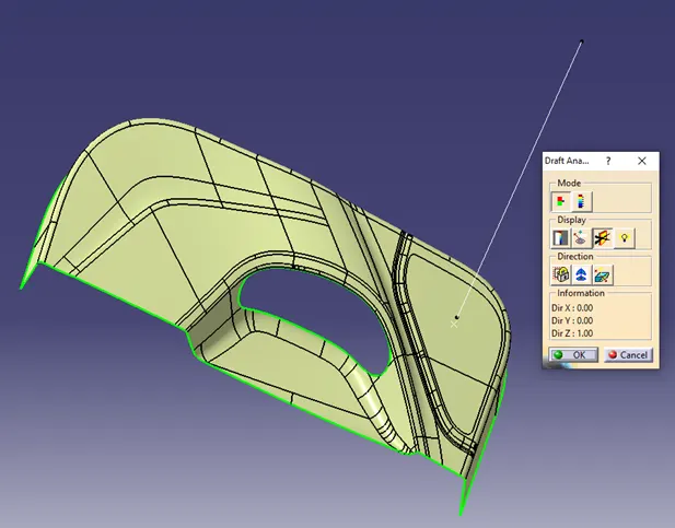
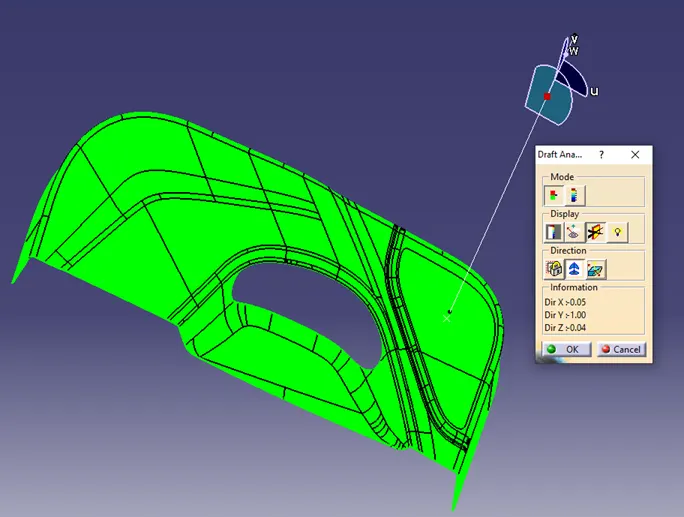
Creating Heat Stakes
Heat stakes are specialized devices used in various industries for joining or fastening two or more materials together. They are particularly useful for applications where traditional fastening methods such as screws or rivets are not suitable or practical.
Heat stakes are typically made of plastic and are designed to be heat-formed or melted into a parent material, creating a secure and permanent bond. The process involves heating the stake to its melting point and then inserting it into a pre-drilled hole or cavity in the parent material. As the stake cools and solidifies, it creates a strong mechanical connection.
These stakes are commonly used in industries such as automotive manufacturing, electronics, and plastics. They are often employed for fastening plastic components, such as attaching connectors, brackets, or other parts to a main structure.
Advantages of using heat stakes include:
- Cost-effective: Heat stakes can provide a cost-effective fastening solution compared to other methods like adhesive bonding or mechanical fasteners.
- Design flexibility: They allow for greater design flexibility as they can be placed in areas where traditional fasteners might be difficult to use.
- Quick assembly: Heat staking can be a relatively fast process, especially when automated equipment is used.
- Enhanced strength: Heat stakes can create strong bonds with the parent material, providing mechanical strength and durability.
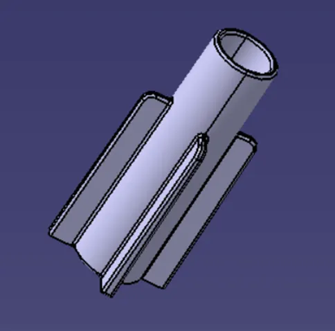
Heat stakes Design Dimensions
ID: 5mm
OD: 7mm
Height: 20mm
Rib Length and Width: 12mm
Draft: 0.5°
Height: 12mm
Fillet: 0.25mm
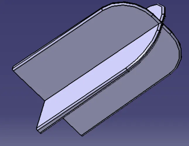
Locator Design Dimension
Rib Length and Width: 12mm
Height: 16mm
Draft: 0.5°
Fillet: 0.25mm
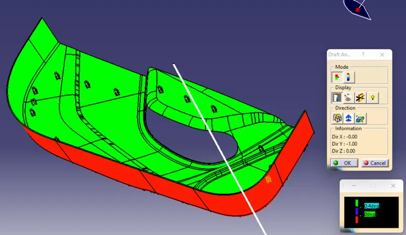
Final Draft Analysis:
To analyse the draft analysis for heat stakes and locators the draft specification changed to 0.4 degree in order to measure the draft of 0.5° available on heat stakes and locators.
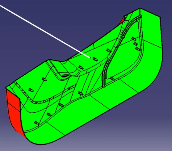
Different Views:
Isometric View
Top View
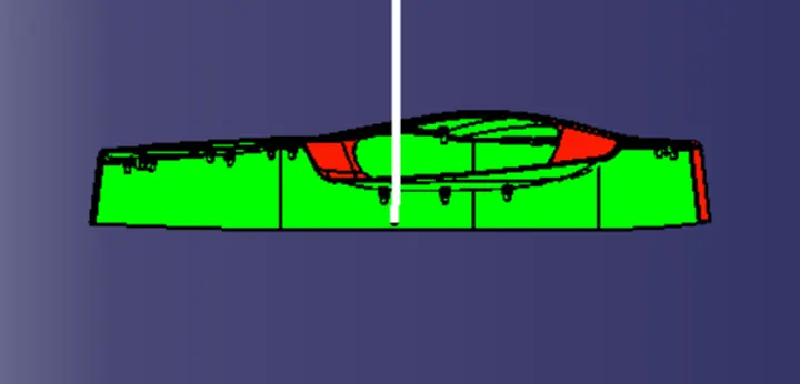
Front View
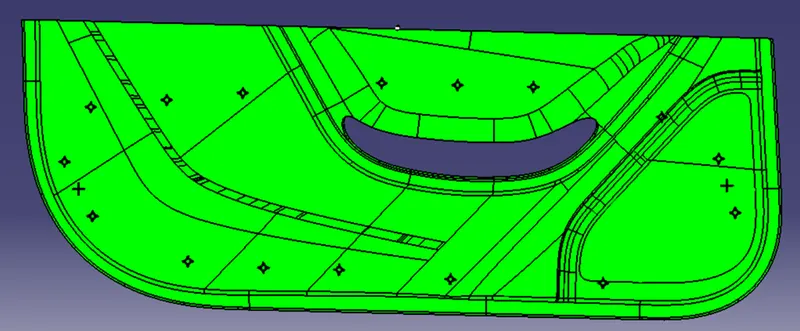
Side View