Week 10 - Challenge 3 - Door Trim Lower with Engineering Features
Door Trim Lower with Engineering Features design heat stakes and the locator's design considering the design rules.
AIM: Create the Door Trim Lower Plastic component through the given Class-A surface. To begin with, the tooling axis for the given Class-A Surface should be created meeting the draft angle requirements and performing the draft analysis on the model at the end.
Design the Heat Stakes and the locators considering the design rules.
Class A surface:
This is the styling surface that provides the aesthetic features of a component. A designer starts the design of component by given class A surface.
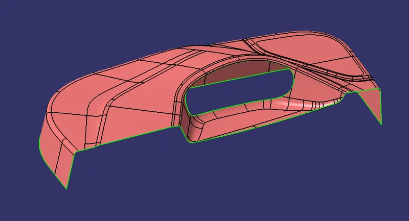
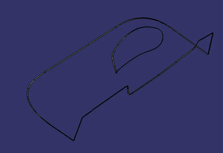
The initial step is to check for any discontinuity in the class A surface model using Join or Boundary option. Here only the outer boundary line is found. There is no discontinuity between the surfaces. The next step is to define the tooling direction.
TOOLING AXIS CREATION
Tooling direction has to be the direction in which most of the features can be easily cleared. To create the tooling axis first we have to check the best suitable direction for tooling by using the compass. the y direction is suitable for creating the tolling axis because in the y direction most of the surfaces are clearing while performing draft analysis. Generally tooling axis is created using bisecting line method but here A line normal to the surface is created in the y direction and considered the tooling axis.
In injection molding, the Class A surface is first analyzed to determine the axis or tooling direction that separates the molds. Tooling direction is critical for plastic product design because it determines mold direction
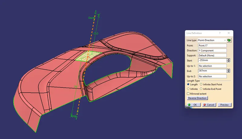
DRAFT ANALYSIS FOR CLASS A SURFACE
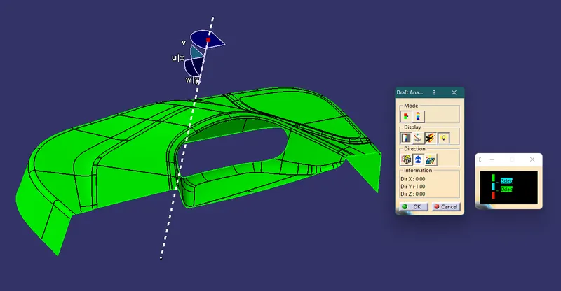
We do perform the draft analysis check for class A surface before we make solid and creation of B-side features. After creating a tooling axis we do the draft analysis.
Before drafting we have to make sure that in the view mode it is selected for the materials.
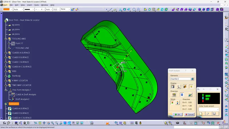
After selecting the feature draft analysis tool we drag the compass from its position to the tool axis. Then lock the compass. After that select anywhere on the component and it will give you the result.
We change the minimum draft for the component to 3°.
We can use the running point option to check the angle of the component.
Importance of Draft in injection molding
- Reduces the possibility of part damage due to friction during the release.
- Reduces mold wear and tear.
- Ensures a uniform, smooth, unscratched finish.
- Ensures the integrity and uniformity of other surface finishes and textures.
- Reduces overall cooling time by reducing or eliminating the need for unusual ejection setups.
CLASS B SURFACE
To create a class B surface class A surface is offset to 2.5mm and we have to work on the patches by using the multisection or sweep features if required 2.5mm is the thickness of the component
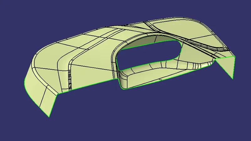
CLASS C SURFACE CREATION
Class C is nothing but connecting part of Class A & B. Unhide class A and takes the boundary of it and now boundary selects all corner of class A and uses sweep commands to create class c surface.
Joining class A surface and class c surface together first
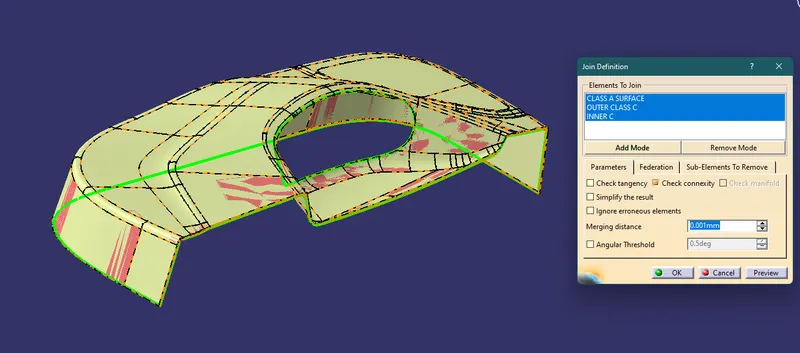
Then trim the class-B surface to join (A+C) this will make sure that we get a closed surface. We can check it using the boundary tool, if it gives an error that means that the component is closed.
Then We go to the part design workbench and use to closed surface tool to create a solid body.
hence, we created our final plastic component.
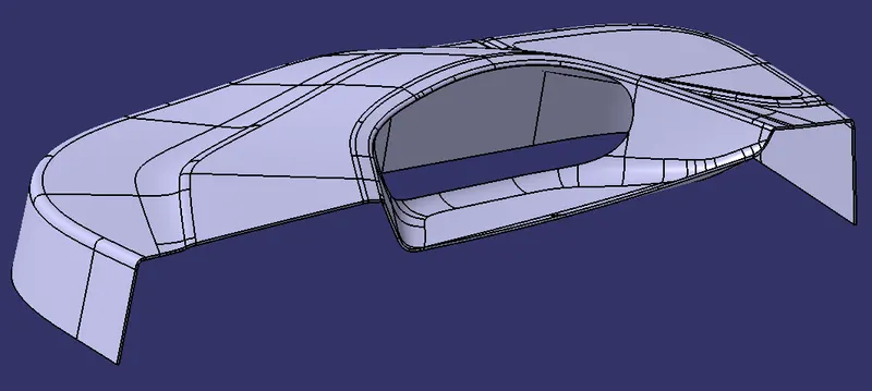
Design of engineering features on the class B surface Heat Stakes and the locator design considering the design rules.
Heat Stakes:
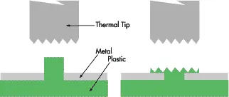
Heat staking also known as thermoplastic staking is the process of joining two dissimilar materials together. In heat staking, we use local heating and cooling to raise the temperature of plastic components and allow plastic reforming to be carried out.
DRAFT ANALYSIS OF THE FINAL COMPONENT
Draft analysis is an operation that is performed to know the draft angles of the surfaces concerning the tooling direction.
The minimum feasible draft angle for this design is 3 degrees. Generally for plastic components, a minimum draft angle that can be achieved is 0.5 degrees
- Go to the Insert menu and select the Analysis option.
- Select Feature Draft Analysis.
- Select the Material option and select the surface.
- Drag the compass and place it on the tooling axis.
- click on the surface and see that the surface is within the permissible limit of the draft values.
- Click on Okay.
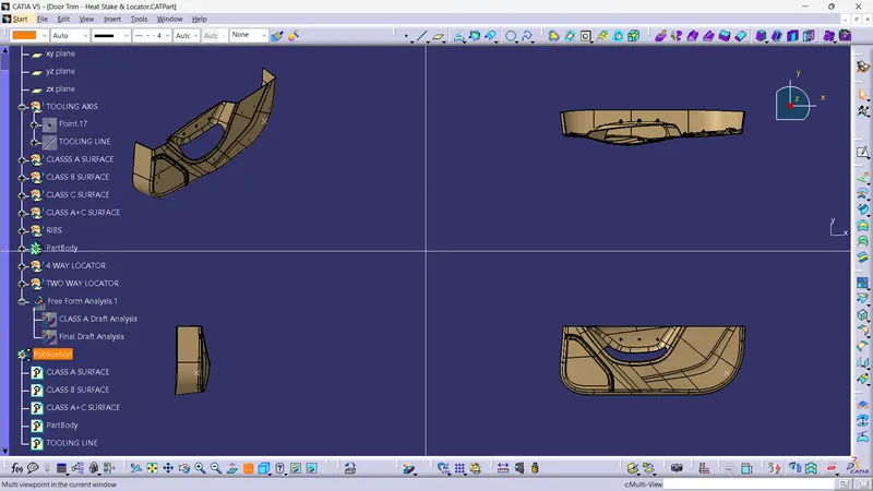
VIEWS:
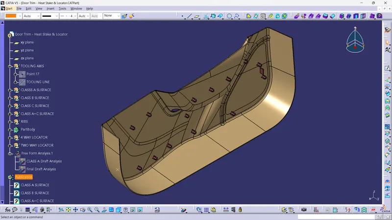
ISOMETRIC VIEW:
FRONT VIEW:
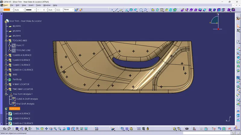
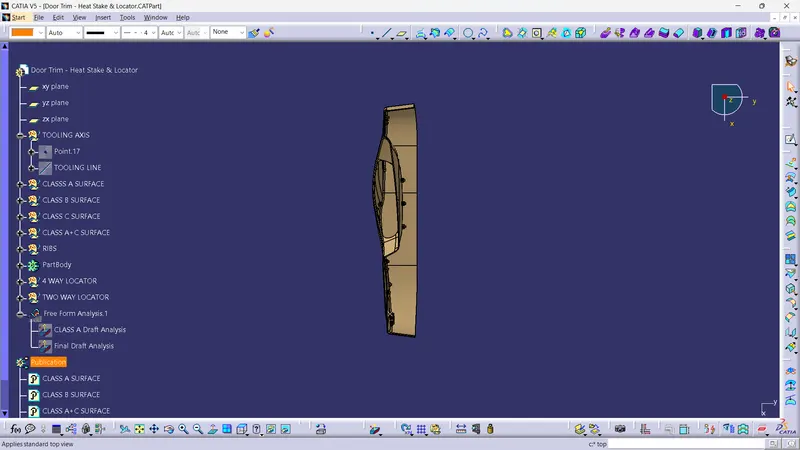
TOP VIEW:
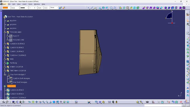
SIDE VIEW:
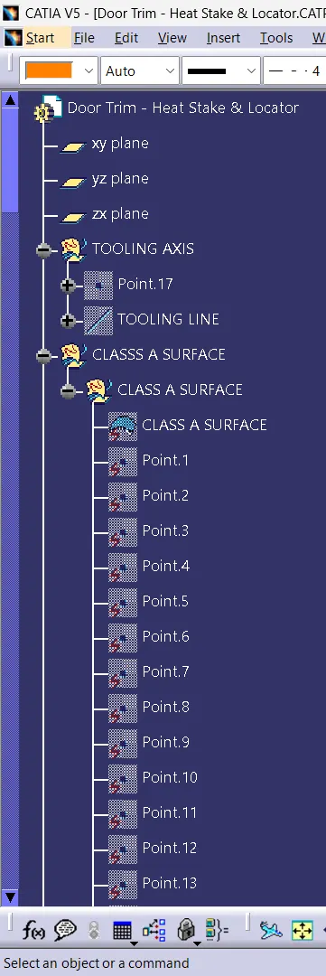
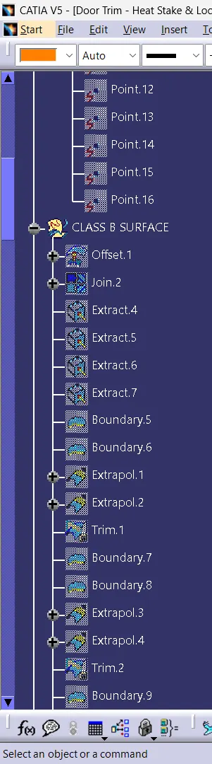
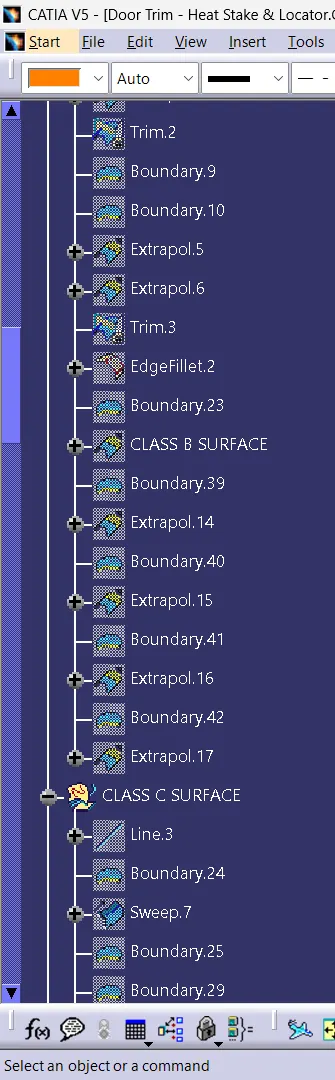
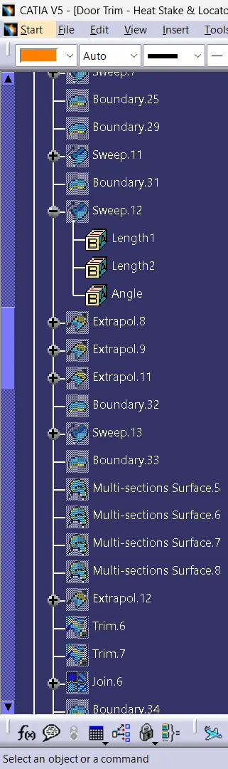
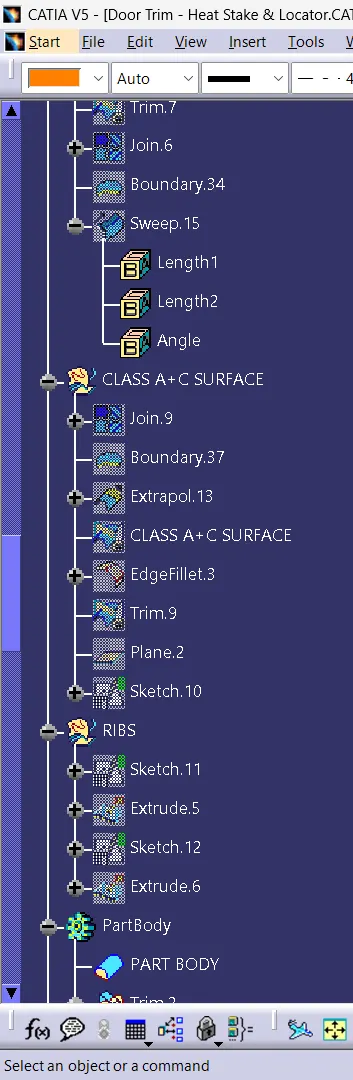
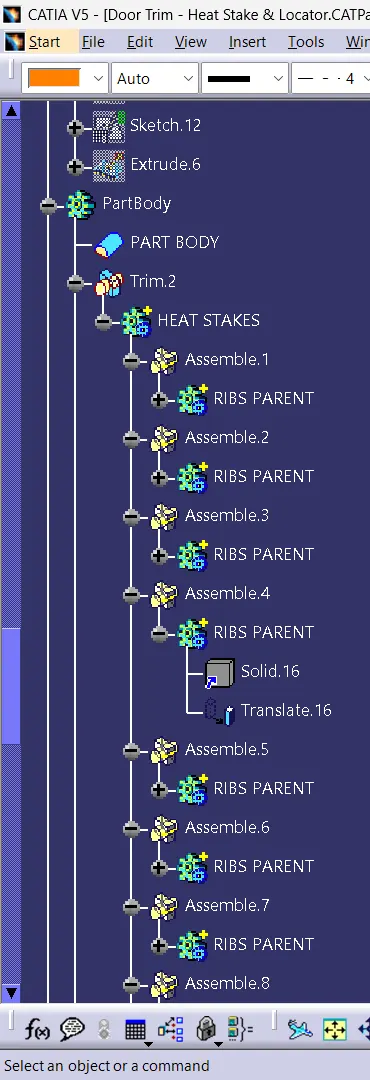
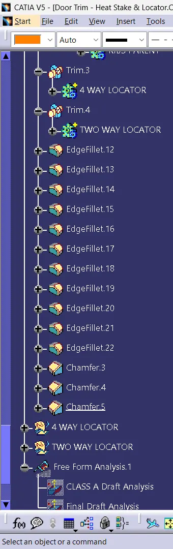
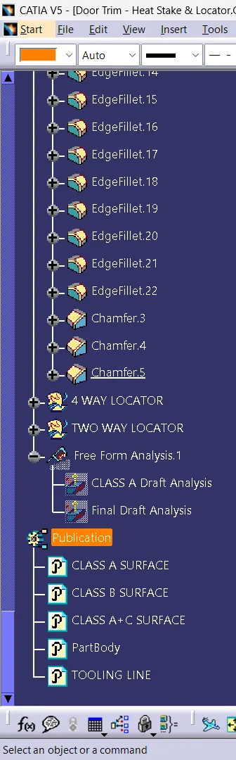
TREE STECTURE: