Week 9 - Challenge 1 - Base Bracket Design
AIM :
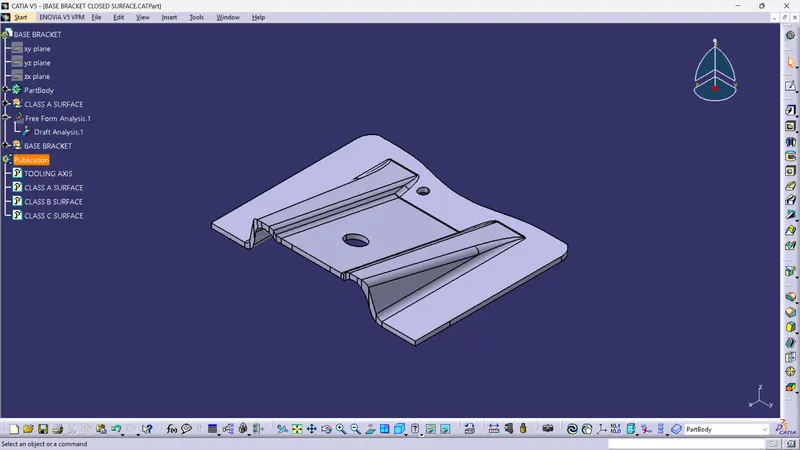
To create the Base Bracket Plastic component through the given Class-A surface.
OBJECTIVE :
- To make sure that the model meets the requirements of the draft angle.
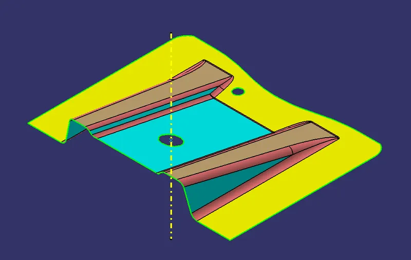
- To create the Tooling axis using bisecting method.
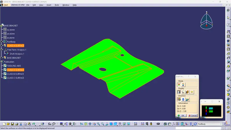
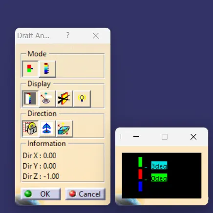
- To perform Draft analysis on the given Class A Surface.
- To create the required Class B and Class C surfaces.
- To obtain a solid body from the surface using Close Surface feature.
Draft Analysis:
- Draft analysis helps to detect if your drafted part is easily removable from the mold (in case of plastic component) or die (in case of sheet metal).
- All plastic components will have a minimum draft of 0.5 to 3deg.
- And for automotive sheet metal parts the draft will be 7deg or more.
- If a mold wall is perpendicular to the part ejection, there is ample friction or interference between the mold and the part which will not allow one to release from the other.
- This is why design engineers give a minimum draft to the part.
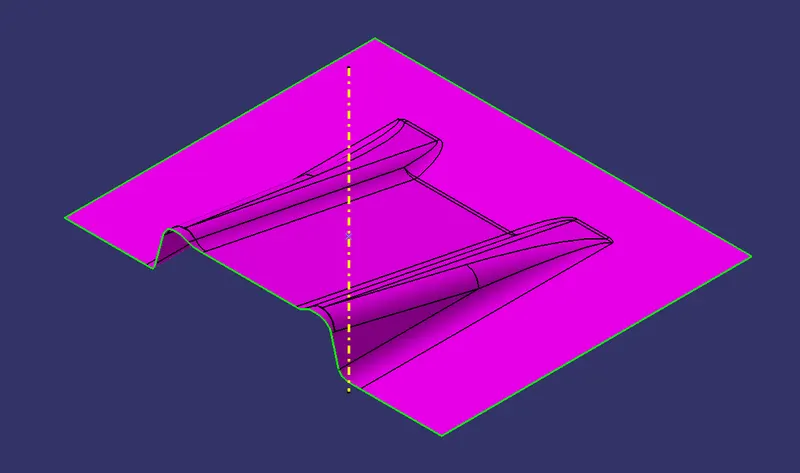
CLASS A SURFACE :
- Class A surfaces are those surfaces which are curvature continuous while providing the simplest mathematical representation needed for the desired shape and does not have any undesirable waviness.
- The Class A surface is the used to begin the design of a product.
- All the further intricacies of the component are created based on the Class A surface.
CLASS B SURFACE :
- The Class B surface is created from the Class A surface , keeping the thickness of the component in check.
- The Class B surface resembles an offsetted surface from the Class A.
CLASS C SURFACE :
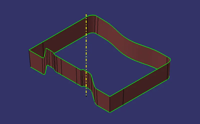
- The Class C surface is used to bind the Class A and Class B surface together inorder to form a closed surface.
PROCEDURE :
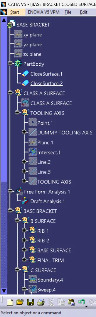
Creating Tooling Axis
- Initially the given Class-A surface was imported and checked for any discrepencies in the boundary.
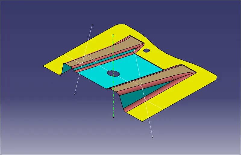
- A dummy Tooling axis was created using a reference point created on a hole of the given surface.
- The lines which might cause trouble during the operation were identified and a reference line was created for each of the identified lines.
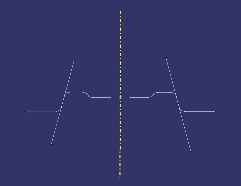
- Finally a Tooling axis was created from these two reference lines using Bisecting option.
Creating Class B Surface
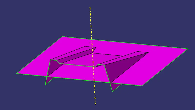
- Initially the ribs were created from the Class A surface.
- The required surfaces were obtained from the Class A surface using Extract command.
- These surfaces were further expanded using Untrim and Extrapolate commands.
- The protuding surfaces were trimmed using the Trim command and a proper continuous surface was obtained.
- The same procedure was followed for the other side aswell.
- These surfaces were offsetted according to the required thickness of the component.
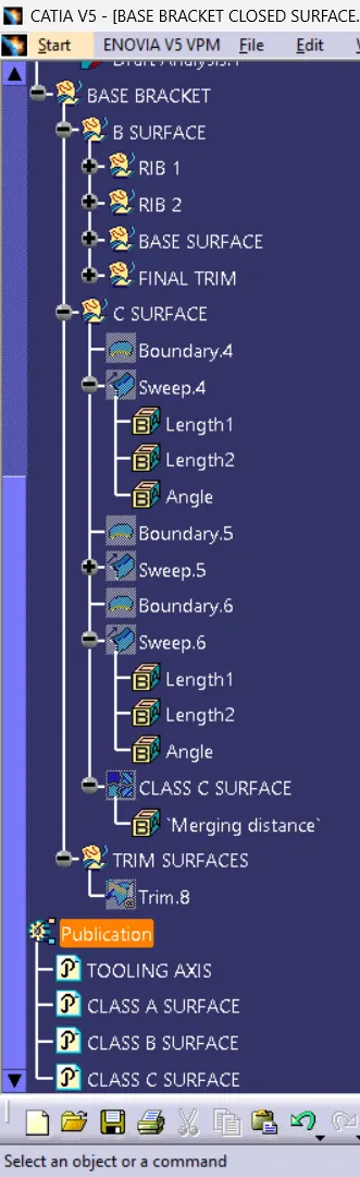
Creating Class C Surface
- The Class C surface connects the Class A and Class B surface.
- Initially the outline of the Class A surface was obtained using the Boundary command.
- The the Sweep command was used along With draft direction, with a draft angle of 3 degree.
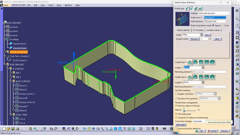
- Further the holes presented in the surface were created in the same manner.
- All the swept surfaces were finally attached to the Class A surface using the Join command.
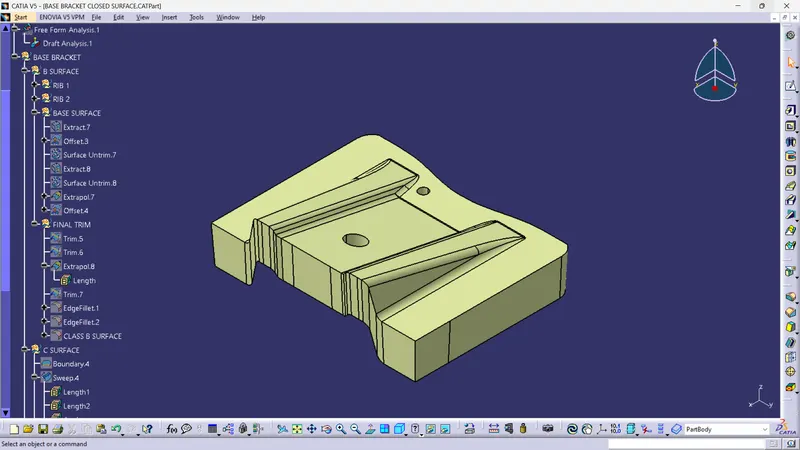
- Finally all the 3 surfaces were trimmed to form a closed surface.
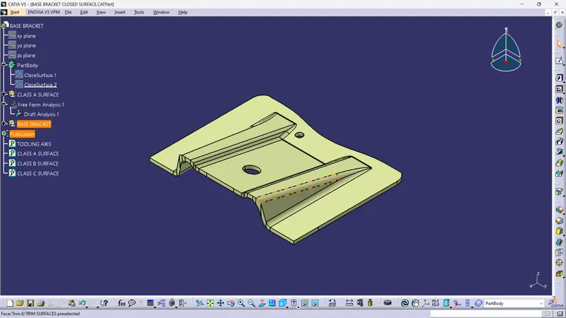
Creating Solid Body
- Using the surface created the solid component was obtained using the Close surface feature present in the part workbench.
- The Tooling axis, Class A, B and C surfaces were published.
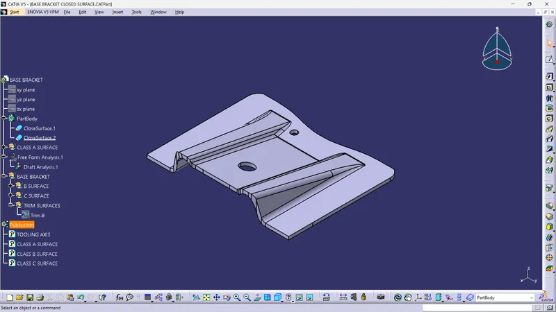
Feature tree
Views
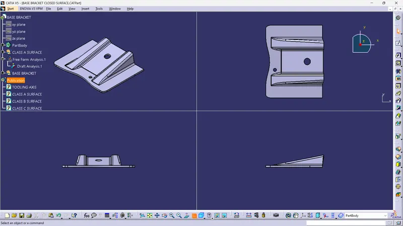
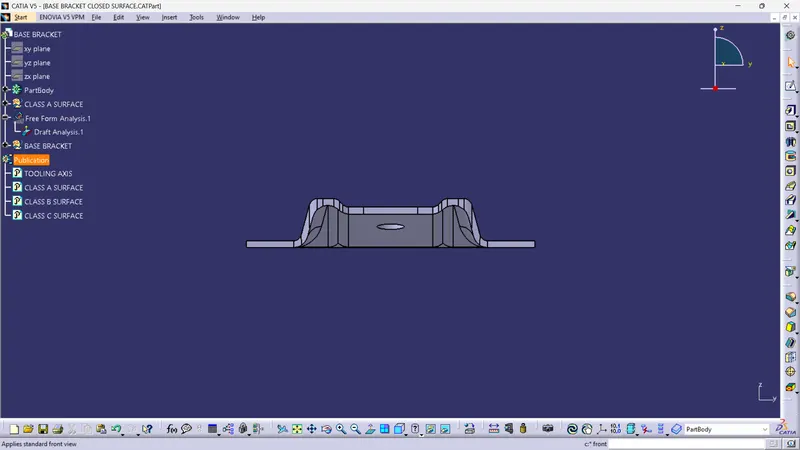
Front view
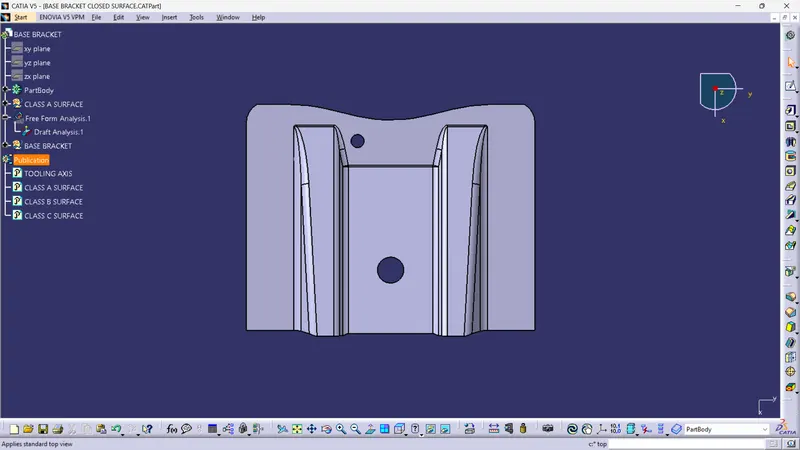
Top view
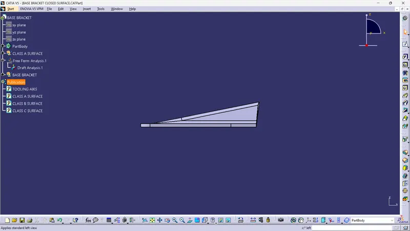
Side view
Isometric view