Week 9 - Challenge 2 - Switch Bezel Design
SWITCH BEZEL DESIGN
Aim:
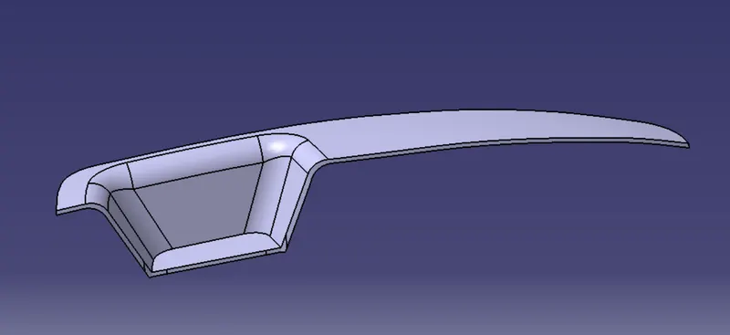
To create the Switch Bezel Plastic component through the given Class-A surface.
Objectives:
- To design switch bezel from given Class A surface
- Create a tooling axis,Class B and Class C.
- Converting closed surface into solid and perform draft analysis on the final component.
Software used:
Catia V5
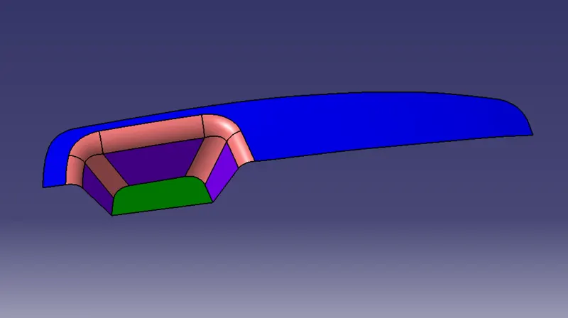
Given Class A
Creation Of Tooling Axis
To continue the designing process we need create the tooling axis first for the surface.
The tooling direction is created by bisecting method.
- The base surface of the class-A was extracted and a point is made at the center and an axis system is inserted.
- Then using project intersection along yz plane is created and the two inclined lines were drawn inside the positioned sketch.
- Then the bisecting lines with the two inclined lines were drawn.
Now the same is done along the xz plane but on one side we don't have inclined lines so the center point is used to extrude a line along the z-direction.
With the two lines from sketches 1 and 2,the bisecting line is created and published as tooling axis.
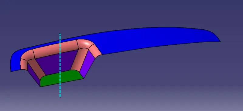
Here the blue dotted line is tooling axis.
Creation of Class B
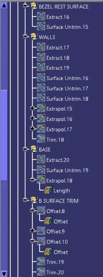
For creating the class-B surface the required surface except the offset surface have been extraced and then untrimmed all the surface.
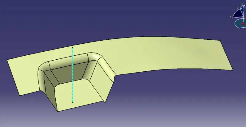
Then all the surface have been extrapolated to get intersections between them
Creation Of Class C
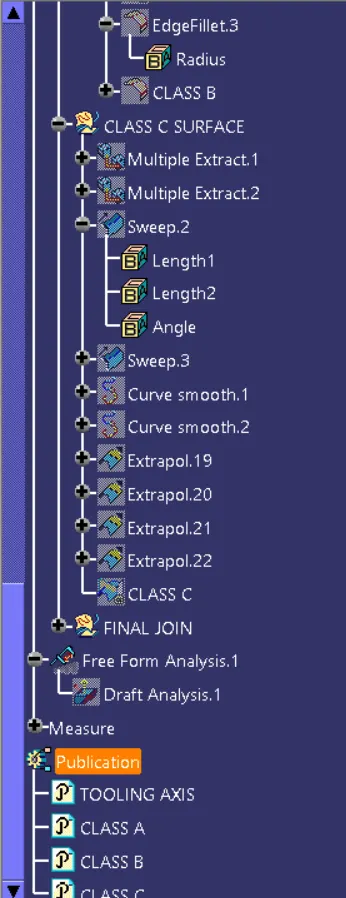
The required outer edges of the A-surface were extracted using Multiple Extract.Then for avoiding the patches the curve is smoothened using the curve smooth option.Then by using the sweep command the surface was created.
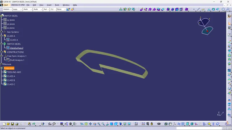
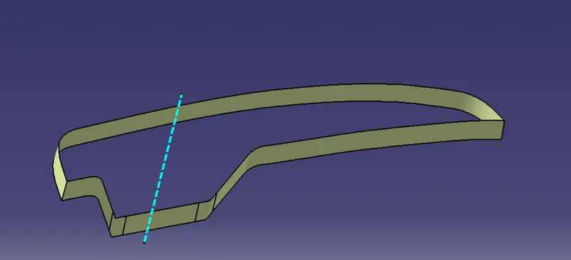
Class A+Class C
By Using Join Command the class A and Class B surface are joined to create a single body
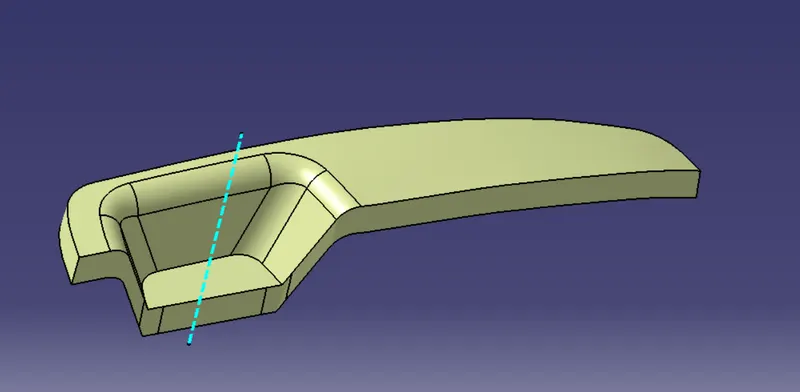
Class A+Class B+Class C
By Trimming the joined Class A & C surface with class B the Class A+Class B+Class C is created.
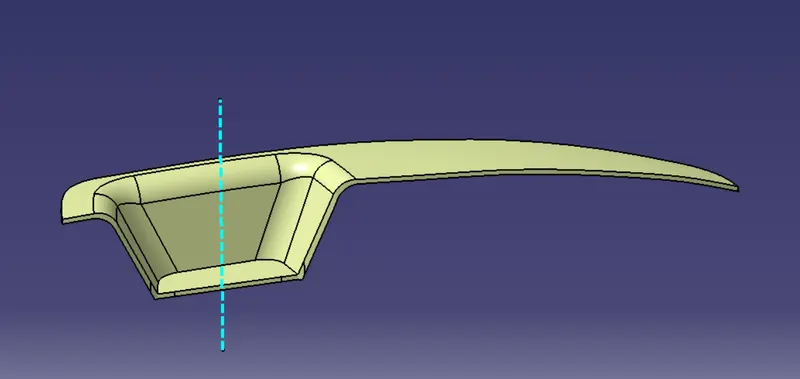
Final Solid
Using Closed surface command in part design the final solid is created.
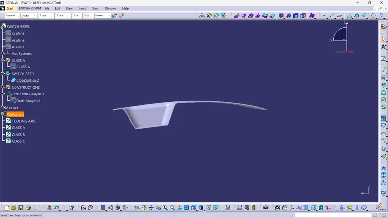
Views:
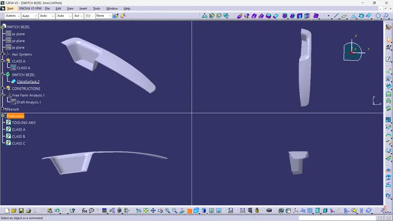
Front view
Side view
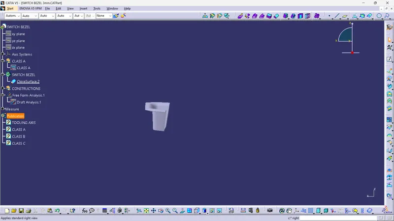
Top view
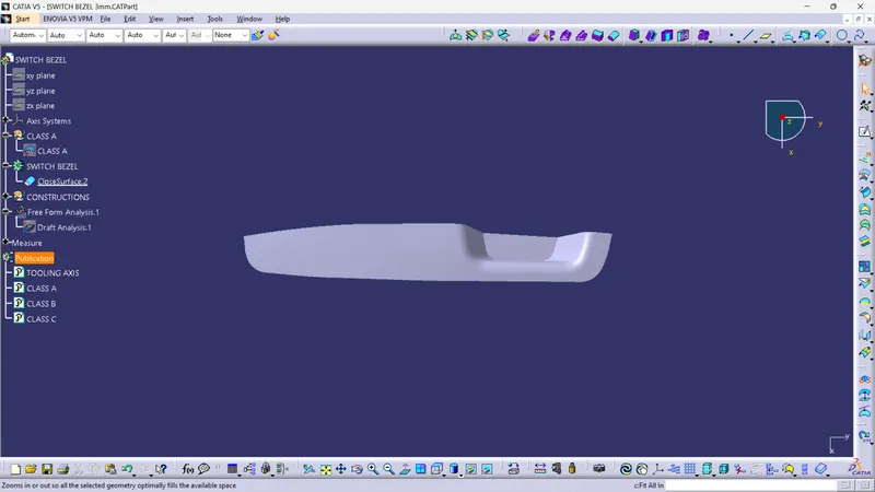
Isometric View
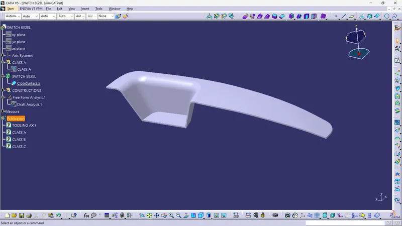
Overall Views
Draft Analysis
When the design is complete, draft analysis is done on the component.
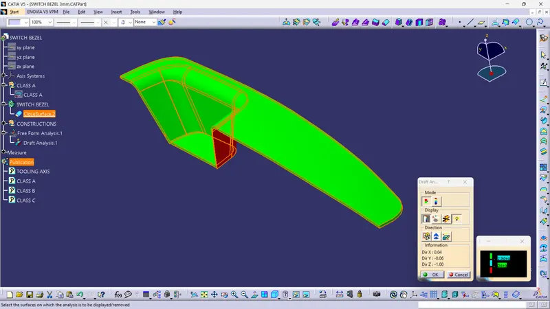
After draft analysis is done we can observe that the green colour shows that the drafted walls of the switch bezel are above 2.9 degrees which is a permissible cirteria to manufacture in injection moulding.
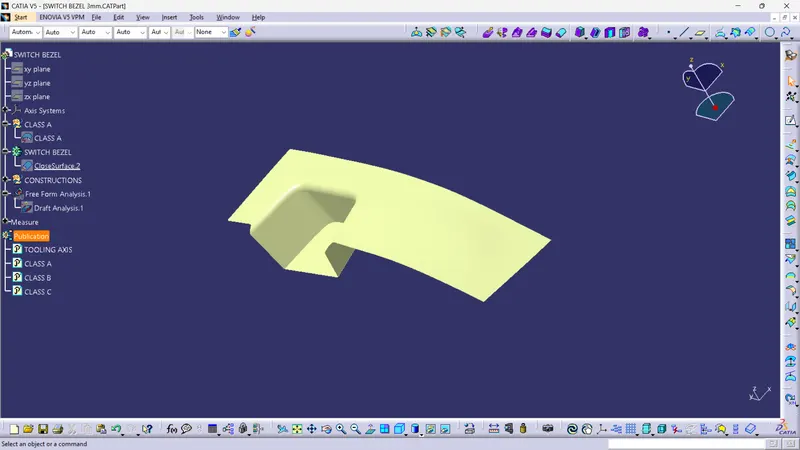
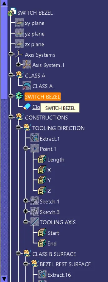
Detailed tree structure for the creation of switch bezel is represented below:
Conclusion
1. Class A, Class B and Class C surfaces are created following standards of automotive industry using Catia V5 software.
2. Draft analysis was performed on the switch bezel and it was observed that draft was under permissible limit for the manufacturing of the component using injection moulding process.