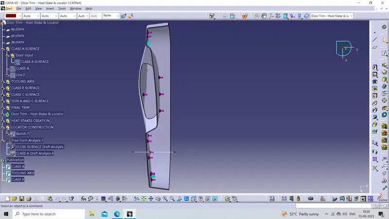
Week 10 - Challenge 3 - Door Trim Lower with Engineering Features
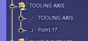
Tooling Axis
The tooling Axis is the direction in which the mold or core and cavity open and close. While designing a component first thing is to define the tooling axis.
Defining the TOOLING AXIS
To create the tooling axis first, we have to check the best suitable direction for tooling by using the compass. the y direction is suitable for creating the tolling axis because, in the y direction, most of the surfaces are clearing while performing draft analysis. Generally tooling axis is created using bisecting line method but here A line normal to the surface is created in the y direction and considered the tooling axis.
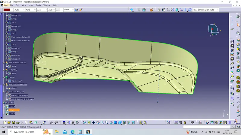
Tree Structure
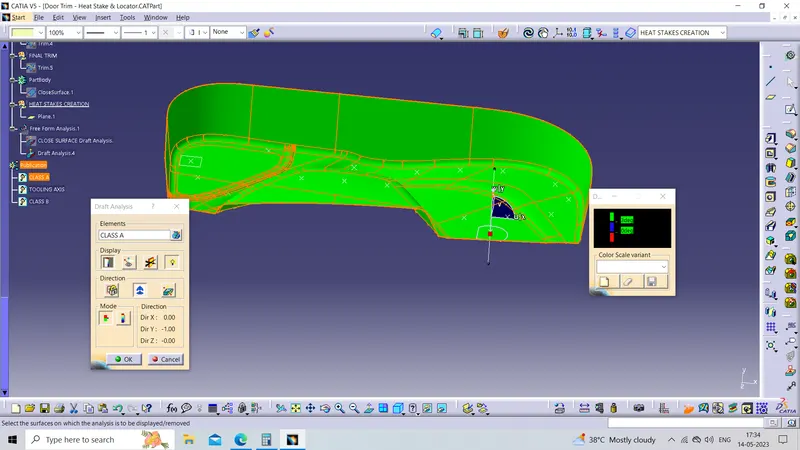
Draft Analysis on CLASS A SURFACE
Draft analysis is used to analyze whether the part model created in CAD is manufacturable based on the draft condition applied.
The draft is required on all parts in the direction of mold movement to allow parts to release or eject from the mold properly. Most parts or applications require a minimum 0.5°-1° draft angle,3°is widely accepted as the norm.
Procedure
1. First change the view to " Customize View Parameters" and select the Material option.
2. Select Feature Draft Analysis from the toolbar.
3. Click on the direction, drag and drop the compass to the component such that it should coincide with the tooling axis.
4. Lock the draft direction and click on the component.
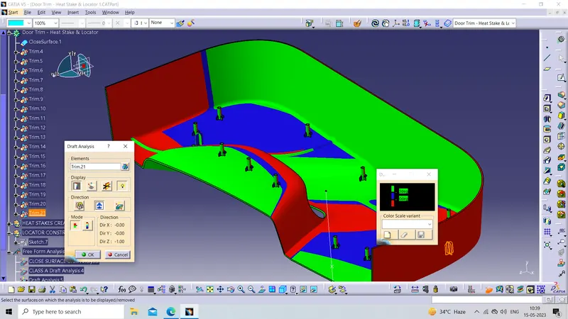
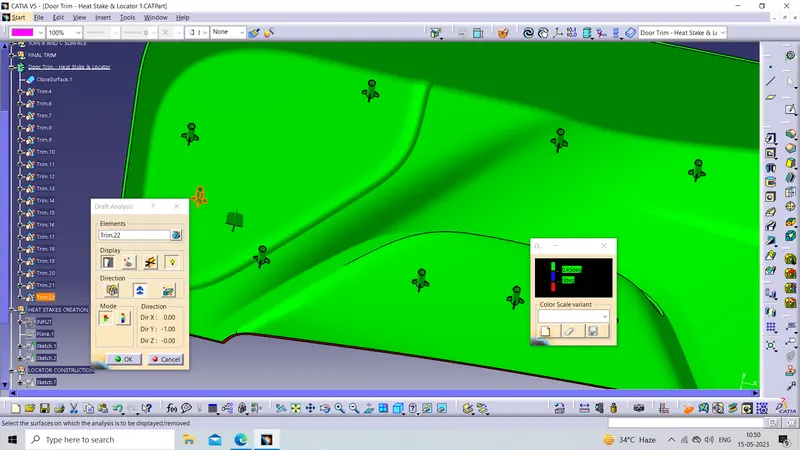
5. Green color shows the positive draft, cyan as zero degrees, and red as the negative draft
Heat Staking
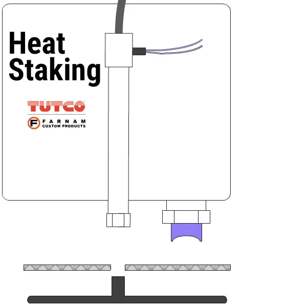
In manufacturing products with thermoplastic components, it is often necessary to join a thermoplastic to a part of dissimilar material, whether it be metal, dissimilar plastic, or other material. This technical information sheet provides design guidelines, configurations, and techniques for successful heat staking.
Thermal Staking or Heat staking is an assembly method that uses the controlled melting and reforming of plastic stud or boss to capture or lock another plastic or metal component of an assembly in place. The plastic stud protrudes through a hole in the component to be locked in place. The heated thermal tip contacts the top of the stud, which melts and fills the volume of the tip cavity to produce a head, locking the component in place. The progressive melting of plastic under continuous pressure forms the head. The right combination of heat and pressure for the application is critical when staking.
Heat staking also known as thermoplastic staking is the process of joining two dissimilar materials together. In heat staking, we use local heating and cooling to raise the temperature of plastic components and allow plastic reforming to be carried out. This reform can be used in a wide variety of applications.
Applications range from staking plastic bosses for the assembly of car door panels to joining PCBs to plastic housings.
Advantages
1. Simplification of machinery
2. Reduced cost of machinery
3. No vibration damage
4. No particulates
5. The ability to stake metalized coated applications
6. The capability to stake in difficult-to-access or restricted areas.
7. Multiple fastening points
8. Allow higher density of welds compared to hot air cold form or ultrasonic welding.
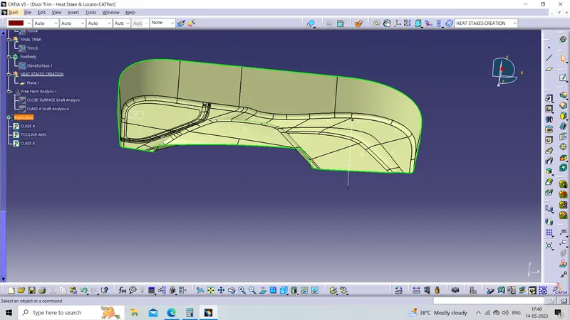
Class A Surface: Class A surface is any of a set of freeform surfaces of high efficiency and quality. In other words, the Class A surface is the aesthetic surface.
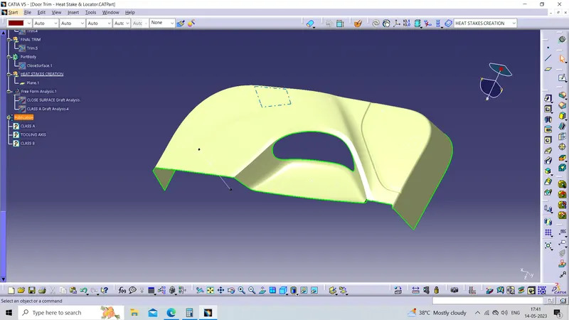
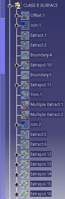
Class B Surface: Class B surface is the thickened surface or engineering surface where all ribs, screw bosses, dog houses, etc will come.
Tree Structure
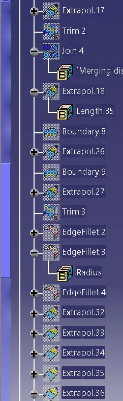
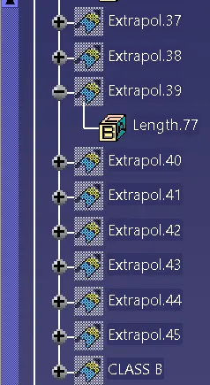
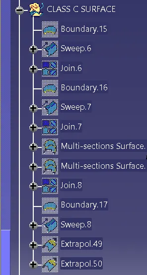
Class C Surface: It is the Surface that joins Class A and Class B surfaces.
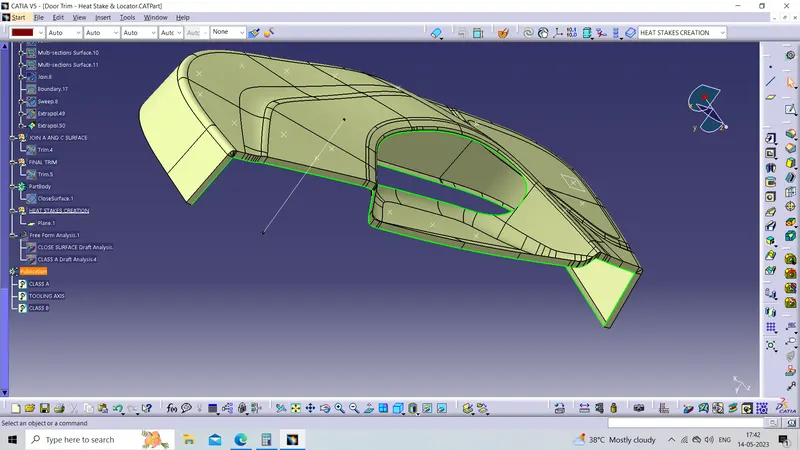
Tree Structure
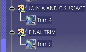
FINAL TRIM
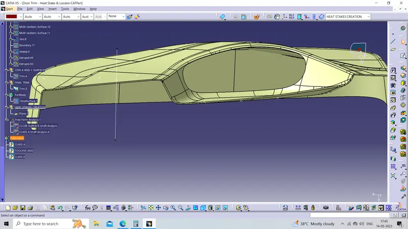
Tree Structure
Creating a solid body by using a closed surface :
To create a solid body firstly switch to the part body workbench and use the close surface command to solidify the surface body
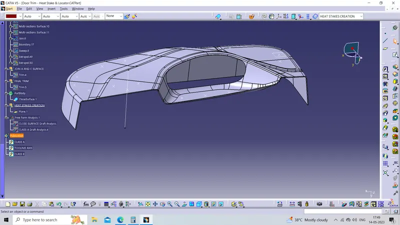
Tree Structure

Now creating the Heat Stakes
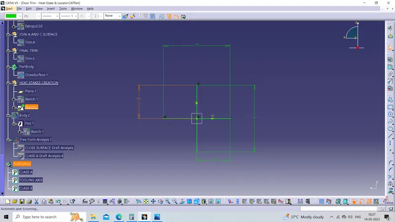
Sketch of Heat Stakes
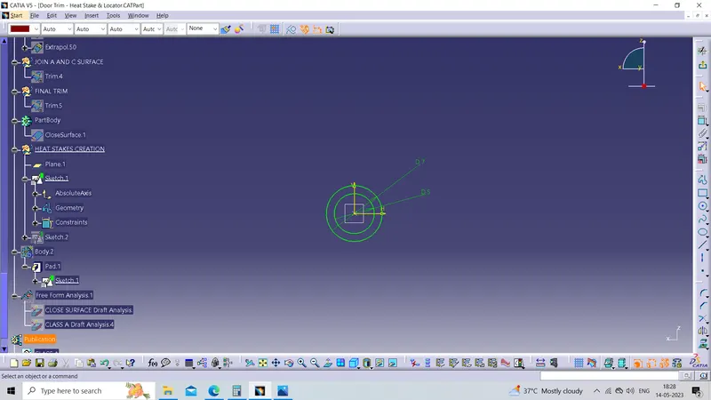
Sketch of supporting Ribs of Heat Stakes
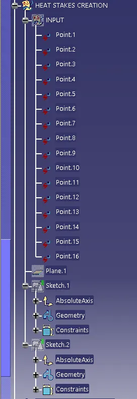
Tree Structure
now pad the above sketch as per the standard designing parameters
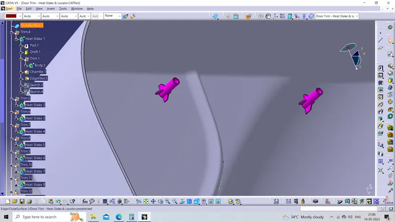
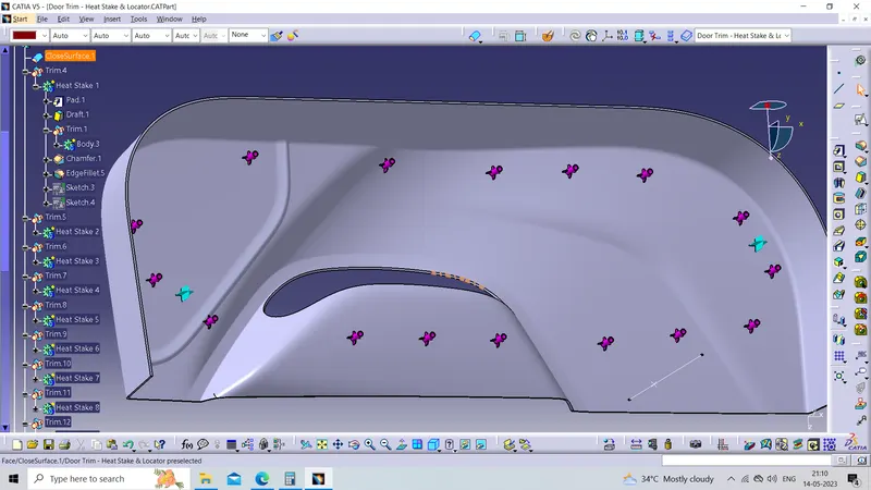
Then copy and paste special And then use the translate command to place the Heat Stakes at the desired location to minimize our efforts And then untrim them from the Main plastic body
Tree Structure
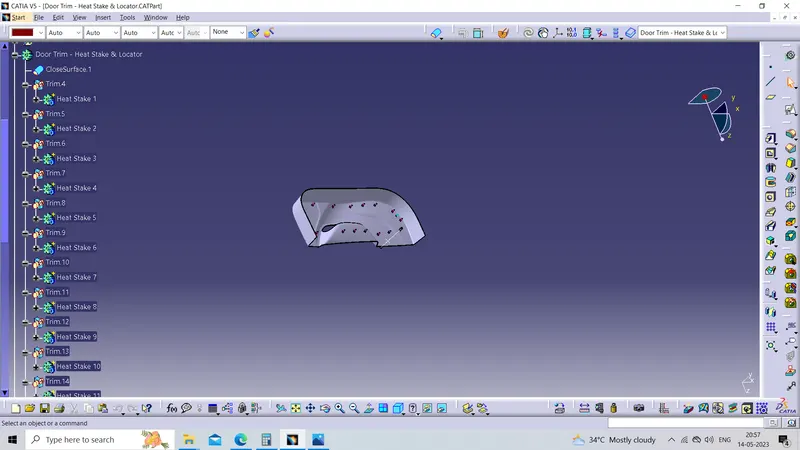
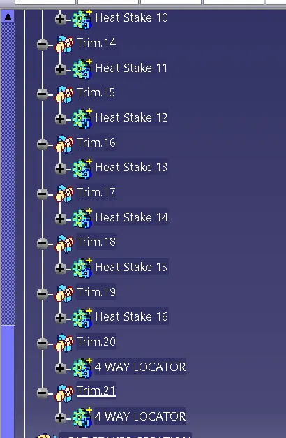
Now creating the Locator
Sketch of Locator
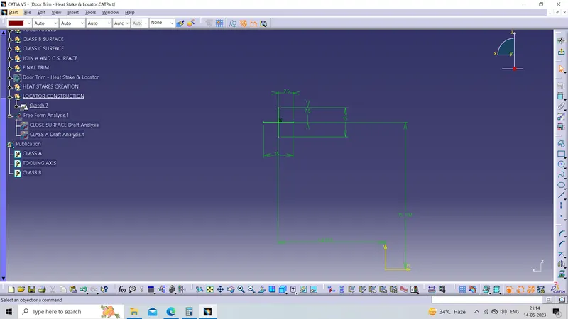
Tree Structure
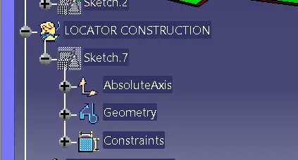
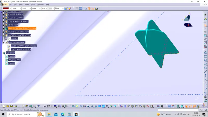
Tree Structure
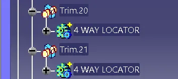
Then copy and paste special And then use the translate command to place the Heat Stakes at the desired location to minimize our efforts And then untrim them from the Main plastic body
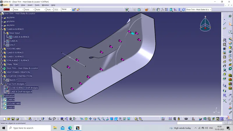
Hence our final component
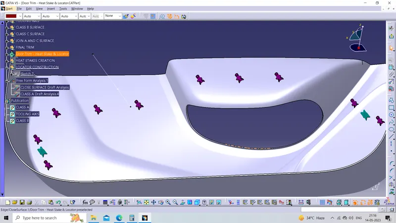
draft analysis on the final component
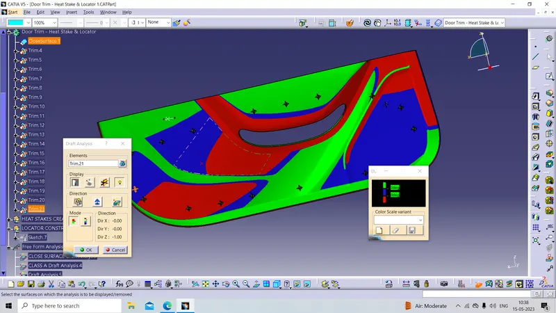
Isometric view
Front view
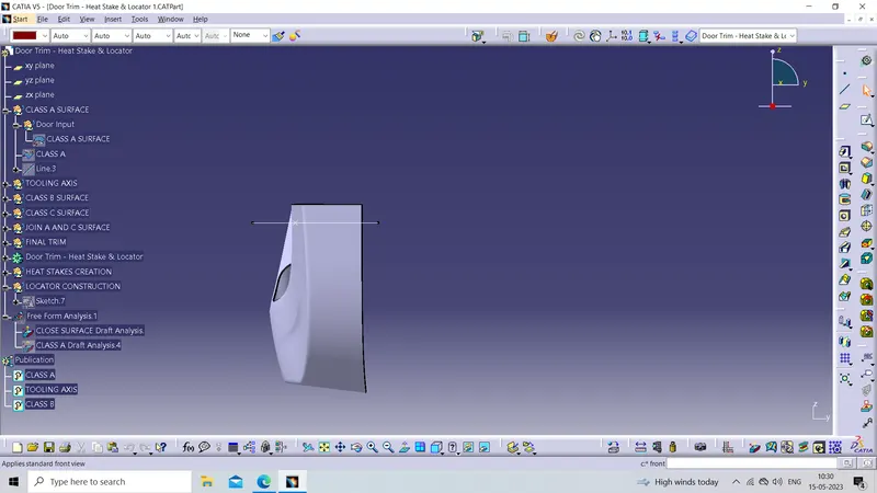
Side view
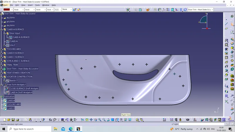
Top view