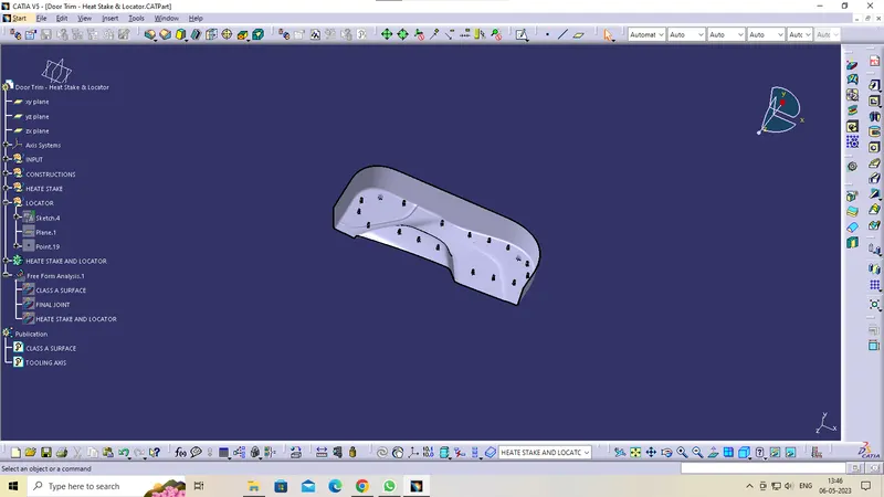
Week 10 - Challenge 3 - Door Trim Lower with Engineering Features
DESIGN METHODOLOGY
Class-A surface means visible surface. It gives the aesthetic of the component which is created by the styling team and gives to the part design engineer to create the part with all engineering aspects.
Given CLASS-A surface
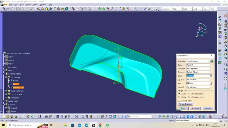
Procedure for TOOLING AXIS creation
- Check the best possible tooling direction by manually adjusting the compass.
- By analysing it is found that y axis as tooling direction would clear most of the faces without any difficulties.
- Now extract any surface and create a mid-point on it.
- Then create a dummy axis creating a line on the point and direction along the y axis.
- Perform draft analysis to find whether the given axis clearing the draft analysis. If not create a new tooling axis.
CLASS B SURFACE
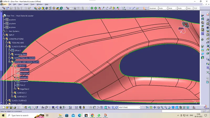
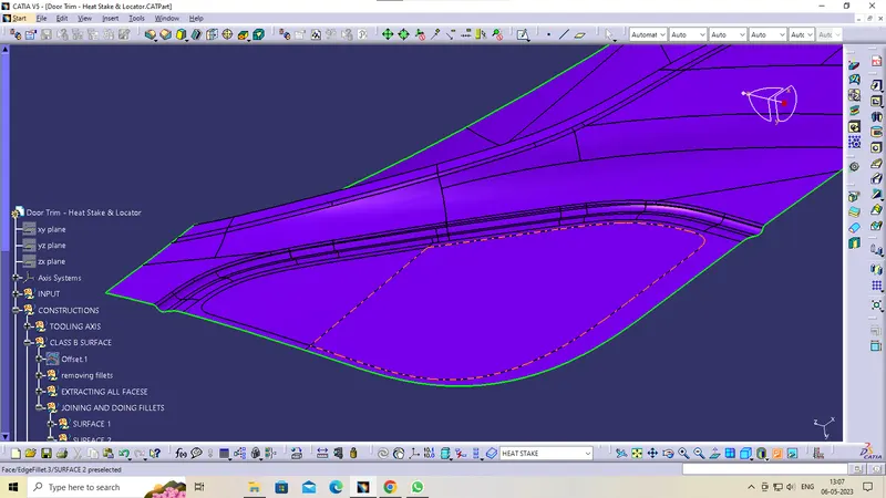
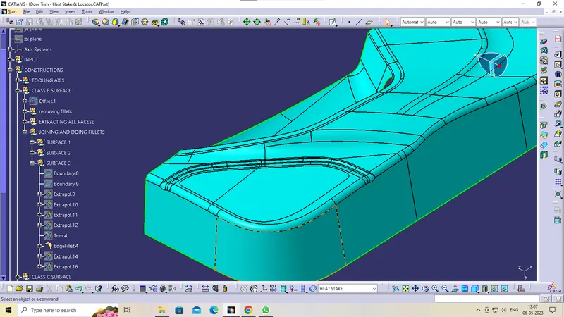
Class-B surface means thickness of a part it is not visible and is inside part. In other words, Class-B surface is a surface below a certain thickness from the class-A surface. This is the surface that contains engineering aspects of a model.
- Create offset surface of CLASS-A about 2.5mm inward direction.
- Check for the discontinuity and rework on the offset surface using extract, multi-extract, multi sections surface.
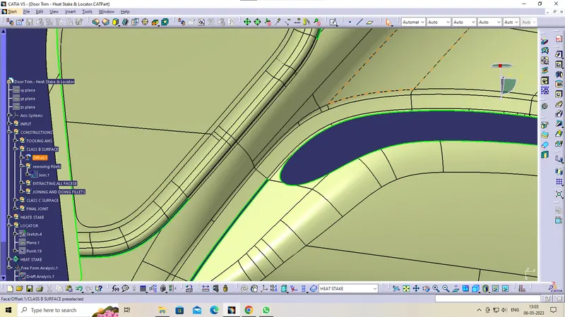
- Join the surfaces and ensure the final CLASS-B surface created has no gaps
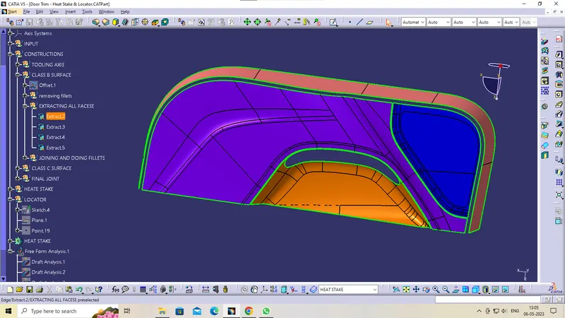
CLASS-C SURFACE CREATION
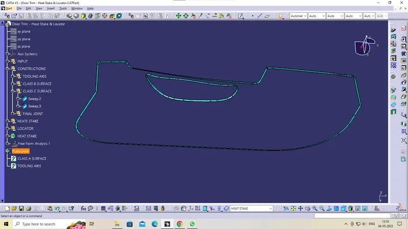
Surface that joins class-A and class-B surfaces is class-C surface. Class C is often specified for interior surfaces not readily visible, surfaces that will be covered by another part when assembled
- Create the sweep surfaces with reference to surface and tooling axis by multi extracting the CLASS-A boundary
- Join the sweep surfaces by using commands like extrapolate, trim, multi section surface.
- Finally join all the sweep surfaces and ensure the continuity of the CLASS-C surface.
CREATING THE FINAL JOINT
- For creating the Finals door trim surface, join the CLASS-A and CLASS-C surface together.
- Then Extrapolate the B surface little bit outward direction to make sure that there would not be any gap when trimming with joined surface.
- Then trim the extrapolated CLASS-B surface with Join surface (CLASS-A and CLASS-C)
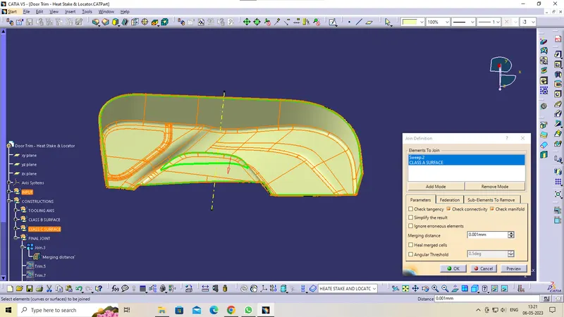
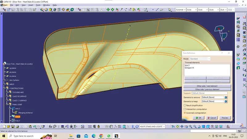
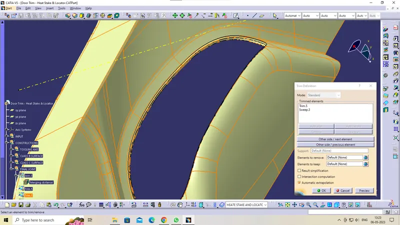
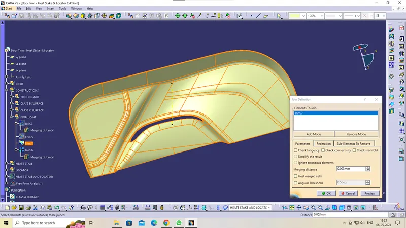
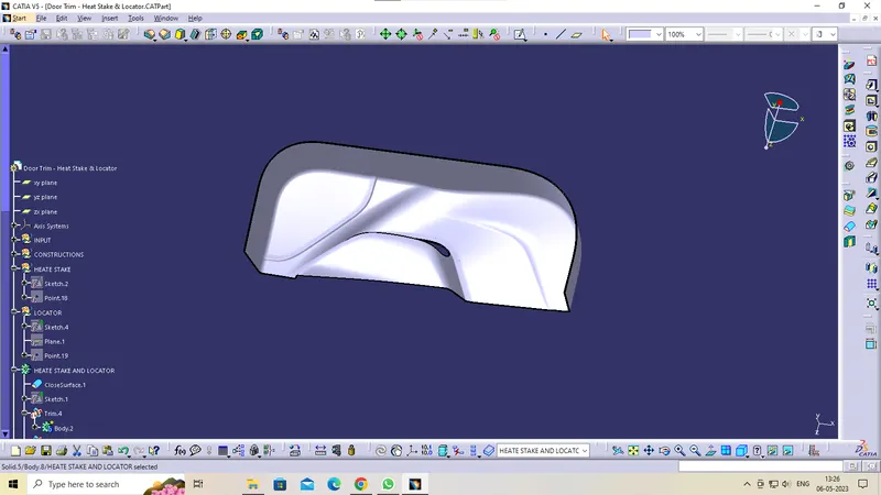
Make a solid part body using the close surface command in the part design workbench
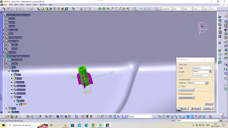
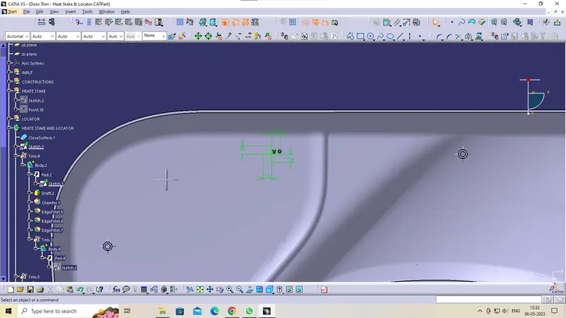
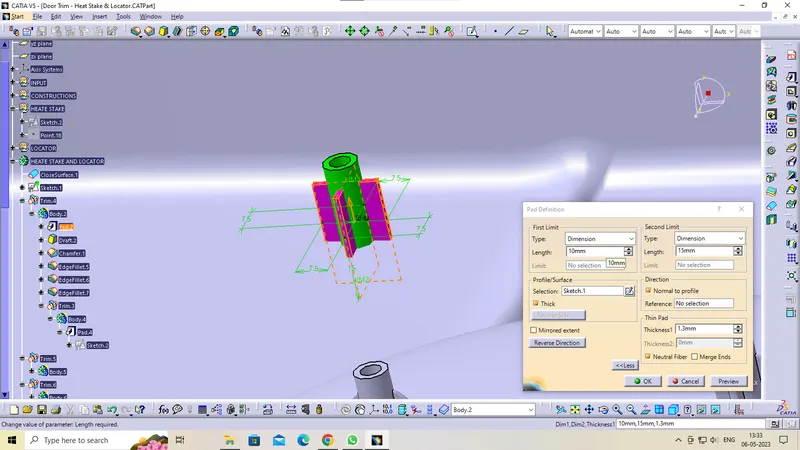
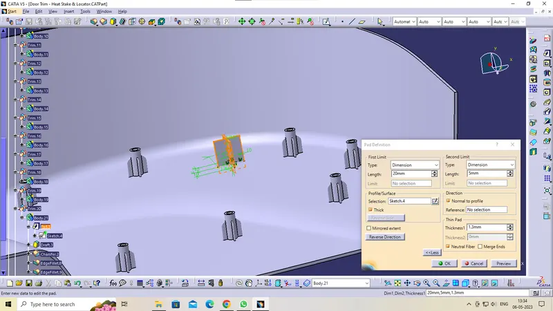
HEATE STEAKE DESIGN:
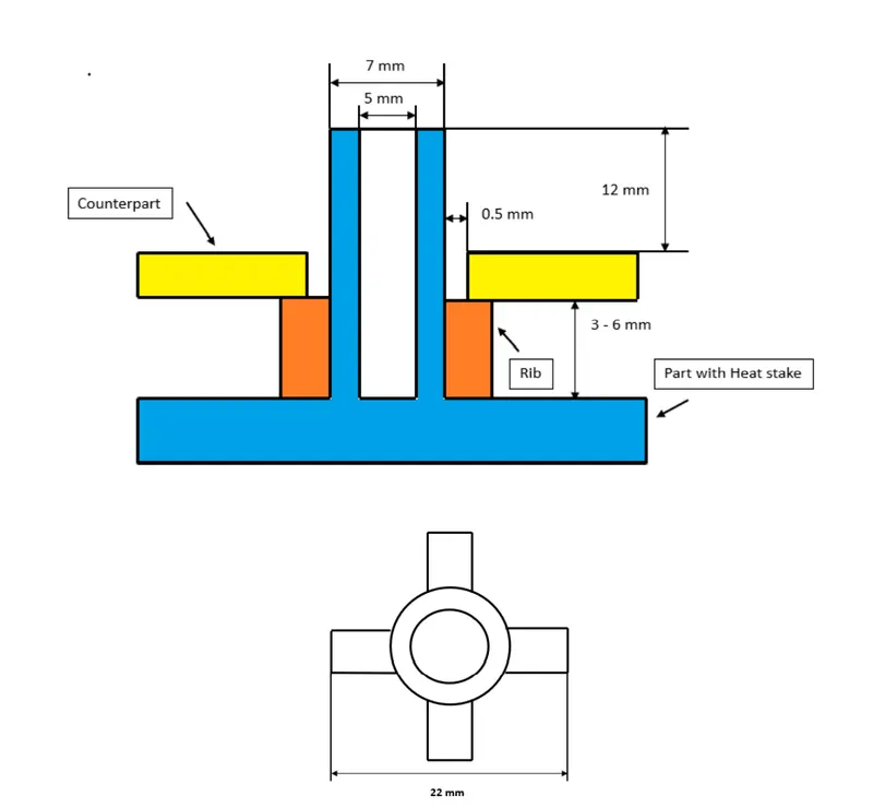
- Counter Part Thickness - Will be given as input
- Component Wall Thickness - Will be given as input
- Length of the Rib - 22 mm
- Height of the Ribs - 3 mm to 6 mm
- Inner Diameter of Heat Stake (d) - 5 mm
- Outer Diameter of Heat Stake (d) - 7 mm
- Minimum clearance between heat stake and counterpart - 0.5 mm
- Height of the Heat stake - Depends on the rib height and counter-part thickness
- Minimum fillet of Heat Stakes - 0.25 mm
- Minimum Draft Angle of Heat Stakes - 0.5 degrees
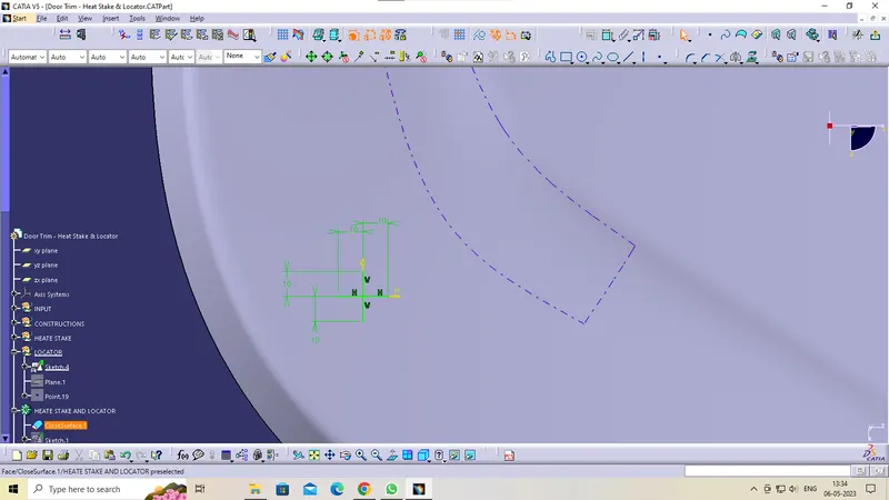
LOCATOR
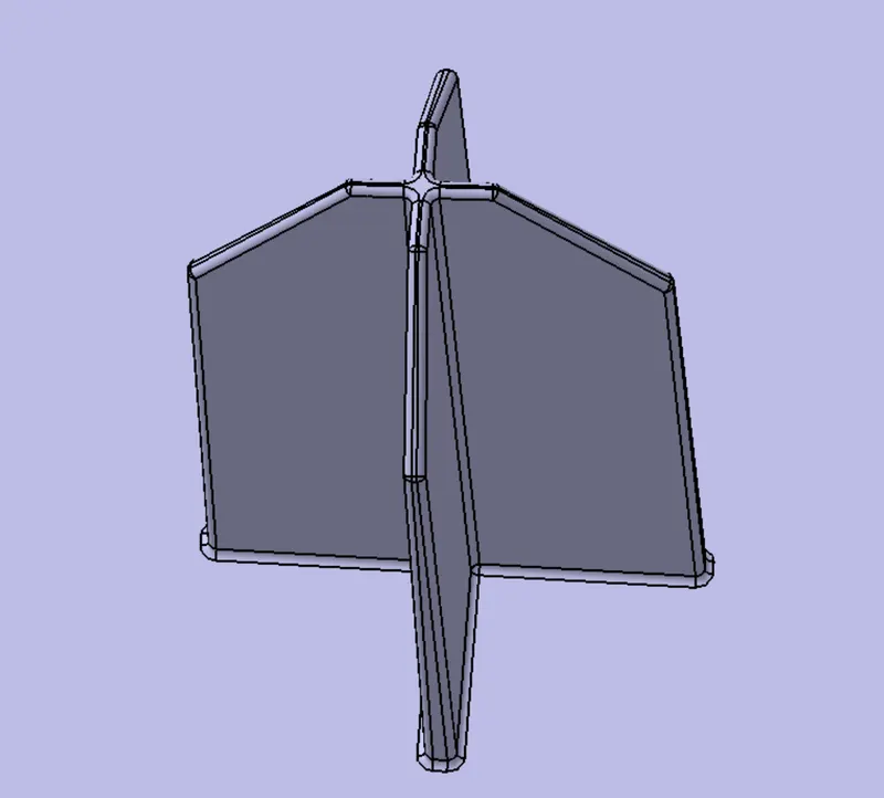
- Height of the locators should be 1 mm (or) 2 mm greater than the heat stakes
- Thickness, fillet and draft angle are of same as rib design rules.
- Ideal Chamfer value - 5 mm x 45 degrees
- Ideal length of the locators - 15 mm
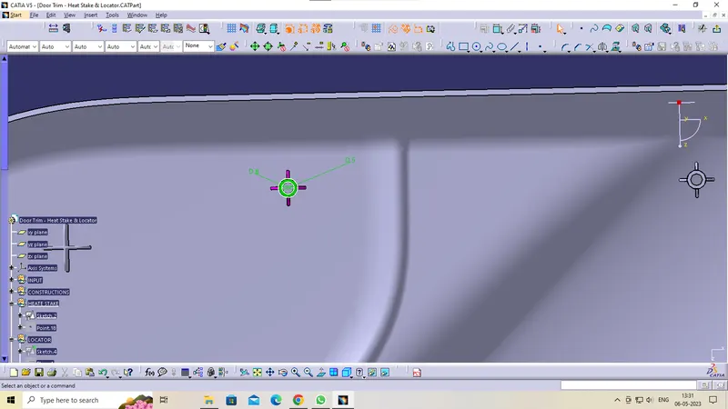
DRAFT ANALYSIS
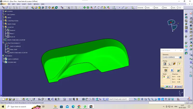
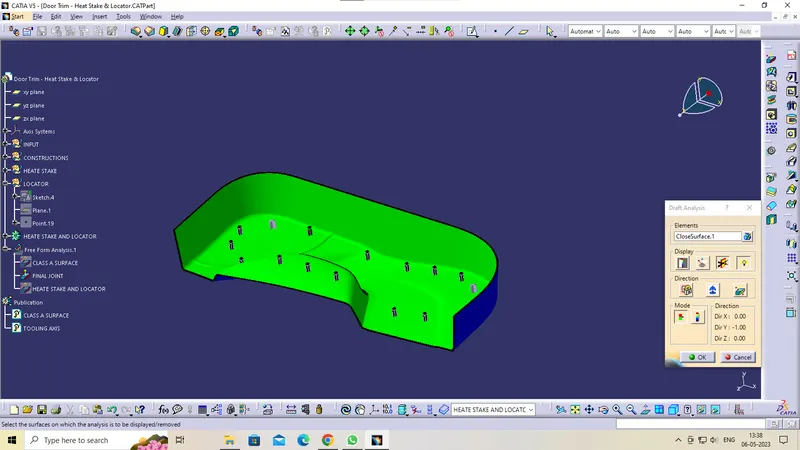
The Draft Analysis is a command enables you to detect if the part you drafted will be easily removed. This type of analysis is performed based on colour ranges identifying zones on the analysed element where the deviation from the draft direction at any point, corresponds to specified values.
Draft analysis is done after determining the tooling axis, draft analysis is used to check whether the minimum draft (3 degrees) is maintained or not.
- Procedure for performing the draft analysis are as follows
- Change the view mode of the component to be in customized parameter mode and then select the shading mode as materials.
- Then open the featured draft analysis tool from the insert menu.
- Then click on use the compass to define the current drafting direction and then drag and align the compass on the Tooling axis.
- Then lock the draft direction and perform draft analysis by clicking on the component.
Colour Range representation
GREEN colour - Positive Draft
RED colour – Zero draft
BLUE colour – Negative Draft
Draft analysis of CLASS-A surface
Draft analysis of CLASS-A ,B,Csurface
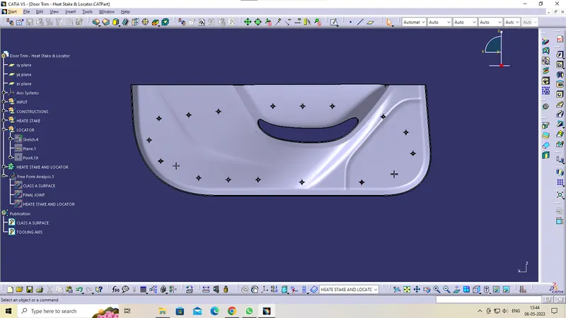
Draft analysis of heate stake and locator
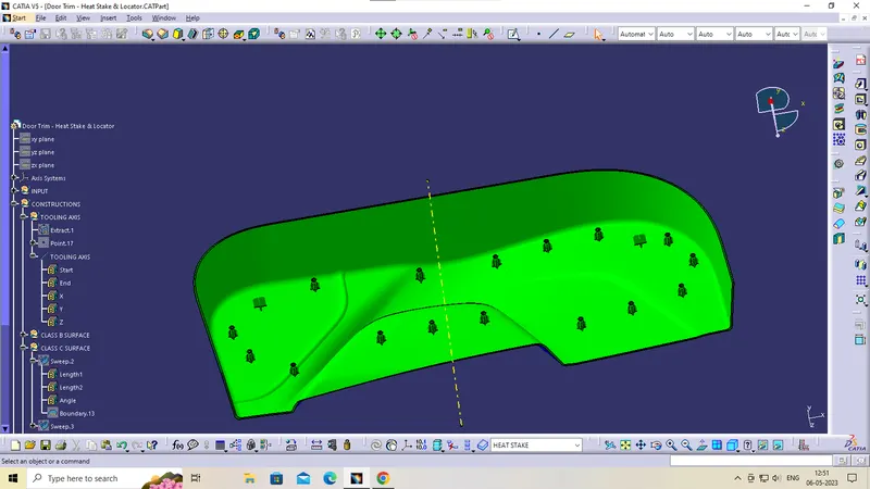
VARIOS VIEWS
FRONT VIEW
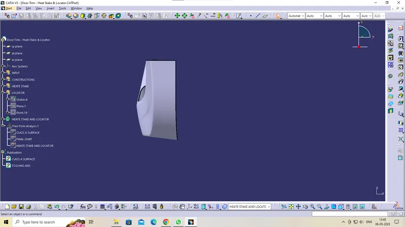
SIDE VIEW
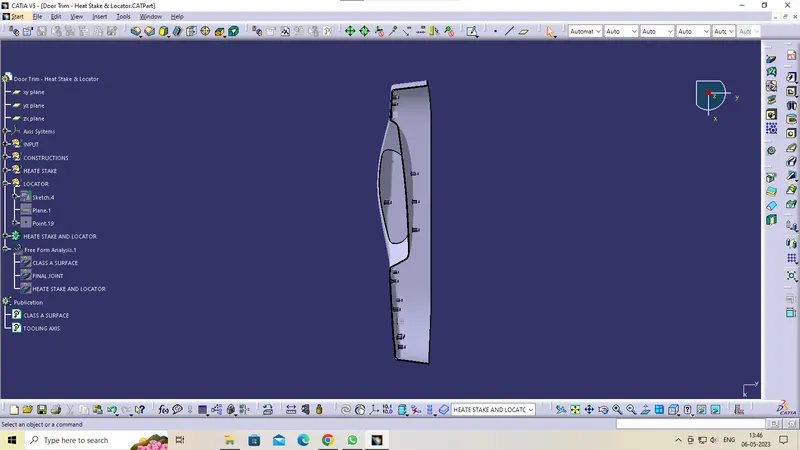
TOPVIEW
ISOMETRIC VIEW