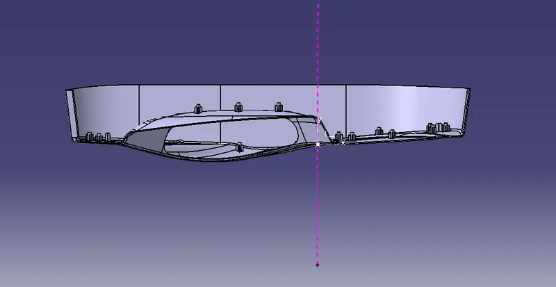
Week 10 - Challenge 3 - Door Trim Lower with Engineering Features
Report :
Here we have given A Class Surface
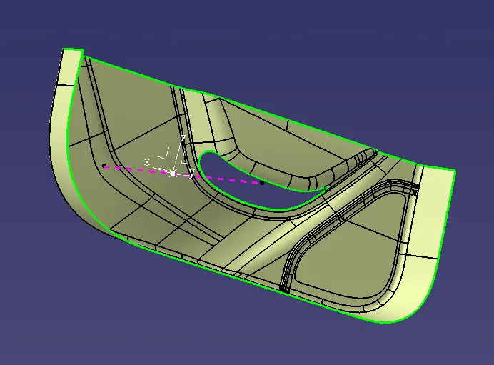
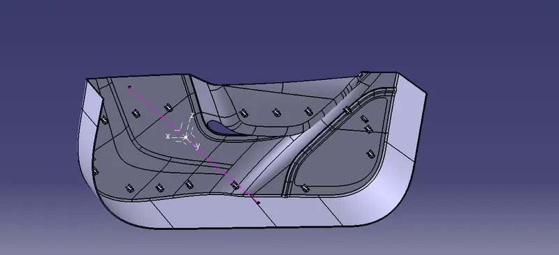
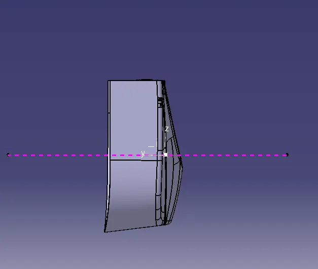
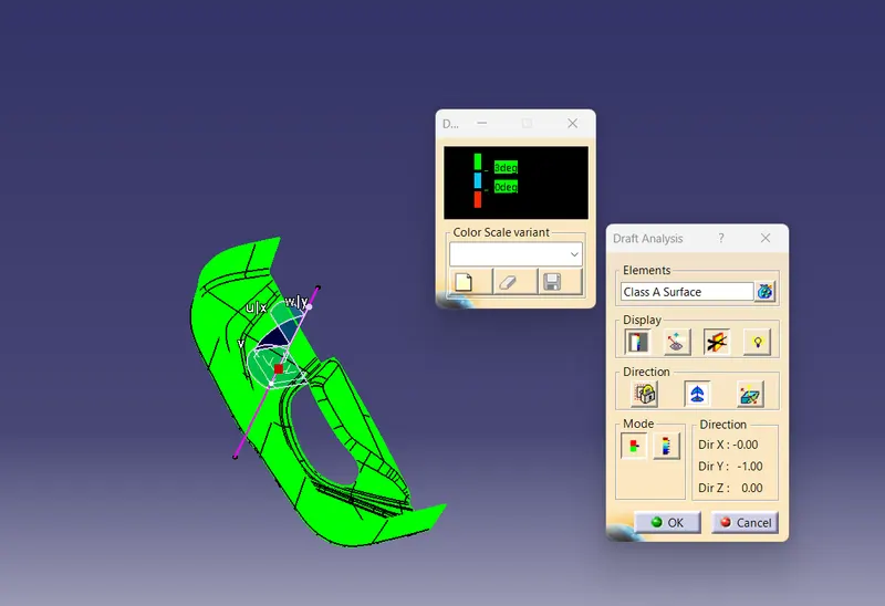
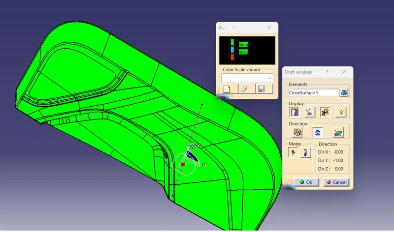
Now we have to create a Tooling Axis on the direction in which the part should be added to the mould for creating that we should have to take an axis system to the point which we think can create problem while moulding. Thus After Creating tooling axis we can make a draft analysis to get sure about the tooling axis normally draft analysis should be given to be 0.5 to 3 degree, Here I have taken 3 degrees. my draft angle is Correct according to tooling axis.
To begin, we must first move the Door Trim class A surface inward by the desired thickness (in this case, 2.5mm). Then, we must close the patches that were created on the bumper's offset surface due to the fillets on the Class A surface. Once all the patches have been closed and properly joined, we can create a Class B surface by sweeping the boundary of the Class A surface and trimming it with the Class B surface to form a closed body.
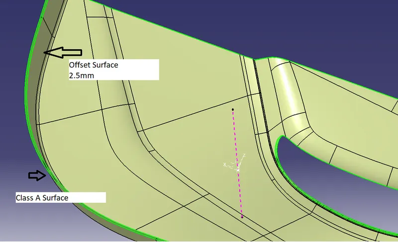
After Done with Class A and Class B, We can start creating class C Surface which can be made using sweep command with reference to surface, along 90 degree angle with the help of Class A Boundary,
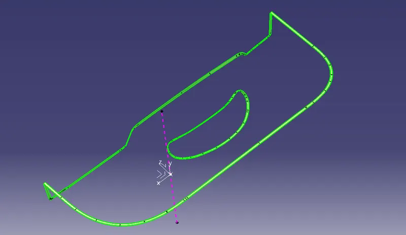
After Creating Class A+B now that we have class C surface we can now close the part body with the help of trim command and but first we should to define all the surface are getting intersected with each other if not then we should have to extrapolate the surface to some amount.
when we are done with all this commands we can now create the final plastic part woth the help of closeSurface after done with closedSurface we can Create Draft analysis on the final surface. with 3 degree of draft angle.
For Creating Locators:
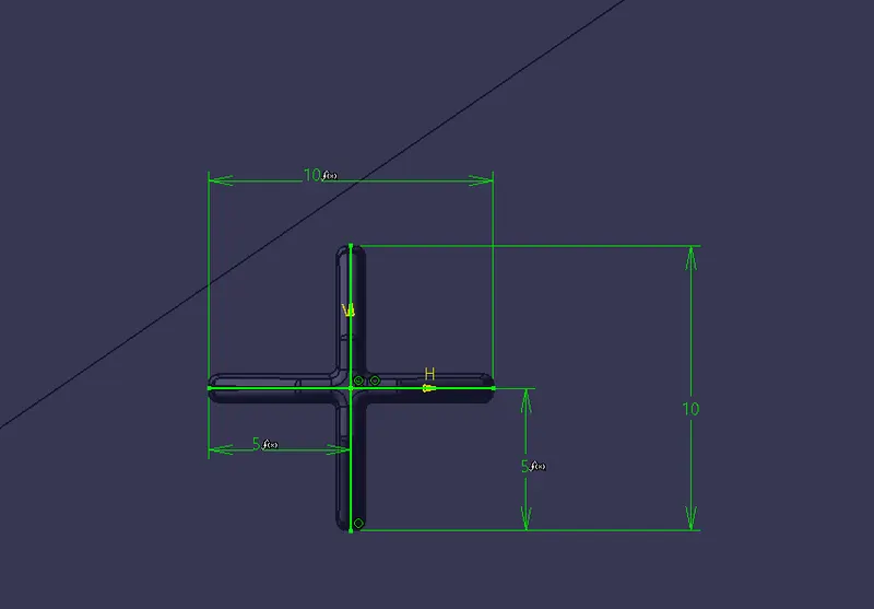
First, sketch a 4-way locator on the body. Once you have the sketch, add a 20mm height pad and thicken it to 1.3mm. Then, draft it at a 0.5-degree angle in the direction of the tooling axis. To finish, apply a 5mm chamfer with a 45-degree inclination and a fillet with a 0.20mm radius. After completing the first locator, use the translate feature to copy and paste it to create a second 4-way locator.
For Creating Heat Stakes :
To create a heat stake with supporting ribs, follow these steps:
- Start by creating a sketch on the surface where you want to create the heat stake.
- Draw the shape of the heat stake in the sketch.
- Pad the sketch to 18mm height and apply a draft angle of 0.5deg on both sides (inside and outside).
- Apply a fillet with a 0.20mm radius to the edges of the heat stake.
- Next, create the supporting ribs by drawing a sketch and padding it to a height less than that of the heat stake and 1mm in thickness.
- Apply a draft angle of 0.5deg in the tooling axis direction to the ribs.
- Apply a fillet with a 0.20mm radius to the edges of the ribs.
- Use the union trim command to remove the ribs that are inside the heat stake as per the requirement.
Make sure to review and modify the dimensions and features as necessary before finalizing the design.
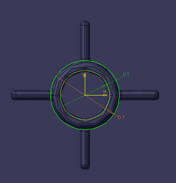
Now We Have Done Creating the Heat Stake we have to create other also So for creating the other heatstakes we have to
Copy the heatstake body and use paste special with link option to the main Part we have and the we can transpose the pasted heat stake to the required position using point to point transpose. and then We have to Insert a new body and assemble all the Heat stake body's we have created now we have only one parent for all the heat stakes we can use union trim to the body we want to keep and remove the other side.
after getting the final surface have to do a Draft analysis for the locators and heat stakes for an angle of 0.5 degree as we have given draft angle of 0.5mm.
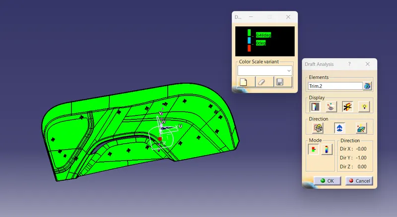
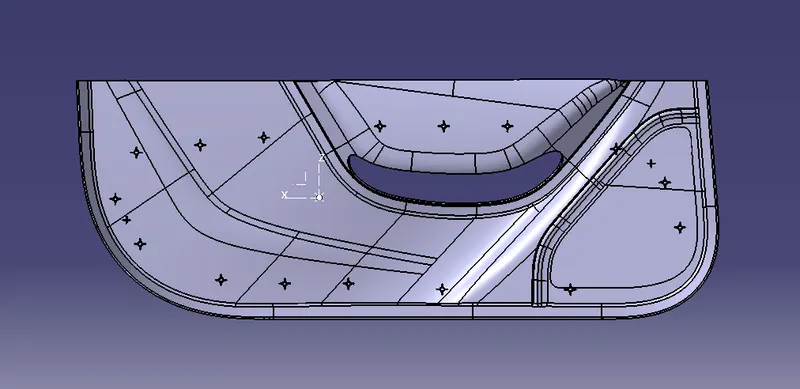
here we have done with the Final Part with Locators and heatstakes.
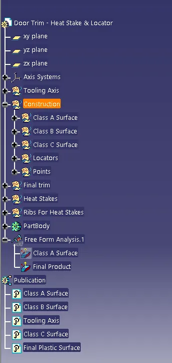
arrange the geometric set properly to keep confusions out of the part