Week 10 - Challenge 2- Attachment Feature Creation (Dog House)
WEEK 10 CHALLENGE 2 ATTACHMENT FEATURE CREATION (DOGHOUSE)
DOGHOUSE:
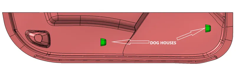
Doghouse is an engineering feature used in plastic component designing. these are support features of a plastic component. dog houses are subjected to drafting and will be placed on the b surface.
UTILITIES:
- helps to eliminate sink marks
- solves length issue by placing the screw boss on top of a doghouse
- when have to have a perpendicular screw boss to tooling axis
DESIGN RULES OF DOGHOUSE:
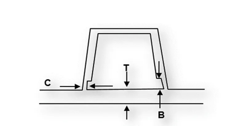
- doghouse wall thickness at intersection of part wall (C) should be 40% or less than main wall T
- height of B should be between 3 to 6 mm
- main doghouse width is 12 mm
- 2:1 ratio of width to height
- draft 1.5 degree
TOOLING AXIS CREATION:
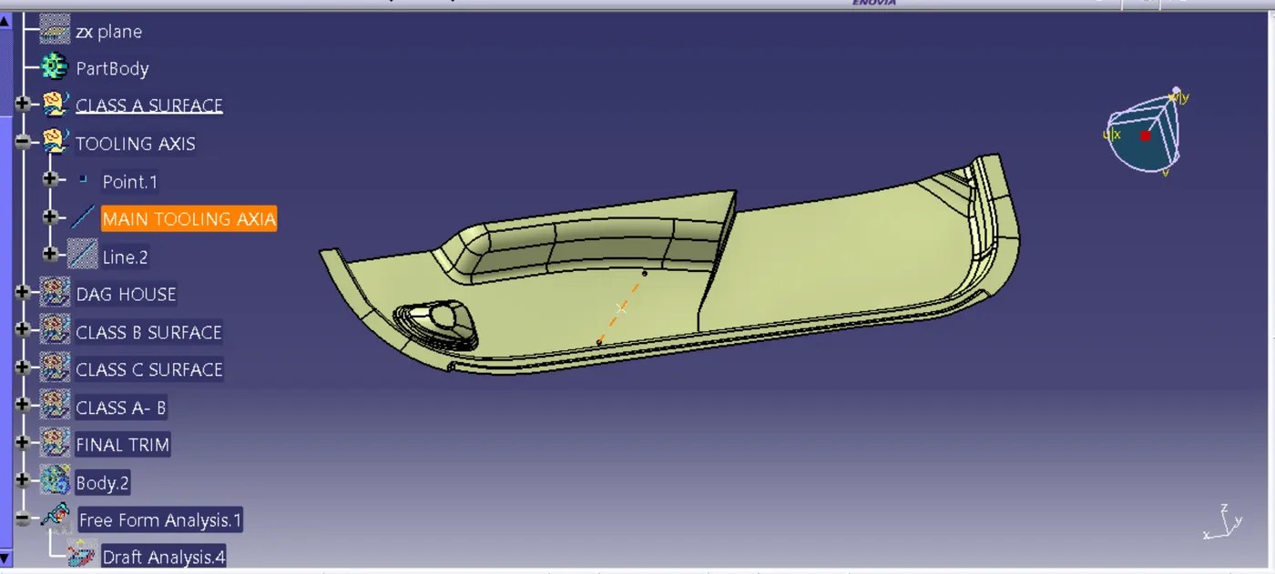
Tooling axis is the direction in which Mould travels. basically, there are two pieces for Mould, one cavity side and one possess projections of the component. the draft angle given for the component for ease of ejection, is drafted with reference to this tooling axis.
conducted visual inspection initially, then checked for, if there is any gaps or corrections by taking boundary of the component. Placing tooling axis perpendicular to the largest flat area of the component is more convenient for manufacturing. so, extracted largest face of the given class A and placed a point on middle of the surface. Created axis through this point perpendicular in direction.
DRAFT ANALYSIS ON CLASS A
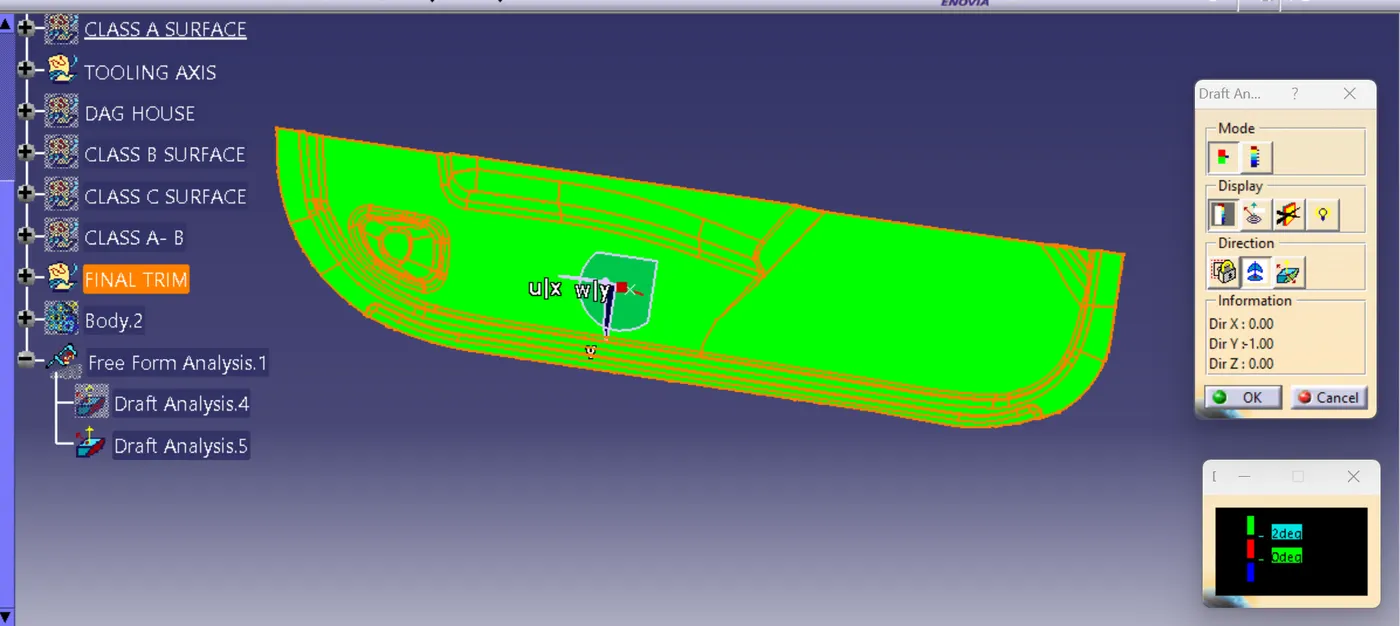
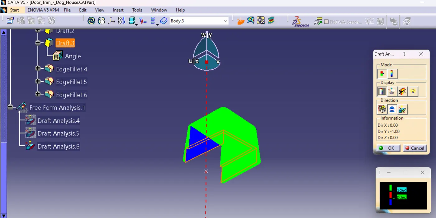
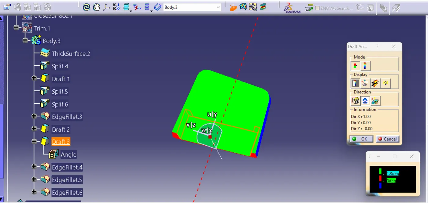
By performing draft analysis on the given class A surface enables to know whether the component is easily removable or not. this analysis is based on color ranges which indicates different colors for different angles.
- go to customize view parameter and select material mode in mesh
- select feature draft analysis from analysis option by going in insert option from tool bar
- place the compass align to tooling axis with the help of compass tool
- select the surface
- click display button on the window
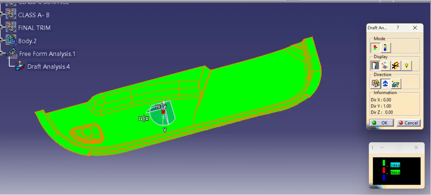
each color zones indicates each drafting angles, green indicates within given draft angle, red indicates zero and blue indicates negative angle
CREATION OF CLASS B SURFACE
start with creating separate geometrical set for class b, take an offset of the given class surface to a value of 2.5mm in inside direction. some patches would be there in the offsetted plane, most of the times, fillets are the cause of paths.
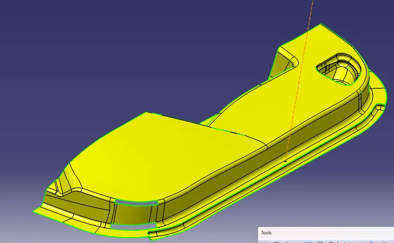
extract the surfaces on both sides of the patch and extrapolate them
then trim them together and give fillet.
do the same for each path and obtain desired surface b
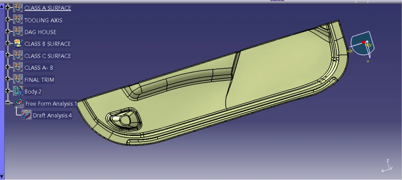
CLASS C CREATION:
- create boundaries at edges of class a
- select sweep with draft direction from sweep option.
- select the created boundary as guide curve and tooling axis as draft direction, with 3-degree angle projecting out from class a
- follow above sweep procedure for planes which are perpendicular to tooling axis
- for planes parallel to axis, sweep in 90-degree refence to the class a surface
- extrapolate the ends of swept planes and trim altogether to get the c surface
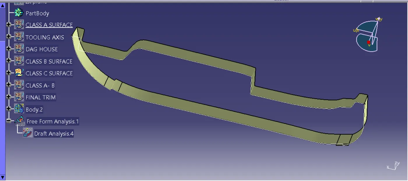
always try to give second limit in sweep to 2 mm, it helps to provide a proper join of the class a and c while trimming
trimmed class a and c
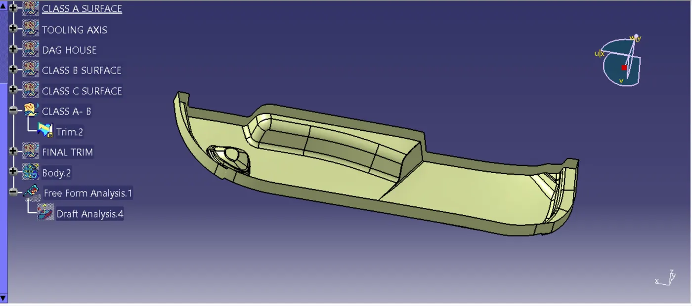
trimming A, B and C gives final component
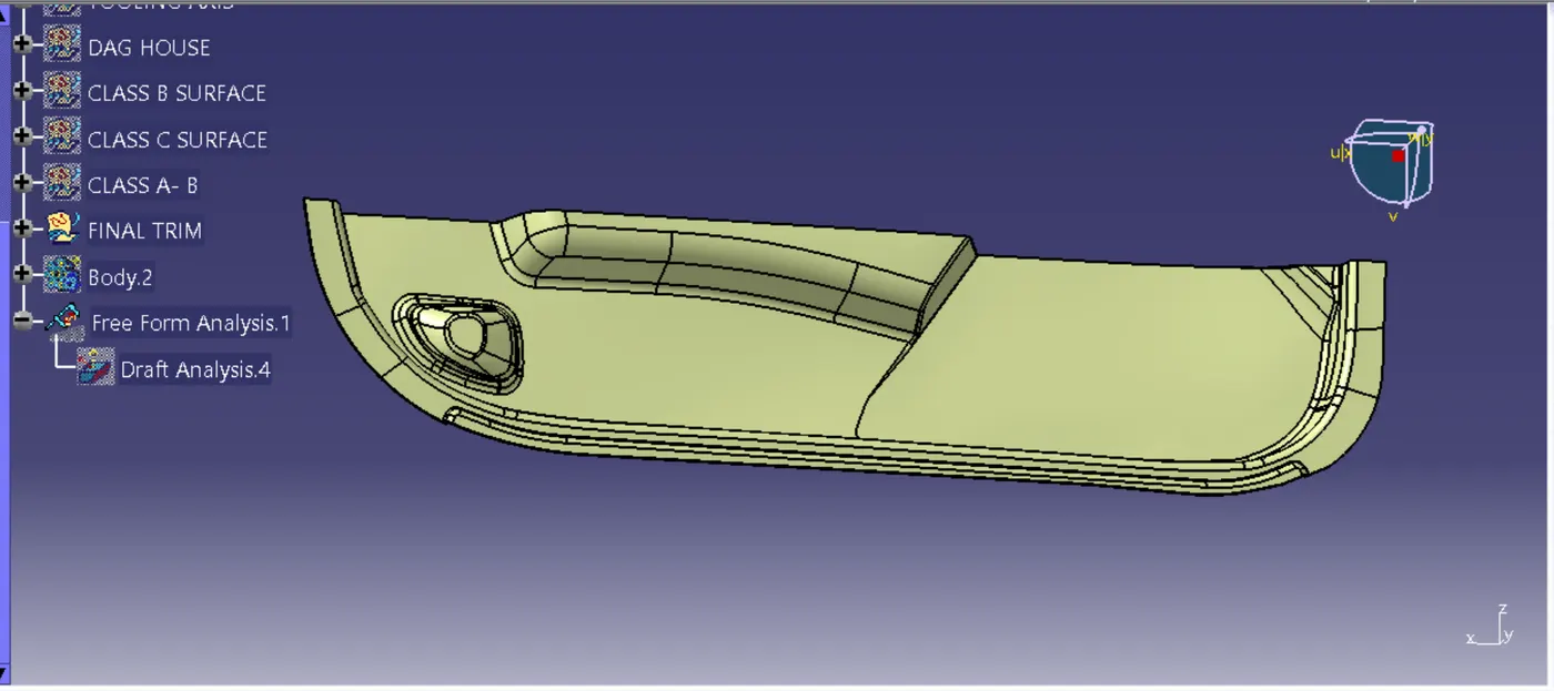
DRAFT ANALYSIS ON CLOSED BODY:
CONSTRUCTION OF DOGHOUSE
- created a point on the surface where doghouse is desired to place
- as the surface is not flat it cannot be taken as reference for the positioned sketch.so created an axis system on the point and took zx plane as reference for the sketch.
- created a 20*20 box in sketcher workbench and selected one side of the box as construction element.
- swept the box in 1.5 degree drafting to tooling axis.
- close the top of the extruded box creating a line on the edge and extruding it
- trim them together
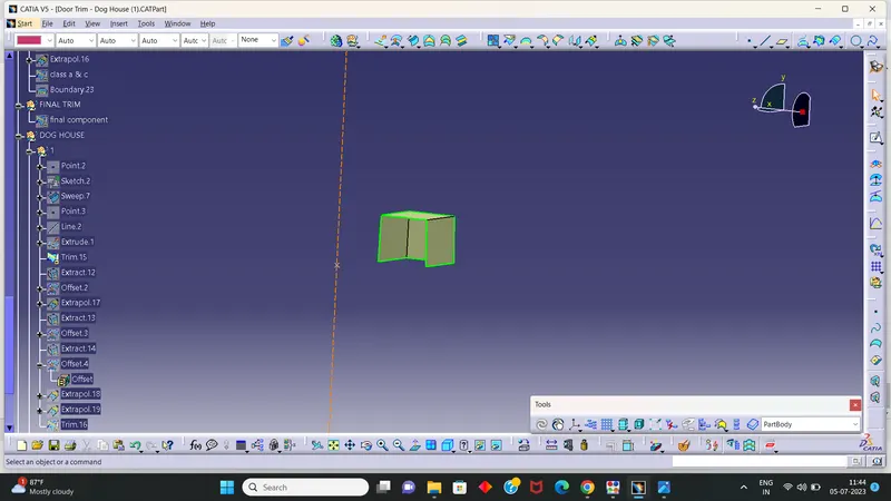
- go to part workbench, select thickening tool and thicken it inside.
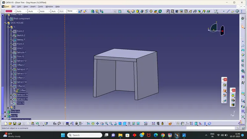
- create a side core axis in perpendicular direction to tooling axis
- give drafting of 1.5 degree for inner faces of the doghouse with respect to side core axis
- offset the inner faces of doghouse to outer and top of the house to inner to appropriate value
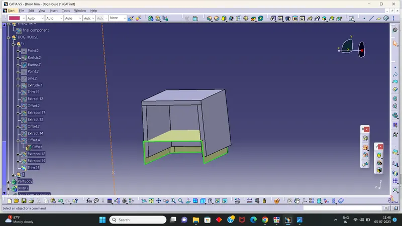
- trim them together
- split the solid doghouse with split tool in part workbench
- give drafting to the splatted horizontal faces
- fillet the edges
- add to part body
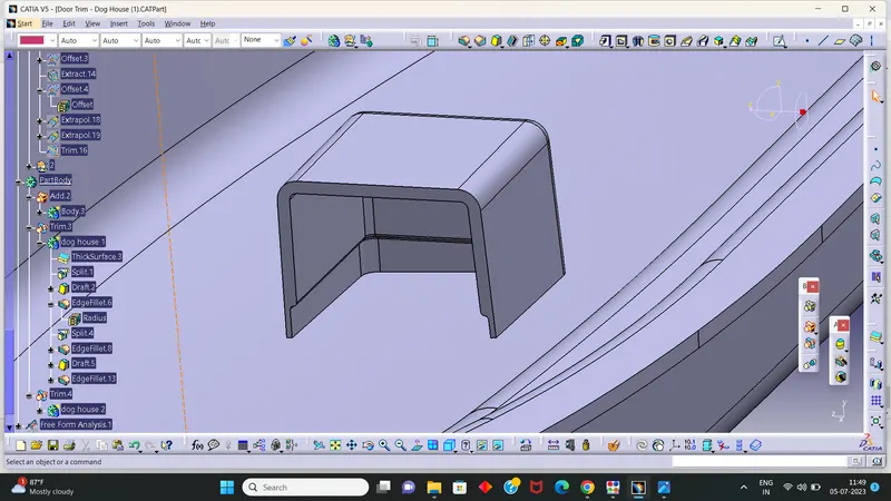
DRAFT ANALYSIS OF DOGHOUSE:
with tooling axis
with side core axis
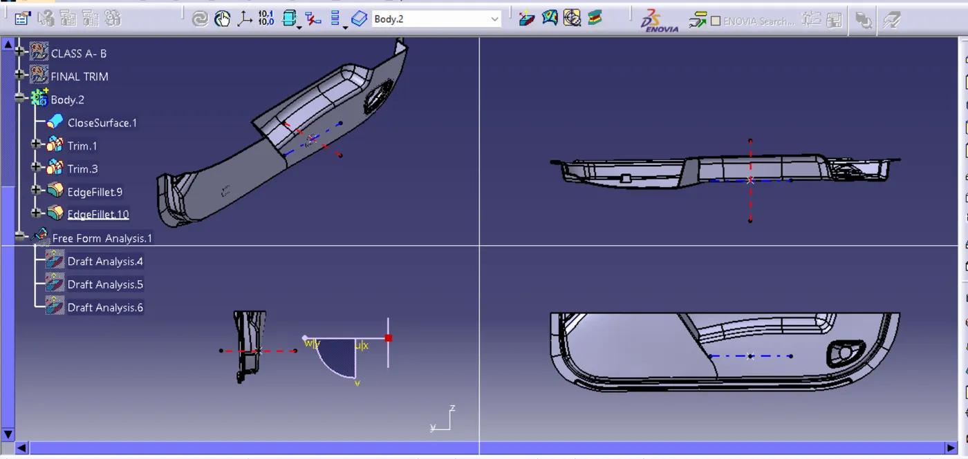
MULTI-VIWE:
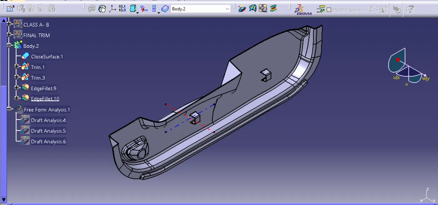
ISO-VIWE:
GIVEN CHALLENGE IMAGE: