Week 10 - Challenge 2- Attachment Feature Creation (Dog House)
AIM
To Create the Dog House for the Door Trim considering the design rules through the given Class-A surface.
Objective:
- Create the Tooling axis
- Design the class-B and class-C surfaces and join them.
- Use the Close Surface feature to make a solid body from the surface.
- Design the required dog house and analysis them.
- Perform the Draft analysis for the final component.
Design Methodology
Class-A surface means visible surface. It gives the aesthetic of the component which is created by the styling team and gives to the part design engineer to create the part with all engineering aspects.
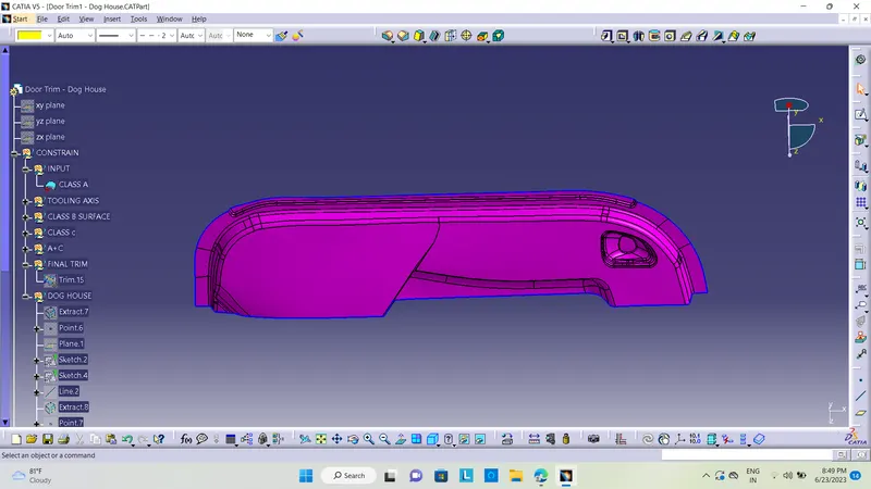
Given CLASS-A surface
Tooling Axis :
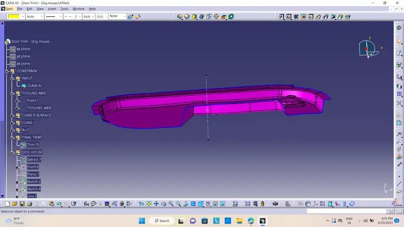
Class-A surface is first analyzed to create the tooling axis. where the molds pull apart in injection molding. Tooling direction is essential for plastic product design as it decides the direction for mold separation.
To create the tooling axis first we have to check the best suitable direction for tooling by using the compass. the y direction is suitable for creating the tooling axis because in the y direction most of the surfaces are clearing while performing draft analysis. Generally tooling axis is created using bisecting line method but here A line normal to the surface is created in the y direction and considered the tooling axis.
Y direction
DRAFT ANALYSIS OF A SURFACE:
- Draft analysis of the surface is carried to check if the surface or part can be manufactured with the required draft angle.
- Draft angle is needed for the component to clear the core and cavity surface as it would have shrunk towards the center while cooling.
- The draft angle in this design is 3 degrees. As A surface is a single surface there won't be much difference in color. The draft analysis of A-surface is shown below.
CLASS-B surface creation
Class-B surface means the thickness of a part it is not visible and is inside part. In other words, the Class-B surface is a surface below a certain thickness from the class-A surface. This is the surface that contains engineering aspects of a model.
- Crean ate offset surface of Cin LASS-A about 2.5mm inward direction.
- Check for discontinuity and rework on the offset surface using extract, multi-extract, multi sections surfaces.
- Join the surfaces and ensure the final CLASS-B surface created has no gaps.
CLASS-C surface creation
The surface that joins class-A and class-B surfaarethe s is class-C surface. Class C is often specified for interior surfaces not readily visible, surfaces that will be covered by another part when assembled
- Create the sweep concerningerence to the surface and tooling axismulti-extractingting the CLASS-A boundary
- Join the sweep surfaces by using commands like extrapolate, trmulti-sectiontion surface.
- Finally join all the sweep surfaces and ensure the continuity of the CLASS-C surface.
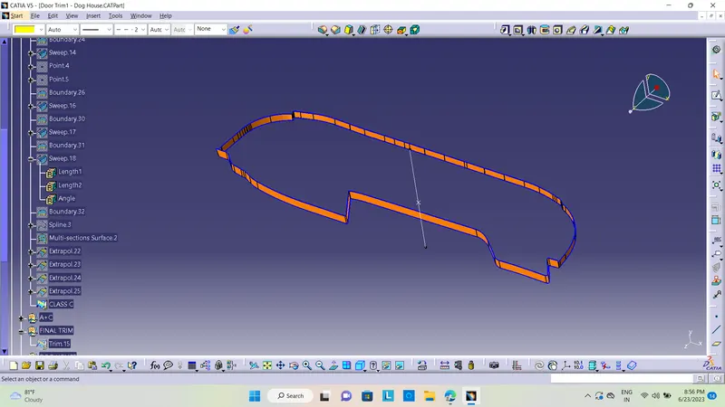
CLASS A AND CLASS C INTEGRATION:
Then trim the class-B surface to join (A+C) this will make sure that we get a closed surface. We can check it using the boundary tool, if it gives an error that means that the component is closed.
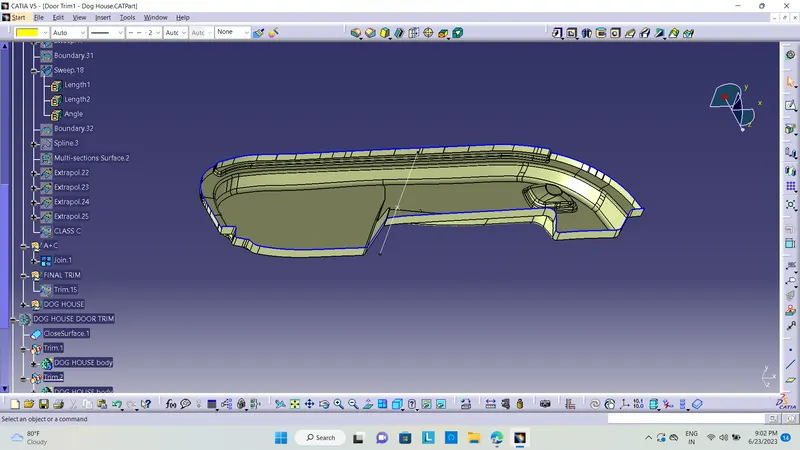
Creating the Final surface
- For creating the Finals door trim surface, join the CLASS-A and CLASS-C surfaces together.
- Then Extrapolate the B surfacea little bit outward direction to make sure that there would not be any gap when trimming with the joined surface.
- Then trim the extrapolated CLASS-B surface with Joined surface CLASS-A and CLASS C
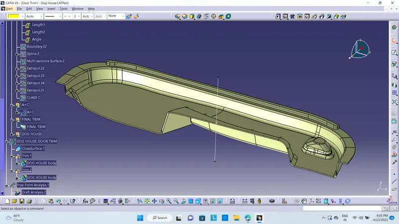
Then We go to the part design workbench and use to closed surface tool to create a solid body.
hence, we created our final Solid component.
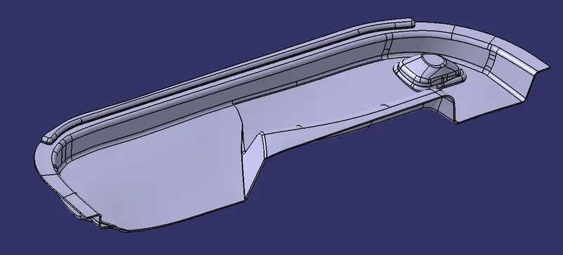
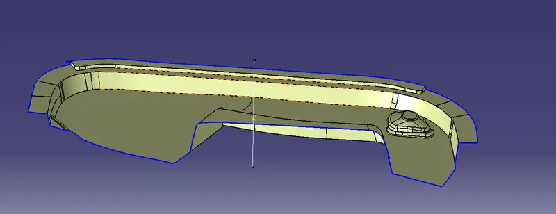
1. Dog House Design
- Attach a point on the surface of the solid door trim
- Select the plane normal to curve and the curve will be main tooling axis
- Use position sketch and draw the 3 side wall sketch by the line of the dog house 30x30
- Sweep the wall at 1.5 Deg with a height of approx. 23 mm
- Offset the plane 20 mm for making the dog house roof
- extrude the surface with the help of a line which is positioned on the offset plane
- Join all 4 faces (side wall and ceiling) and thicken them to 2.5 mm outward
- Use the draft of 1.5 deg for the outside of the dog house wall from part modelling with respect to the neutral surface and central tooling axis
- Use the draft of 0.5 deg for the inside of the dog house wall from part modelling with respect to the neutral surface and Side core tooling axis
- Apply the fillet of 1 mm inside of the dog house and outside fillet = wall thickness + inside fillet
- For making an undercuts-like structure extract the inside draft surface and offset 40% of the central wall thickness to the outward direction
- Offset the Base sketch extruded surface height of 3 - 6 mm
- Trim both above offset surface and thicken approx. 1.5 mm
- Use the Boolean operation and make the undercut of the dog house
- Now copy the dog house and paste it with the link to the destination place points
- Now you can transform the copy of the dog house into different positions.
- Use union trim and combine dog house and door trim.
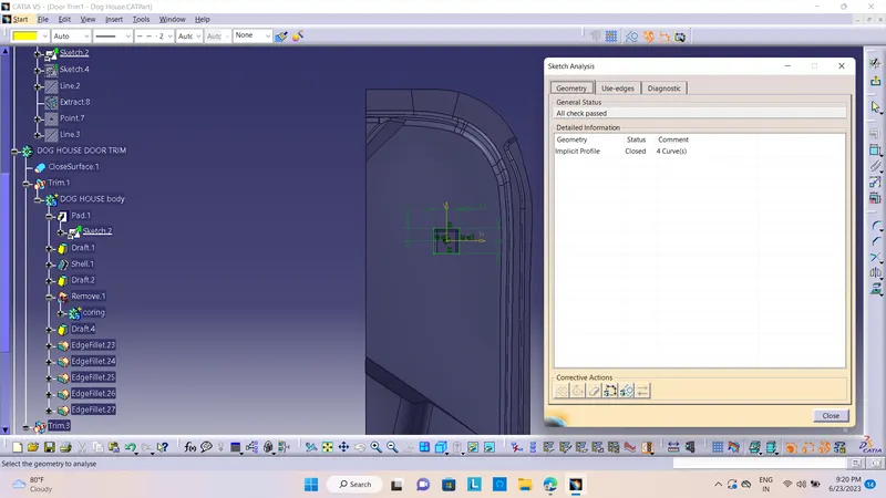
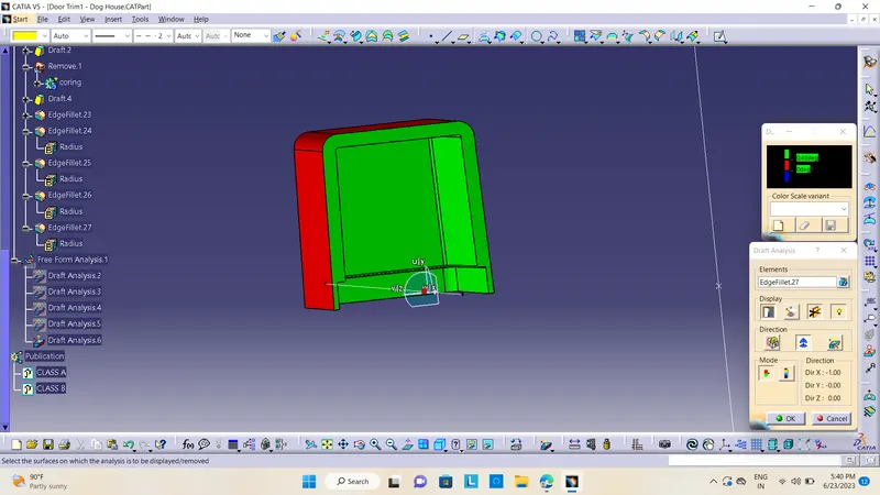

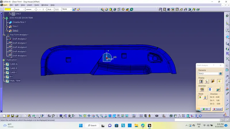
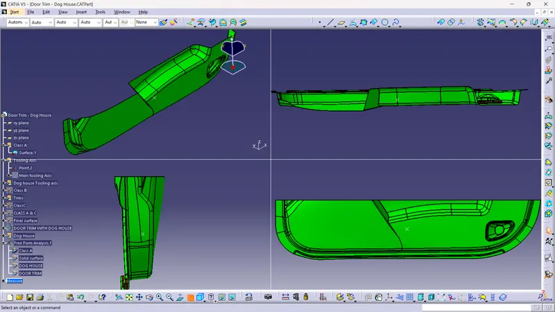
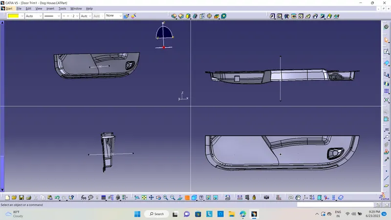
- Screenshots of the completed design in various orientations (Isometric, Front, Side, and Top View)
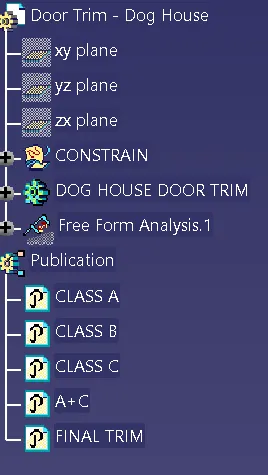
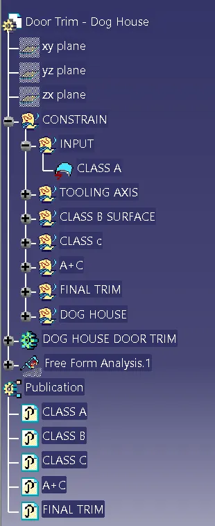
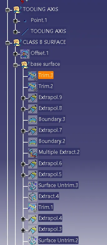
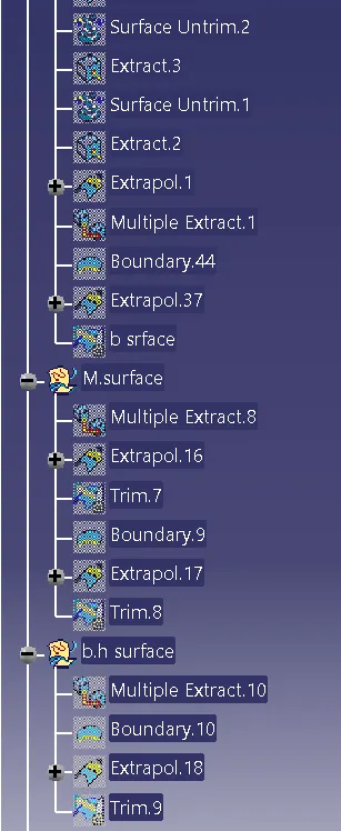
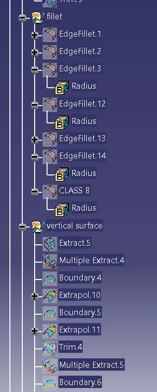
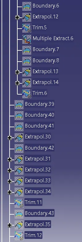
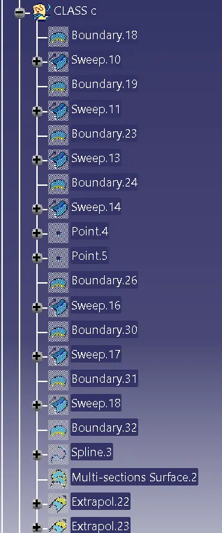
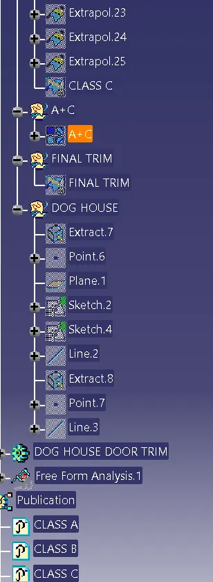
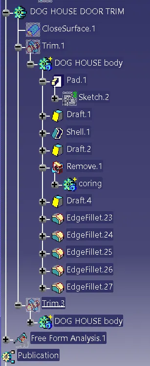
TREE STRATURE
Conclusion
Using the provided CLASS A surface of the door trim generated main and side core tooling axes, I was able to build CLASS B and C surfaces with success. performed a draft study on the dog house and the final component.