Week 10 - Challenge 2- Attachment Feature Creation (Dog House)
Draft Analysis of CLASS-A surface
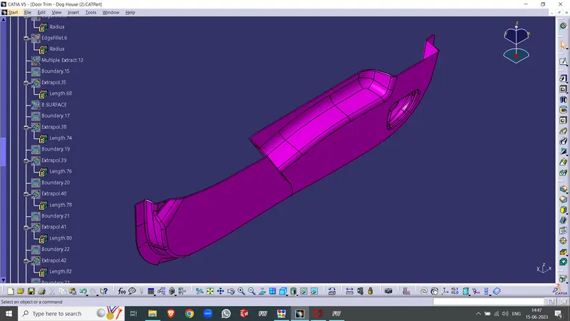
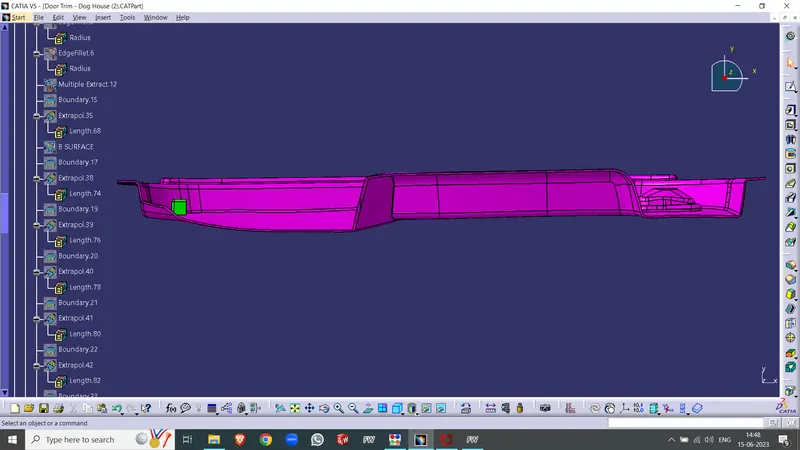
Completed Design in various orientations
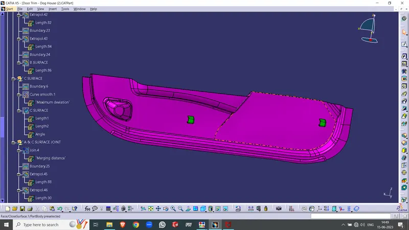
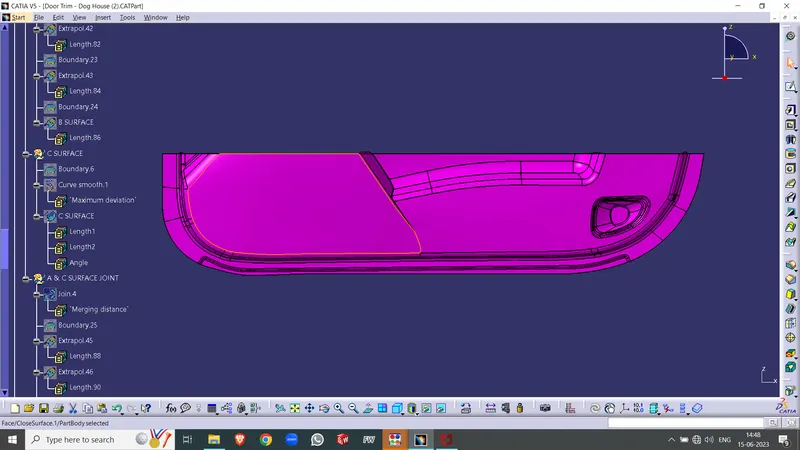
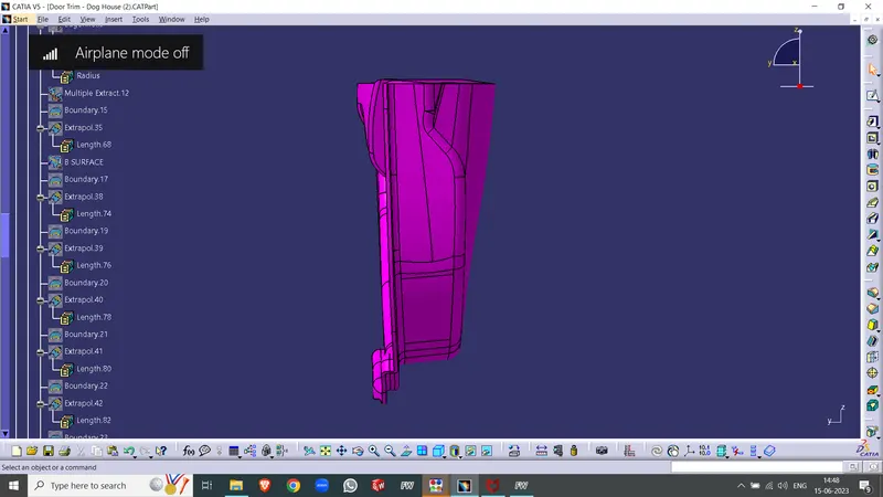
Draft Analysis
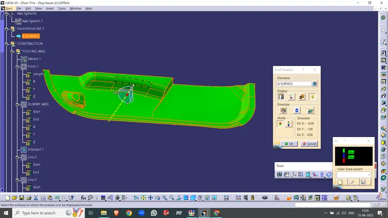
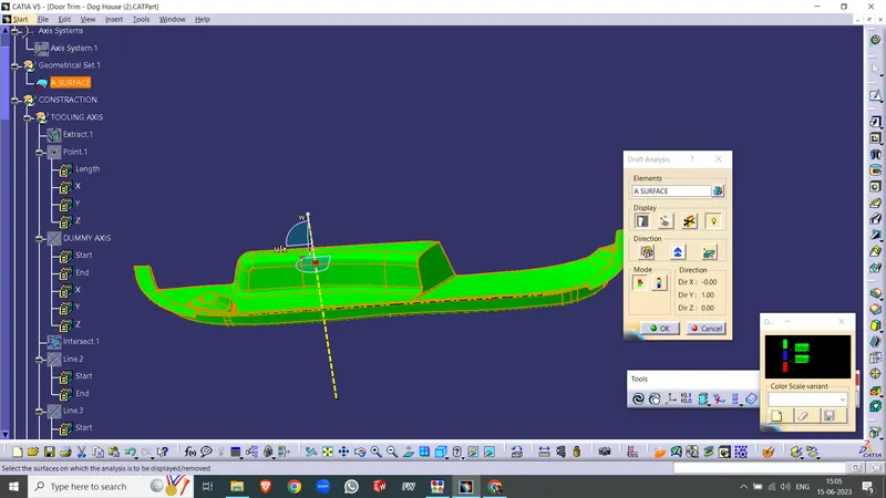
The Draft Analysis command allows you to assess the ease of removing a drafted part. This analysis is based on color ranges that identify areas on the analyzed element where deviations from the draft direction exceed specified values.
Draft analysis is conducted after determining the tooling axis and is used to verify if the minimum draft angle of 3 degrees is maintained.
Here is the procedure for performing draft analysis:
- Switch the view mode of the component to customized parameter mode and select the shading mode as materials.
- Access the featured draft analysis tool from the insert menu.
- Utilize the compass to define the current drafting direction by clicking and dragging it to align with the Tooling axis.
- Lock the draft direction and initiate the draft analysis by clicking on the component.
- The analysis results are represented through color ranges, indicating areas where deviations from the desired draft direction occur.
Creating Tooling Axis
To establish the tooling axis, follow these steps:
- Manually adjust the compass to explore the optimal tooling direction.
- Upon analysis, it is determined that setting the y-axis as the tooling direction will successfully clear most of the faces without encountering difficulties.
- Select any surface and generate a mid-point on it.
- Create a dummy axis by drawing a line from the midpoint along the y-axis direction.
- Perform a draft analysis to evaluate whether the selected axis successfully clears the draft requirements. If the analysis indicates otherwise, create a new tooling axis accordingly.