Week 10 - Challenge 2- Attachment Feature Creation (Dog House)
Objective : To create the Dog House for the Door Trim through the given Class-A surface. To begin with, the tooling axis for the given Class-A Surface should be created meeting the requirements of the draft angle and at the end perform the Draft analysis on the model.
Take the Thickness of the component to be 2.5mm mm.
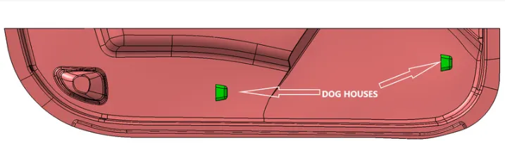
-
A-Surface
-
Thickness of component is 2.5mm
- Draft anglre is 1.5 degrees for outside & 0.5 for inside of dog house.
Procedure :
A ) Verifying Class A Surface :
The A-surface or the styling surface is first checked for any gaps and other issues in its surfaces. This Surface acts as the input surface so any correction to be done should be with approval from the styling team or done by them. A- perfect surface is the one when a boundary is created, the lines are only on the edges of a component and its holes or cutouts.
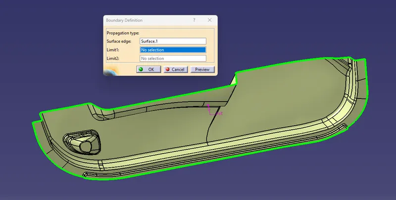
B ) Tooling Axis Creation :
Tooling axis is the direction in which a core or cavity of mold opens. This Axis is very important to determine the orientation of the component in mold, core and cavity design.
The tooling axis is created by the inertia method by using the steps as follow
-
Click “Measure inertia”
 and select the A-surface.
 -
Click “Create geometry” in the Measure Inertia window.
-
In the Creation of Geometry window, select Non-associative geometry.
-
Click “Center of Gravity”
-
The Inertia point is created.
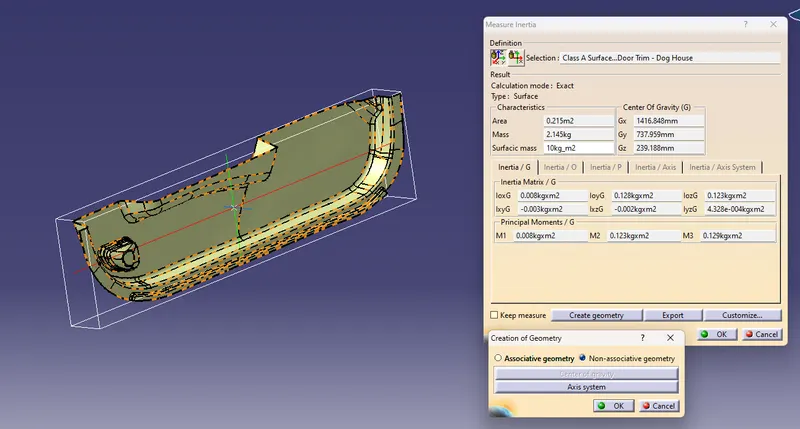
-
The component is viewed in all axes namely X,Y and Z.
-
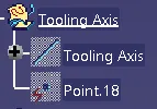
It is determined that the X-axis will be the direction for the Tooling axis and a line is created Using the CG point and X-direction as direction of the line.
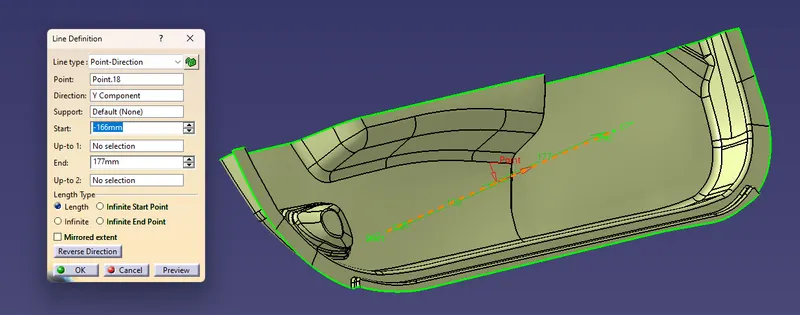
Tree Structure :
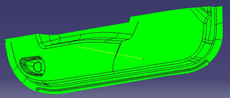
C ) Draft Analysis of Class A Surface :
Draft analysis of the surface is carried to check if the surface or part can be manufactured with the required draft angle.
Draft angle is needed for the component to clear the core and cavity surface as it would have shrunk towards the center while cooling.
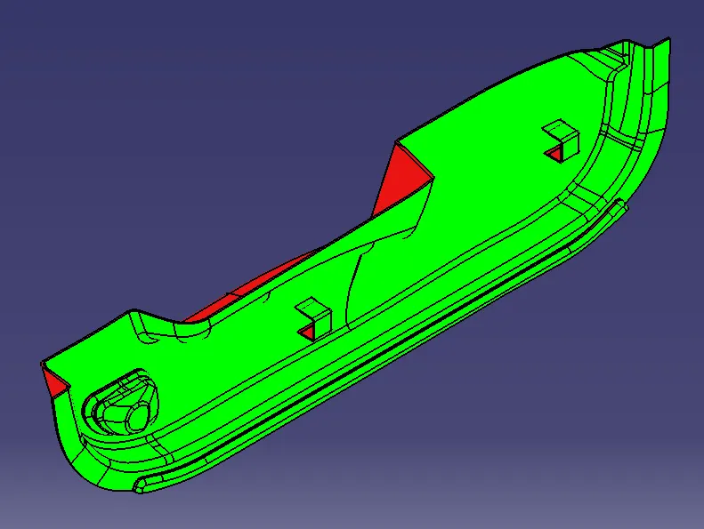
The draft angle in this design is 3 degrees. As A surface is a single surface there won't be much difference in color.
- After Tooling Axis Select the Feature Draft Analysis option from the Insert > Analysis > Feature Draft Analysis Option
 .
.
- Select the Class A Surface to analyze.
- Next click on Use the compass to define the new current draft direction option and make it align with the tooling axis by dragging it to the axis
 .
.
- Next use the lock option
 to lock the compass to the tooling Axis.
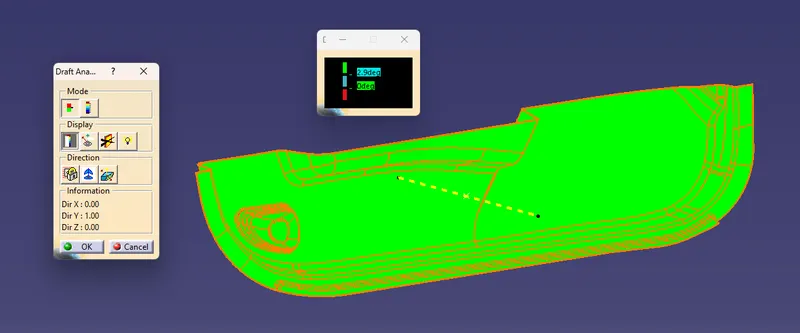
- If the color appears blue just click the invert option on the right side of the draft direction axis button
 .
.
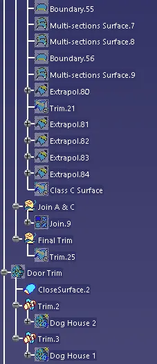
Tree Structure :

D ) Creating Class B Surface Creation :
- The A-surface is offsetted by 2.50mm as it is the thickness required.
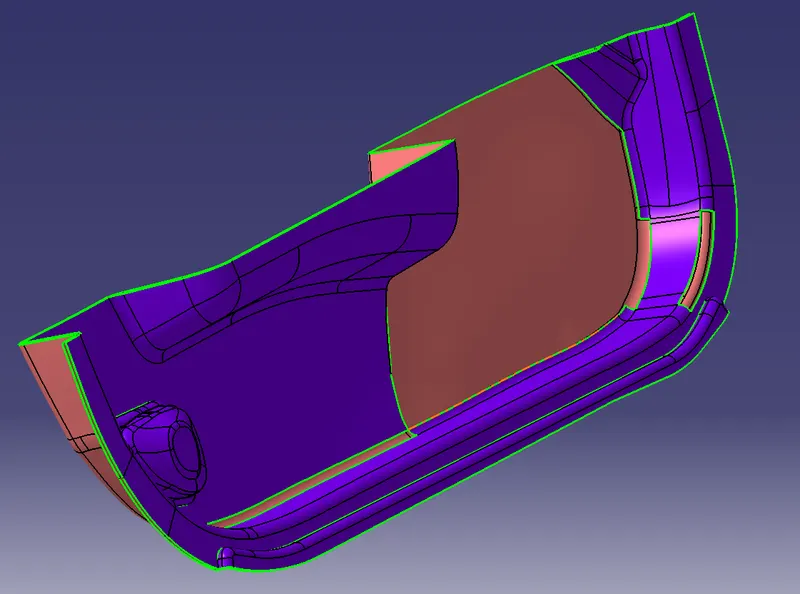
- As there are various fillets in the A surface therefore after offset they get removed.
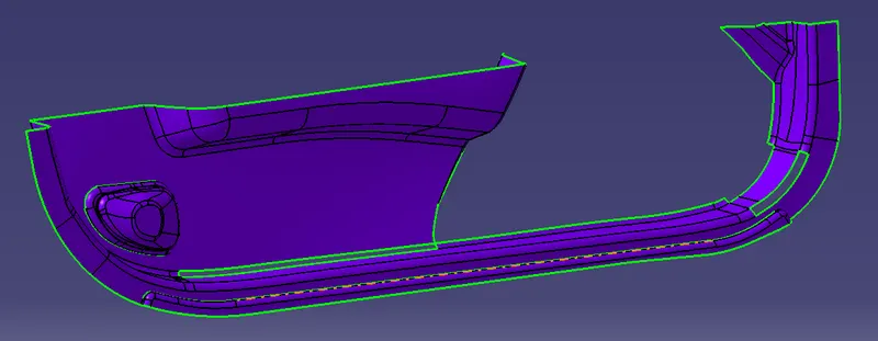
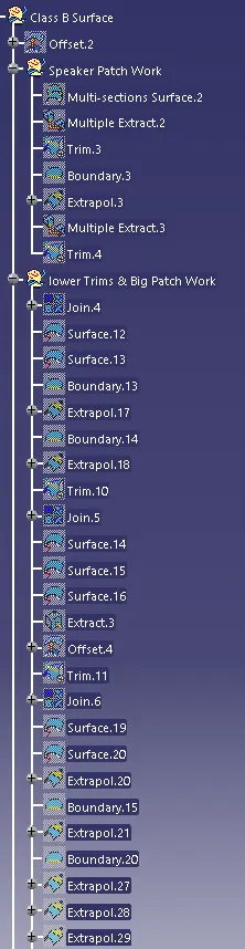
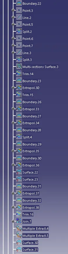
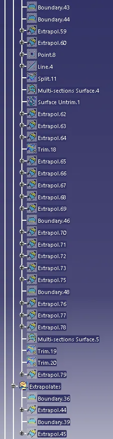
- To correct the surface we have to do patch work using the commands Extract, Multiple-Extract, Boundary, Extrapolate, Multi-sections, Trim.
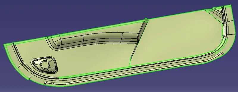
- Next Extrapolate the surface from all directions.
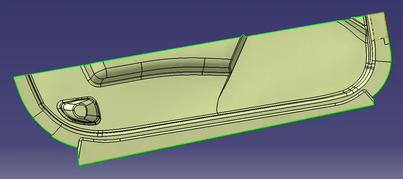
- This will be the final B Surface.
E ) Class C Surface Creation :
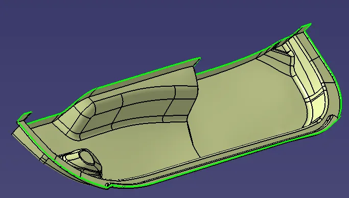
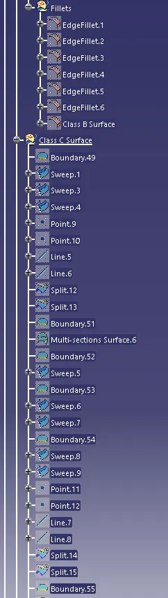
- Use the boundary command
 to get the edge of the class A.
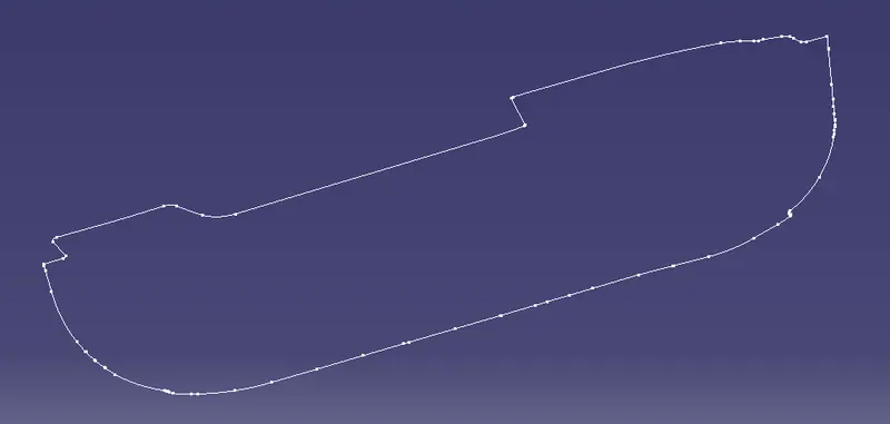
- use the sweep command
 and give the boundary, tooling axis and draft angle as input to get the Class C Surface.
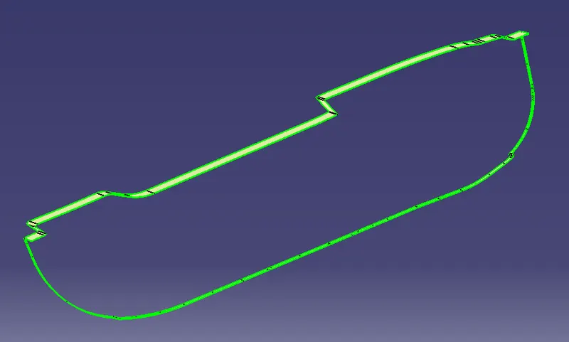
- Use the join command
 to join the class C & Class A Surfaces.
F ) Final Creation :
- Use the Joined Surface & Class B Surface and make a trim.
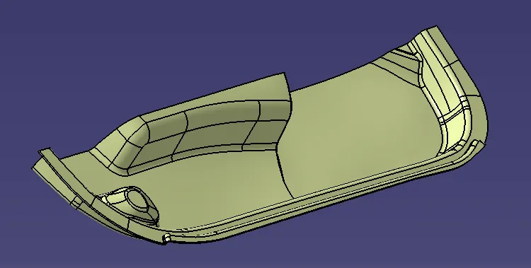
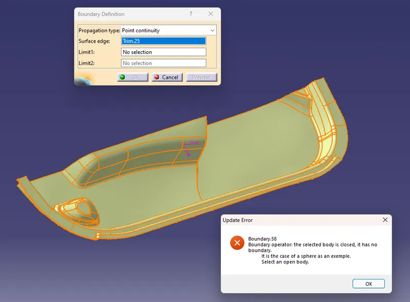
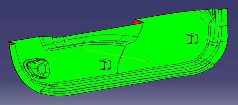
- All the surfaces (A,B,C) are joined together to form a closed body.Boundary is selected and the body is picked. Since an error popped up it can be understood that all surfaces are joined with each other to form a proper closed surface body.
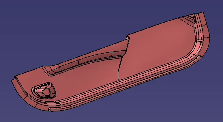
G ) Closed Surface :
- Go to Part > Body > Closed Surface command
 and we have a final solid part.
Tree Structure Class B & C Creation :
Draft Analysis For Class A Surface
Draft Analysis For Closed Surface
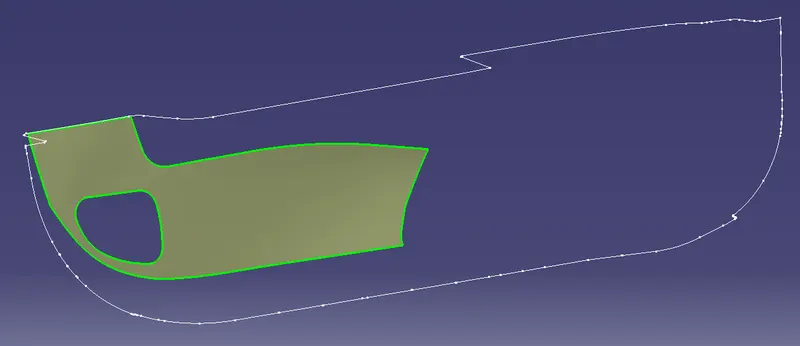
H ) Dog House Creation :
- Extract the base patch of the part where you want to create the Dog House using the Extract Command
 .
.
- Create a positioned Sketch for the dog house.
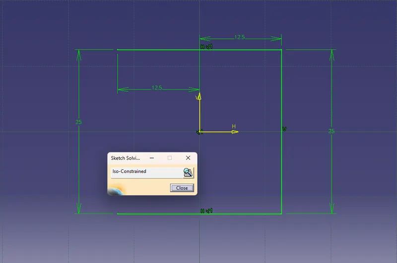
- Use the sweep command
 with the tooling axis with 1.5 degrees of draft.
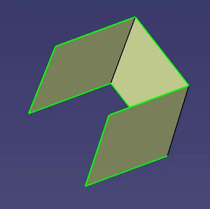
- using the Extrude, Extrapolate, trim command make a rough dog house.
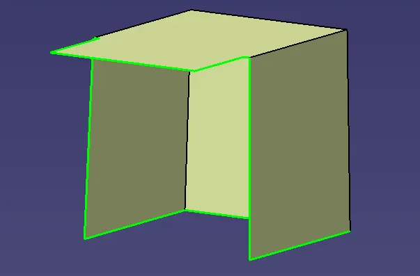
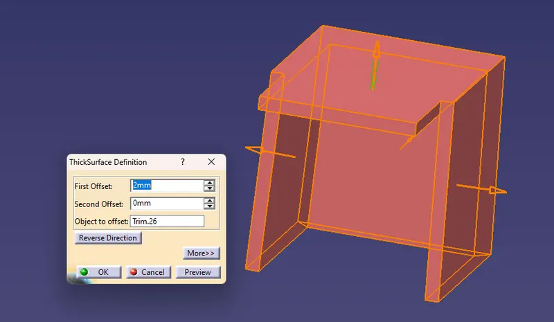
- Use thicken Command
 , to get the dog house thickness.
- For creating the contact area of dog house, we make offset of the body. Then offset the top portion down to get the required distance at contacting point.
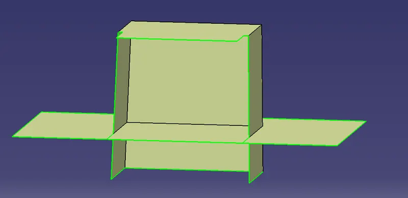
- Then trim to get the split body.
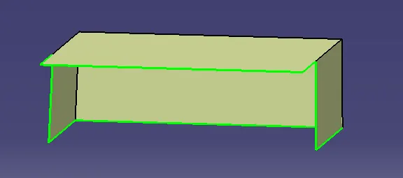
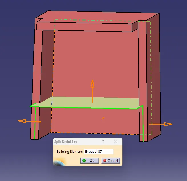
- Then use Split command
 then split the thicken and surface body.
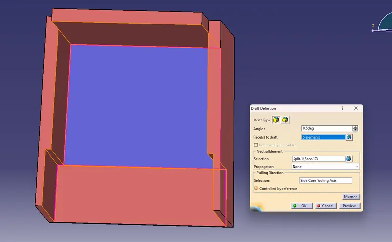
- Then give draft using the side core axis for inside of the dog house with 0.5 degrees.
- Then use a extrapolated extract of the back of dog house to split with the drafted body toget required shape.
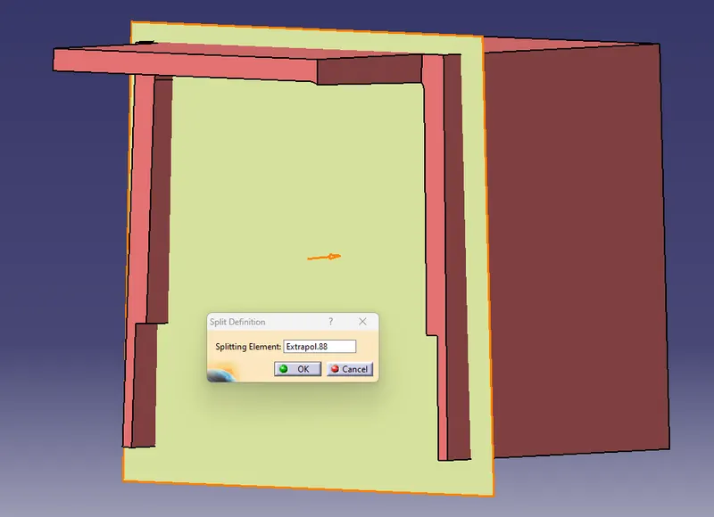
- Then give Fillet inside 1mm and outside 3mm.
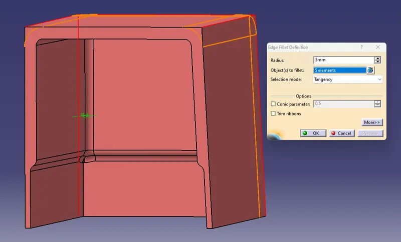
- Our Dog House is created.
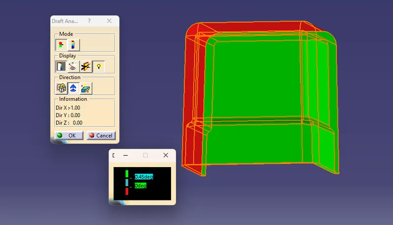
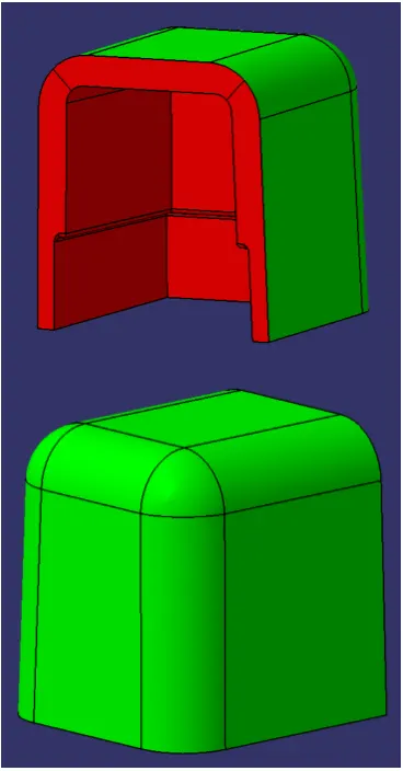
- Then copy the doghouse body and use paste special > As result with link.
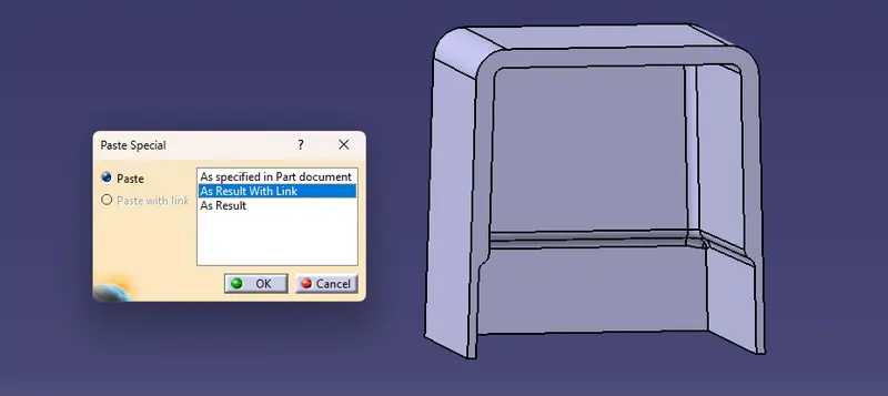
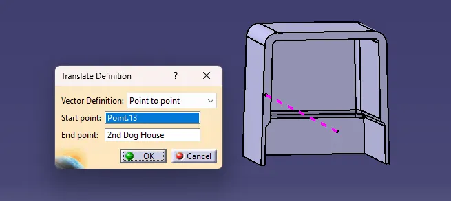
- We get a new dog house body. We translate this body to the required position, with point to point translate.
- Then use the boolean operation, Union Trim and make a body with the closed surface.
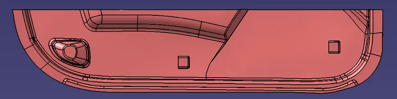
Our Lower Door Trim is created with Dog House.
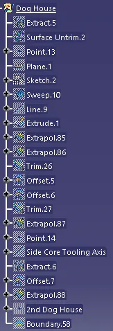
Tree Structure :
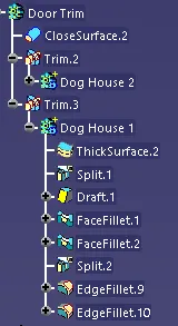
Views :
Front
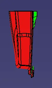
Side
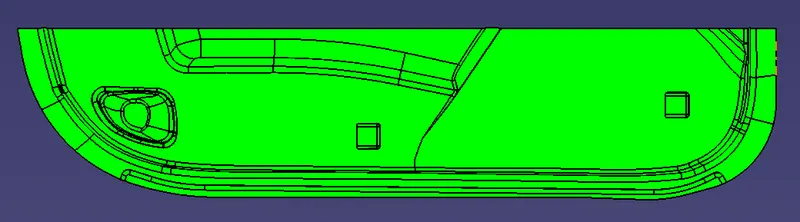
Top
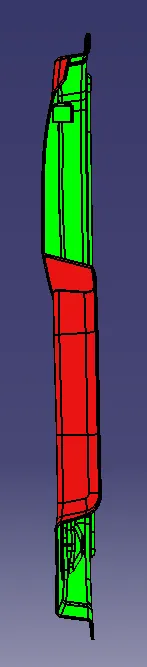
Isometric
Conclusion : Created the plastic component in Catia V5 using the given Class A Surface.
- Created the tooling axis.
- Ceated the Class B Surface.
- Created the Class C Surface.
- Created the Closed Surface from Surface geometry.
- Published the Class A, B & C Surface, Tooling Axis & Door Trim.
- Created the Dog House.
- Did the Draft Analysis.